1988 OPEL CALIBRA heater
[x] Cancel search: heaterPage 237 of 525
4Position a container beneath the tank, then
disconnect the bottom hose and allow the
contents of the tank to drain into the
container. Suspend the bottom hose as high
as possible above the engine to prevent
coolant loss.
Refitting
5Refitting is a reversal of removal, but on
completion check and if necessary top-up the
coolant level, as described in Section 4. The
coolant drained from the expansion tank
during removal can be re-used, provided it
has not been contaminated.
Coolant level sensor
6The coolant level sensor, where fitted, is an
integral part of the expansion tank cap. If the
level sensor is faulty, the complete cap
assembly must be renewed.
14Temperature gauge sender -
removal and refitting
2
Removal
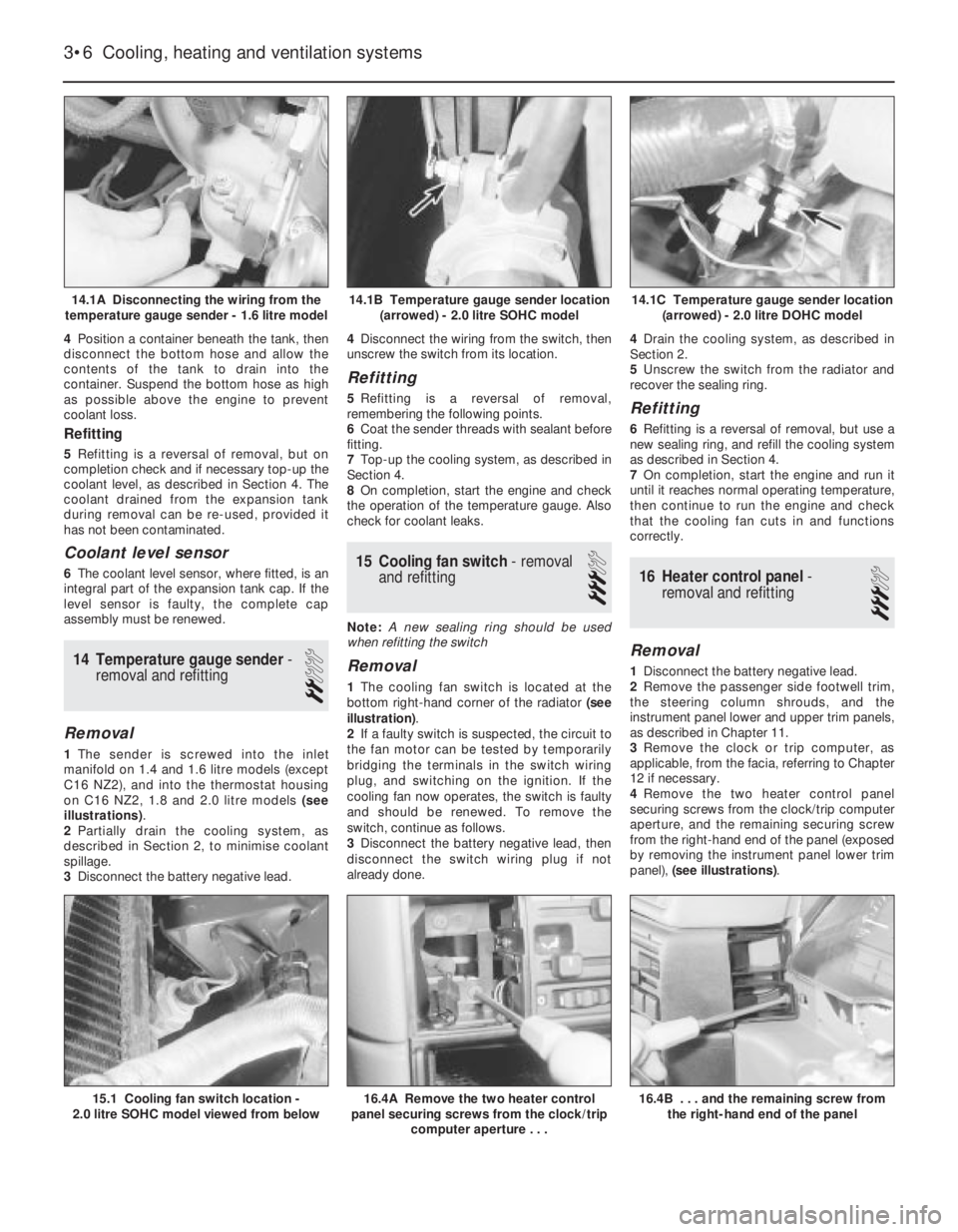
1The sender is screwed into the inlet
manifold on 1.4 and 1.6 litre models (except
C16 NZ2), and into the thermostat housing
on C16 NZ2, 1.8 and 2.0 litre models (see
illustrations).
2Partially drain the cooling system, as
described in Section 2, to minimise coolant
spillage.
3Disconnect the battery negative lead.4Disconnect the wiring from the switch, then
unscrew the switch from its location.
Refitting
5Refitting is a reversal of removal,
remembering the following points.
6Coat the sender threads with sealant before
fitting.
7Top-up the cooling system, as described in
Section 4.
8On completion, start the engine and check
the operation of the temperature gauge. Also
check for coolant leaks.
15Cooling fan switch -removal
and refitting
3
Note: A new sealing ring should be used
when refitting the switch
Removal
1The cooling fan switch is located at the
bottom right-hand corner of the radiator (see
illustration).
2If a faulty switch is suspected, the circuit to
the fan motor can be tested by temporarily
bridging the terminals in the switch wiring
plug, and switching on the ignition. If the
cooling fan now operates, the switch is faulty
and should be renewed. To remove the
switch, continue as follows.
3Disconnect the battery negative lead, then
disconnect the switch wiring plug if not
already done.4Drain the cooling system, as described in
Section 2.
5Unscrew the switch from the radiator and
recover the sealing ring.
Refitting
6Refitting is a reversal of removal, but use a
new sealing ring, and refill the cooling system
as described in Section 4.
7On completion, start the engine and run it
until it reaches normal operating temperature,
then continue to run the engine and check
that the cooling fan cuts in and functions
correctly.
16Heater control panel -
removal and refitting
3
Removal
1Disconnect the battery negative lead.
2Remove the passenger side footwell trim,
the steering column shrouds, and the
instrument panel lower and upper trim panels,
as described in Chapter 11.
3Remove the clock or trip computer, as
applicable, from the facia, referring to Chapter
12 if necessary.
4Remove the two heater control panel
securing screws from the clock/trip computer
aperture, and the remaining securing screw
from the right-hand end of the panel (exposed
by removing the instrument panel lower trim
panel), (see illustrations).
3•6Cooling, heating and ventilation systems
14.1A Disconnecting the wiring from the
temperature gauge sender - 1.6 litre model14.1C Temperature gauge sender location
(arrowed) - 2.0 litre DOHC model
16.4B . . . and the remaining screw from
the right-hand end of the panel16.4A Remove the two heater control
panel securing screws from the clock/trip
computer aperture . . .15.1 Cooling fan switch location -
2.0 litre SOHC model viewed from below
14.1B Temperature gauge sender location
(arrowed) - 2.0 litre SOHC model
Page 238 of 525
5Working through the passenger footwell,
reach up behind the facia, and disconnect the
bowden cables from the control levers at the
rear of the heater control panel. Note that
each cable is secured by a plastic clip, and in
some cases, by an additional metal clip,
which must be released before the cable end
can be disconnected from the control lever
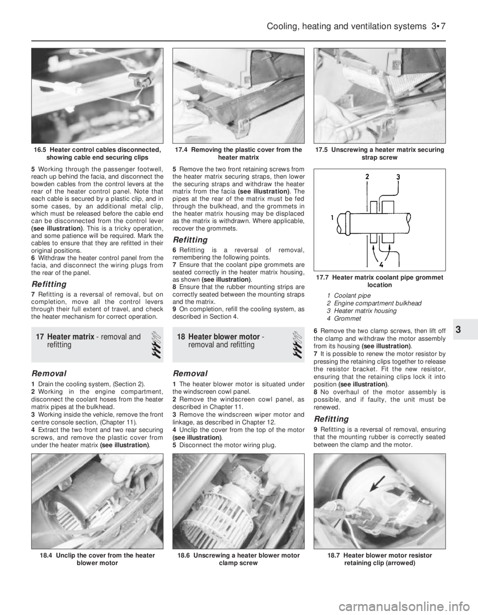
(see illustration). This is a tricky operation,
and some patience will be required. Mark the
cables to ensure that they are refitted in their
original positions.
6Withdraw the heater control panel from the
facia, and disconnect the wiring plugs from
the rear of the panel.
Refitting
7Refitting is a reversal of removal, but on
completion, move all the control levers
through their full extent of travel, and check
the heater mechanism for correct operation.
17Heater matrix -removal and
refitting
3
Removal
1Drain the cooling system, (Section 2).
2Working in the engine compartment,
disconnect the coolant hoses from the heater
matrix pipes at the bulkhead.
3Working inside the vehicle, remove the front
centre console section, (Chapter 11).
4Extract the two front and two rear securing
screws, and remove the plastic cover from
under the heater matrix (see illustration).5Remove the two front retaining screws from
the heater matrix securing straps, then lower
the securing straps and withdraw the heater
matrix from the facia (see illustration). The
pipes at the rear of the matrix must be fed
through the bulkhead, and the grommets in
the heater matrix housing may be displaced
as the matrix is withdrawn. Where applicable,
recover the grommets.
Refitting
6Refitting is a reversal of removal,
remembering the following points.
7Ensure that the coolant pipe grommets are
seated correctly in the heater matrix housing,
as shown (see illustration).
8Ensure that the rubber mounting strips are
correctly seated between the mounting straps
and the matrix.
9On completion, refill the cooling system, as
described in Section 4.
18Heater blower motor -
removal and refitting
3
Removal
1The heater blower motor is situated under
the windscreen cowl panel.
2Remove the windscreen cowl panel, as
described in Chapter 11.
3Remove the windscreen wiper motor and
linkage, as described in Chapter 12.
4Unclip the cover from the top of the motor
(see illustration).
5Disconnect the motor wiring plug.6Remove the two clamp screws, then lift off
the clamp and withdraw the motor assembly
from its housing (see illustration).
7It is possible to renew the motor resistor by
pressing the retaining clips together to release
the resistor bracket. Fit the new resistor,
ensuring that the retaining clips lock it into
position (see illustration).
8No overhaul of the motor assembly is
possible, and if faulty, the unit must be
renewed.
Refitting
9Refitting is a reversal of removal, ensuring
that the mounting rubber is correctly seated
between the clamp and the motor.
Cooling, heating and ventilation systems 3•7
17.5 Unscrewing a heater matrix securing
strap screw
18.6 Unscrewing a heater blower motor
clamp screw18.7 Heater blower motor resistor
retaining clip (arrowed)18.4 Unclip the cover from the heater
blower motor
17.7 Heater matrix coolant pipe grommet
location
1 Coolant pipe
2 Engine compartment bulkhead
3 Heater matrix housing
4 Grommet
17.4 Removing the plastic cover from the
heater matrix16.5 Heater control cables disconnected,
showing cable end securing clips
3
Page 254 of 525
Excessive fuel consumption
MAir filter element dirty or clogged (Chapter 1).
MChoke cable incorrectly adjusted, or choke sticking - carburettor
models (Chapter 4A).
MFuel injection system fault - fuel-injected models (Chapter 4B).
MIgnition timing incorrect/ignition system fault (Chapters 1 and 5).
MTyres under-inflated (Chapter 1).
Fuel leakage and/or fuel odour
MDamaged or corroded fuel tank, pipes or connections (Chapter 4A
or 4B).
MCarburettor float chamber flooding (float height incorrect) -
carburettor models (Chapter 4A).
Excessive noise or fumes from exhaust system
MLeaking exhaust system or manifold joints (Chapters 1 and 4C).
MLeaking, corroded or damaged silencers or pipe (Chapters 1 and 4C).
MBroken mountings causing body or suspension contact (Chapter 1).
Pedal travels to floor - no pressure or very little
resistance
MBroken clutch cable (Chapter 6).
MIncorrect clutch cable adjustment (Chapter 6).
MBroken clutch release bearing or fork (Chapter 6).
MBroken diaphragm spring in clutch pressure plate (Chapter 6).
Clutch fails to disengage (unable to select gears).
MIncorrect clutch cable adjustment (Chapter 6).
MClutch disc sticking on transmission input shaft splines (Chapter 6).
MClutch disc sticking to flywheel or pressure plate (Chapter 6).
MFaulty pressure plate assembly (Chapter 6).
MClutch release mechanism worn or incorrectly assembled (Chapter 6).
Clutch slips (engine speed increases, with no
increase in vehicle speed).
MIncorrect clutch cable adjustment (Chapter 6).
MClutch disc linings excessively worn (Chapter 6).MClutch disc linings contaminated with oil or grease (Chapter 6).
MFaulty pressure plate or weak diaphragm spring (Chapter 6).
Judder as clutch is engaged
MClutch disc linings contaminated with oil or grease (Chapter 6).
MClutch disc linings excessively worn (Chapter 6).
MClutch cable sticking or frayed (Chapter 6).
MFaulty or distorted pressure plate or diaphragm spring (Chapter 6).
MWorn or loose engine or transmission mountings (Chapter 2A or 2B).
MClutch disc hub or transmission input shaft splines worn (Chapter 6).
Noise when depressing or releasing clutch pedal
MWorn clutch release bearing (Chapter 6).
MWorn or dry clutch pedal bushes (Chapter 6).
MFaulty pressure plate assembly (Chapter 6).
MPressure plate diaphragm spring broken (Chapter 6).
MBroken clutch disc cushioning springs (Chapter 6).
Fault Finding REF•15
REF
Overheating
MInsufficient coolant in system (Chapter 1).
MThermostat faulty (Chapter 3).
MRadiator core blocked, or grille restricted (Chapter 3).
MElectric cooling fan or thermoswitch faulty (Chapter 3).
MPressure cap faulty (Chapter 3).
MIgnition timing incorrect/ignition system fault (Chapters 1 and 5).
MInaccurate temperature gauge sender unit (Chapter 3).
MAirlock in cooling system (Chapter 1).
Overcooling
MThermostat faulty (Chapter 3).
MInaccurate temperature gauge sender unit (Chapter 3).
External coolant leakage
MDeteriorated or damaged hoses or hose clips (Chapter 1).
MRadiator core or heater matrix leaking (Chapter 3).
MPressure cap faulty (Chapter 3).
MWater pump seal leaking (Chapter 3).
MBoiling due to overheating (Chapter 3).
MCore plug leaking (Chapter 2A).
Internal coolant leakage
MLeaking cylinder head gasket (Chapter 2A or 2B).
MCracked cylinder head or cylinder bore (Chapter 2A or 2B).
Corrosion
MInfrequent draining and flushing (Chapter 1).
MIncorrect coolant mixture or inappropriate coolant type (Chapter 1).
Cooling system
Clutch
Fuel and exhaust systems
Page 264 of 525
AABS components- 9•2, 9•16
Accelerator cable- 4A•5, 4B•9
Accelerator pedal- 4A•5
Acknowledgements- 0•4
Aerial- 12•17
Air cleaner- 1•3, 1•13, 4A•3, 4B•4
Air box- 4B•5
Air pump/cut off valve- 4C•2
Air temp control- 4B•5
Air vents- 3•8
Airbag- 12•19
Airflow meters- 4B•12
Alternator- 5•5
Alternator V-belt check- 1•12
Anti theft alarm- 12•19
Anti-roll bars- 10•8, 10•13, 10•17
Antifreeze mixture- 0•12, 0•17, 1•2, 3•3
ATF- 0•17, 1•2, 1•11, 7B•3
Automatic choke unit- 4A•9
Automatic transmission- 7B•1 et seq
cooler pipes and hoses - 7B•5
ECU - 7B•5
fault diagnosis - REF•12, REF•16
fluid - 0•17, 1•2, 1•11, 7B•3
kickdown switch - 7B•3
removal and refitting - 7B•6
selector control cable - 7B•4
speed sensors - 7B•6
starter inhibitor switch - 7B•3
temperature sensor - 7B•5
BBattery- 0•6, 0•15, 5•5
Bearings (engine)- 2A•31
Bleeding the brakes- 9•3
Bleeding the power steering- 10•22
Blower motor- 3•7
Body damage- 11•2
Body electrical systems - 12•1 et seq
Bodywork and fittings- 11•1 et seq
Bonnet- 11•4
Bonnet lock/release cable- 11•4
Boot lid- 11•4
Boot lid lock- 11•5
Bores- 2A•33
Brake checks- 1•12,
Braking system- 9•1 et seq
ABS components - 9•2, 9•16
backplate - 9•12
bleeding the brakes - 9•3
brake caliper - 9•8
brake disc - 9•10
brake drum - 9•11
brake fluid pipes and hoses - 9•18
brake lamp switch - 12•5
brake pads - 9•4
brake pedal - 9•21
brake shoes - 9•6
disc shield - 9•13
fault diagnosis - REF•12, REF•17
fluid - 0•13, 0•17handbrake adjustment - 9•18
handbrake cables - 9•19
handbrake lever - 9•20
master cylinder - 9•13
pressure valves - 9•18
vacuum servo unit - 9•15
wheel cylinder - 9•11
Bulbs- 12•2, 12•7, 12•11
Bumpers- 11•11
CCables:
bonnet release - 11•4
clutch - 6•2
handbrake - 9•19
selector automatic transmission - 7B•4
speedometer - 12•18
throttle - 4A•5, 4B•9
Caliper (brake)- 9•8
Camber- 10•1, 10•24
Camshaft- 2A•19, 2B•6
Camshaft housing- 2A•18
Camshaft oil seals- 2A•18
Capacities- 1•2
Carbon canister- 4C•4
Carburettor- 4A•5, 4A•11
Carpets- 11•2
Castor- 10•1, 10•24
Catalytic converter- 4C•3
Central door locking- 12•16
Centre console- 11•18
Cigarette lighter- 12•5
Clock- 12•6
Clutch- 6•1 et seq
cable - 6•2
fault diagnosis - REF•12, REF•15
pedal - 6•3
release bearing - 6•6
removal, inspection and refitting - 6•3
Coil- 5•9
Coil spring (rear)- 10•12, 10•15
Compression test- 2A•8
Computer components- 12•7
Connecting rods- 2A•29
Contents- 0•2
Control units- 4B•16, 7B•5
Conversion factors- REF•2
Coolant- 0•12, 0•17, 1•2, 3•3
Cooling, heating and ventilation systems-
3•1 et seq
blower motor - 3•7
coolant level sensor - 3•5
coolant pump - 3•4
cooling fan - 3•5
draining - 3•2
expansion tank - 3•5
fan switch - 3•6
fault diagnosis - REF•12, REF•15
filling - 3•2
flushing - 3•2
heater control panel - 3•6
heater matrix - 3•7
radiator - 3•3temperature gauge sender - 3•6
thermostat - 3•4
vents - 3•8
Courtesy lamp switch- 12•5
Crankcase ventilation system- 2A•7
Crankshaft- 2A•31
Crankshaft oil seals- 2A•26, 2B•6, 2B•9
Cylinder bores- 2A•33
Cylinder head- 2A•19, 2A•22, 2B•7DDents- 11•2
Depressurising fuel system- 4B•5
Differential bearing oil seal- 7A•3
Dimensions and weights- REF•1
Disc (brake)- 9•10
Distributor- 5•10
Door- 11•6
handle - 11•7
inner trim panel - 11•6
lock key battery - 1•13
mirror - 11•11
Driveshafts- 8•1 et seq
fault diagnosis - REF•12, REF•16
gaiter - 8•4
joint renewal - 8•4
Drum (brake)- 9•11
EEarth fault finding- 12•2
ECU’s - 4B•16, 7B•5
EGR components- 4C•2
Electric windows- 12•15
Electrical fault finding- 12•2
Electrical system (body)- 12•1 et seq
Electrical system- 0•14, 5•2
Electrical system fault diagnosis- REF•12,
REF•18
Electronic control units- 4B•16, 7B•5
Engine:
bearings - 2A•31
camshaft - 2A•19, 2B•6
camshaft housing - 2A•18
camshaft oil seals - 2A•18, 2B•6
codes - 2A•1, 2B•1
compartment - 0•10, 1•5
compression test - 2A•8
connecting rods - 2A•29
crankcase ventilation - 2A•7
crankshaft - 2A•31
crankshaft oil seals - 2A•26, 2B•6, 2B•9
cylinder bores - 2A•33
cylinder head - 2A•19, 2A•22, 2B•7
dismantling - 2A•12
DOHC - 2B•1 et seq
electrical systems - 5•1 et seq
fault diagnosis - REF•12, REF•13
flexplate (automatic transmission) - 2A•26
flywheel - 2A•26
main and big-end bearings - 2A•31
mountings (engine/transmission) - 2A•12,
2B•3
Index REF•25
REF
Note:References throughout this index are in the form - “Chapter number” • “page number”
Page 265 of 525
oil and filter renewal - 0•17, 1•2, 1•9
oil cooler - 2B•10
oil level - 0•12
oil pump - 2A•28, 2B•9
piston rings - 2A•30
piston/connecting rod - 2A•29
removal - 2A•8, 2B•3
SOHC - 2A•1 et seq
sump - 2A•27, 2B•9
timing belt - 2A•13, 2B•3, 2B•6
undershield - 11•13
valve lifters - 2A•24, 2B•9
valves - 2A•5, 2B•2
Environmental considerations- REF•4
Exhaust manifold- 4C•5
Exhaust system check- 1•11, 4C•5
Expansion tank- 3•5
FFan (radiator)- 3•5
Fault diagnosis- REF•12 et seq
automatic transmission - REF•12, REF•16
braking system - REF•12, REF•17
clutch - REF•12, REF•15
cooling system - REF•12, REF•15
driveshafts - REF•12, REF•16
electrical system - REF•12, REF•18
engine - REF•12, REF•13
fuel and exhaust systems - REF•12, REF•15
manual transmission - REF•12, REF•16
steering - REF•12, REF•17
suspension - REF•12, REF•17
Flexplate (automatic transmission)- 2A•26
Flushing (cooling system)- 3•2
Flywheel- 2A•26
Foglamp- 12•11
Fuel and exhaust (carburettor) systems-
4A•1 et seq
Fuel and exhaust (fuel injection) systems-
4B•1 et seq
Fuel and exhaust systems - emissions-
4C•1 et seq
Fuel and exhaust systems:
accelerator cable - 4A•5
accelerator pedal - 4A•5
air box - 4B•5
air cleaner - 1•3, 1•13, 4A•3, 4B•4
air pump/cut off valve - 4C•2
air temperature control - 4B•5
airflow meters - 4B•12
automatic choke - 4A•9
carbon canister - 4C•4
carburettor - 4A•5, 4A•11
catalytic converter - 4C•3
control unit - 4B•16
depressurising fuel system - 4B•5
EGR components - 4C•2
exhaust manifold - 4C•5
exhaust system check - 1•11, 4C•5
fault diagnosis - REF•12, REF•15
filler cap - 11•13
fuel filters - 1•3, 1•14, 4B•6
fuel flow damper - 4B•8
fuel injector(s) - 4B•13
fuel level sender unit - 4A•4, 4B•8
fuel pressure regulator - 4B•10
fuel pump - 4A•3, 4B•6fuel tank - 4A•4, 4B•7
fuel vapour separator - 4A•4
idle speed/mixture adjustment - 4A•7,
4A•12, 4B•9, 4B•11
inlet manifold - 4A•12, 4B•17
knock sensor - 4B•17
lambda sensor - 4C•4
manifolds - 4A•12, 4B•17, 4C•5
mixture (CO) - 4A•7, 4A•12, 4B•9
oxygen sensor - 4C•4
Pierburg 2E3 - 4A•5
potentiometer - 4B•12, 4B•16
throttle cable - 4A•5
throttle pedal - 4A•5
Fuses- 12•1, 12•3
GGear selector linkage- 7A•2
Gearbox - see Manual or Automatic
transmission
Gearbox oil- 0•17, 1•2, 1•15
Gearchange lever- 7A•3
Glass- 11•9
Glossary of technical terms- REF•20
Glove compartment- 11•18
HHandbrake adjustment- 9•18
Handbrake cables- 9•19
Handbrake lever- 9•20
Handles (door)- 11•7
Hazard warning switch- 12•4
Headlamp alignment- 12•10
Headlamp unit- 12•9
Headlining- 11•19
Heater blower motor switch- 12•4
Heater control panel- 3•6
Heater matrix- 3•7
Heating systems- 3•1 et seq
Horn- 12•8
Hose and fluid leak check- 0•9, 1•9
Hoses brake- 9•18
IIdle speed/mixture/adjustment- 4A•7,
4A•12, 4B•9, 4B•11
Ignition coil- 5•9
Ignition switch- 12•3
Ignition system- 5•2
Igniton timing- 5•2, 5•13
Indicator lamps- 12•11
Indicator switch- 12•4
Injector(s)- 4B•13
Inlet manifold- 4A•12, 4B•17
Input shaft (clutch) oil seal- 7A•4
Instrument panel- 12•6
Interior lamps- 12•8
Interior trim panels- 11•14
Introduction to the Vauxhall Cavalier- 0•4
JJacking and vehicle support- REF•5
Jump starting- 0•7
KKickdown switch - 7B•3
Knock sensor- 4B•17
LLambda sensor- 4C•4
Lamps- 12•8, 12•9
Leaks- 0•9, 1•9
Light switch- 12•4
Locks bonnet- 11•4
Locks door- 11•8
Locks tailgate- 11•6
Lubricants and fluids- 0•17
MMain and big-end bearings- 2A•31
Maintenance - see Routine maintenance
Maintenance schedule- 1•4
Manifolds- 4A•12, 4B•17, 4C•5
Manual transmission- 7A•1 et seq
differential bearing oil seals - 7A•3
fault diagnosis - REF•12, REF•16
gear selector linkage - 7A•2
gearbox oil - 0•17, 1•2, 1•15
gearchange lever - 7A•3
input shaft (clutch) oil seal - 7A•4
overhaul -7A•5
removal and refitting - 7A•4
reversing lamp switch - 7A•6
speedometer drive - 7A•6
Master cylinder (brake)- 9•13
Mirrors- 11•11
Mixture (CO)- 4A•7, 4B•9
MOT test checks- REF•8
Mountings (engine/transmission)- 2A•12,
2B•3
NNumber plate lamp- 12•11
OOil change- 0•17, 1•2, 1•9
Oil cooler- 2B•10
Oil filter- 1•2, 1•9
Oil pressure warning lamp switch- 12•5
Oil pump- 2A•28, 2B•9
Oil seals:
differential bearing - 7A•3
general - REF •4
camshaft - 2A•18, 2B•6
crankshaft - 2A•26, 2B•6, 2B•9
Oils- 0•17, 1•2
Open-circuit, finding - 12•2
Oxygen sensor- 4C•4
PPads (brake)- 9•4
Paintwork damage- 11•2
Parts- REF•3
Pedals
brake - 9•21
clutch - 6•3
throttle - 4A•5
REF•26Index
Page 266 of 525
Pierburg 2E3 carburettor- 4A•5
Piston rings- 2A•30
Piston/connecting rod- 2A•29
Plastic components- 11•3
Potentiometer- 4B•12, 4B•16
Power steering fluid - 0•14, 0•17, 1•2, 1•12
Power steering pump- 10•22
Power steering system bleeding- 10•22
Punctures- 0•8
RRadiator- 3•3
Radiator cooling fan- 3•5
Radiator grille- 11•12
Radio/cassette anti theft system- REF•5
Radio/cassette player- 12•18
Rear hub- 10•10, 10•15
Rear lamps- 12•11
Rear suspension assembly- 10•15
Relays- 12•3
Release bearing (clutch)- 6•6
Repair procedures- REF •4
Respraying- 11•2
Reversing lamp switch- 7A•6
Road test- 1•13
Roll bars- 10•8, 10•13, 10•17
Routine maintenance - 1•1 et seq
SSafety first!- 0•5
Scratches- 11•2
Seat belts- 11•21
Seats- 11•20, 11•22
Seats heated- 12•6
Selector cable (automatics)- 7B•4
Selector lever- 7B•4
Sender unit fuel level- 4A•4, 4B•8
Sender units (temperature gauge)- 3•6
Servicing - see Routine maintenance
Servo unit (braking system)- 9•15
Shock absorber- 10•11
Shoes (brake)- 9•6
Short-circuit finding- 12•2
Spark plugs- 1•3, 1•14, 1•16
Speakers- 12•17
Speedometer cable- 12•18
Speedometer drive- 7A•6
Starter inhibitor switch- 7B•3
Starter motor- 5•8
Starting problems- 0•6
Steering wheel alignment- 10•1, 10•24
Steering- 10•1 et seq
camber - 10•1 10•24
castor - 10•1, 10•24
column - 10•18
damper - 10•21
fault diagnosis - REF•12, REF•17gear - 10•21
power steering system bleeding - 10•22
power steering fluid - 0•17, 1•2
power steering pump - 10•22
shaft rubber coupling - 10•18
tie-rod end - 10•23
toe setting - 10•1, 10•24
wheel - 10•17
wheel bearing - 10•4, 10•9, 10•14
wheel with airbag - 12•20
Stub axle- 10•13
Subframe- 10•5
Sump- 2A•27, 2B•9
Sunroof- 11•13
Sunroof motor- 12•18
Sunroof switch- 12•5
Suspension- 10•1 et seq
anti-roll bars - 10•8, 10•13, 10•17
assembly (rear) - 10•15
coil spring (rear) - 10•12, 10•15
fault diagnosis - REF•12, REF•17
level control system - 10•14
lower arm (front) - 10•7
rear hub - 10•10, 10•15
shock absorber - 10•11
strut (front) - 10•6
stub axle - 10•13
sub frame - 10•5
trailing arms - 10•12, 10•16
wheel bearing - 10•4, 10•9, 10•14
Suspension/steering checks- 1•10
Switches:
brake lamp - 12•5
cooling fan - 3•6
courtesy lamp - 12•5
electric door mirror - 12•5
handbrake warning lamp - 12•5
hazard warning - 12•4
heater blower motor - 12•4
ignition - 12•3
indicator - 12•4
kickdown - 7B•3
lights - 12•4
luggage compartment - 12•5
oil pressure warning lamp - 12•5
push button - 12•4
reversing lamp - 7A•6
starter inhibitor - 7B•3
sunroof - 12•5
TTailgate- 11•5
Temperature gauge sender- 3•6
Temperature sensor (automatics)- 7B•5
Thermostat- 3•4
Throttle cable- 4A•5, 4B•9
Throttle pedal- 4A•5Tie-rod end- 10•23
Timing- 5•2, 5•13
Timing belt- 1•16, 2A•13, 2B•3, 2B•6
Toe setting- 10•1, 10•24
Tools and working facilities- REF•4, REF•6,
REF•7
Towing- 0•9
Trim panel (door)- 11•6
Tyre checks- 0•16, 0•17
Tyre pressures- 0•17
UUnderbody- 11•1
Underbody views- 1•7
Underbonnet views- 0•10, 1•5
Upholstery and carpets- 11•2
VVacuum servo unit (braking system)- 9•15
Valve lifters- 2A•24, 2B•9
Valves- 2A•5, 2B•2
Vehicle identification numbers- REF•3
Ventilation system- 3•1 et seq
Vents- 3•8
WWasher fluid- 0•13, 1•2
Washers- 12•13, 12•15
Water pump- 3•4
Weekly checks- 0•10et seq
Wheelalignment- 10•1, 10•24
Wheel arch liners- 11•12
Wheel bearing- 10•4, 10•9, 10•14
Wheel changing- 0•8
Wheel cylinder- 9•11
Window glass- 11•9
Window regulator- 11•10
Windscreen- 11•9, 11•12
Wiper blades- 0•15, 12•13
Wiper motors- 12•14
Wiring diagrams- 12•22 et seq
Index REF•27
REF