1988 OPEL CALIBRA battery location
[x] Cancel search: battery locationPage 176 of 525
Maintenance - component location 1•5
1
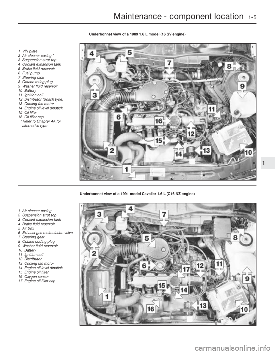
Underbonnet view of a 1989 1.6 L model (16 SV engine)
1 VIN plate
2 Air cleaner casing *
3 Suspension strut top
4 Coolant expansion tank
5 Brake fluid reservoir
6 Fuel pump
7 Steering rack
8 Octane rating plug
9 Washer fluid reservoir
10 Battery
11 Ignition coil
12 Distributor (Bosch type)
13 Cooling fan motor
14 Engine oil level dipstick
15 Oil filter
16 Oil filler cap
* Refer to Chapter 4A for
alternative type
Underbonnet view of a 1991 model Cavalier 1.6 L (C16 NZ engine)
1 Air cleaner casing
2 Suspension strut top
3 Coolant expansion tank
4 Brake fluid reservoir
5 Air box
6 Exhaust gas recirculation valve
7 Steering gear
8 Octane coding plug
9 Washer fluid reservoir
10 Battery
11 Ignition coil
12 Distributor
13 Cooling fan motor
14 Engine oil level dipstick
15 Engine oil filter
16 Oxygen sensor
17 Engine oil filler cap
Page 177 of 525
1•6Maintenance - component location
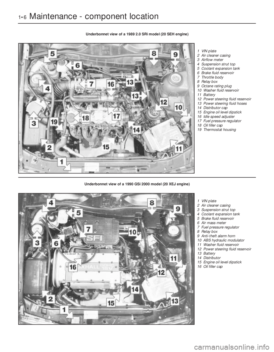
Underbonnet view of a 1989 2.0 SRi model (20 SEH engine)
1 VIN plate
2 Air cleaner casing
3 Airflow meter
4 Suspension strut top
5 Coolant expansion tank
6 Brake fluid reservoir
7 Throttle body
8 Relay box
9 Octane rating plug
10 Washer fluid reservoir
11 Battery
12 Power steering fluid reservoir
13 Power steering fluid hoses
14 Distributor cap
15 Engine oil level dipstick
16 Idle speed adjuster
17 Fuel pressure regulator
18 Oil filler cap
19 Thermostat housing
Underbonnet view of a 1990 GSi 2000 model (20 XEJ engine)
1 VIN plate
2 Air cleaner casing
3 Suspension strut top
4 Coolant expansion tank
5 Brake fluid reservoir
6 Air mass meter
7 Fuel pressure regulator
8 Relay box
9 Anti-theft alarm horn
10 ABS hydraulic modulator
11 Washer fluid reservoir
12 Power steering fluid reservoir
13 Battery
14 Distributor
15 Engine oil level dipstick
16 Oil filler cap
Page 180 of 525
test (refer to Chapter 2A) will provide valuable
information regarding the overall performance
of the main internal components. Such a test
can be used as a basis to decide on the
extent of the work to be carried out. If, for
example, a compression test indicates serious
internal engine wear, conventional
maintenance as described in this Chapter will
not greatly improve the performance of the
engine. It may also prove a waste of time and
money, unless extensive overhaul work is
carried out first.
The following series of operations are those
most often required to improve the
performance of a generally poor-running
engine:Primary operations
a)Clean, inspect and test the battery (See
“Weekly Checks”)
b)Check all the engine related fluids (See
“Weekly Checks”)
c)Check the condition and tension of the
auxiliary drivebelt (Sections 18 and 22, as
appropriate).
d)Renew the spark plugs (Sections 30 and
37, as appropriate).
e)Inspect the distributor cap, rotor arm and
HT leads, as applicable (Section 31).
f)Check the condition of the air filter, and
renew if necessary (Section 27).
g)Check the fuel filter (Section 29).
h)Check the condition of all hoses, and
check for fluid leaks (Section 4).i)Check the idle speed and mixture
settings, as applicable (Section 9).
5If the above operations do not prove fully
effective, carry out the following secondary
operations:
Secondary operations
All items listed under “Primary operations”,
plus the following:
a)Check the charging system (Chapter 5).
b)Check the ignition system (Chapter 5).
c)Check the fuel system (Chapters 4A and
4B).
d)Renew the distributor cap and rotor arm
(Section 31).
e)Renew the ignition HT leads (Section 31).
3Engine oil and filter - renewal
2
1Ideally, the oil should be drained with the
engine hot, just after the vehicle has been
driven.
2On DOHC models, remove the engine
undershield to expose the sump drain plug
and the oil filter.
3Place a container beneath the oil drain plug
at the rear of the sump.
4Remove the oil filler cap from the camshaft
cover, then using a socket or spanner,
unscrew the oil drain plug, and allow the oil to
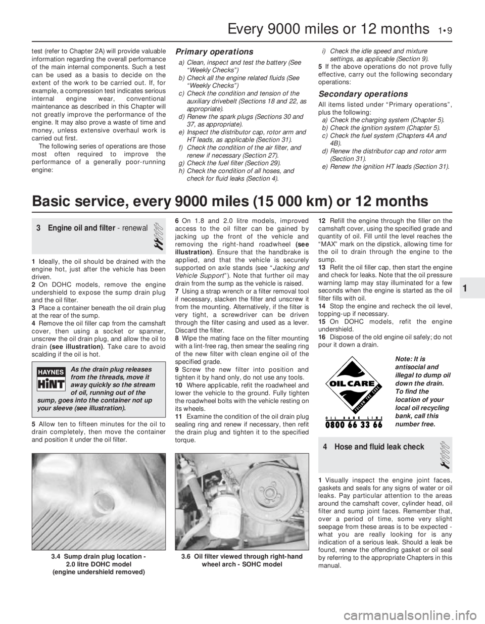
drain (see illustration). Take care to avoid
scalding if the oil is hot.
5Allow ten to fifteen minutes for the oil to
drain completely, then move the container
and position it under the oil filter.6On 1.8 and 2.0 litre models, improved
access to the oil filter can be gained by
jacking up the front of the vehicle and
removing the right-hand roadwheel (see
illustration). Ensure that the handbrake is
applied, and that the vehicle is securely
supported on axle stands (see “Jacking and
Vehicle Support”). Note that further oil may
drain from the sump as the vehicle is raised.
7Using a strap wrench or a filter removal tool
if necessary, slacken the filter and unscrew it
from the mounting. Alternatively, if the filter is
very tight, a screwdriver can be driven
through the filter casing and used as a lever.
Discard the filter.
8Wipe the mating face on the filter mounting
with a lint-free rag, then smear the sealing ring
of the new filter with clean engine oil of the
specified grade.
9Screw the new filter into position and
tighten it by hand only, do not use any tools.
10Where applicable, refit the roadwheel and
lower the vehicle to the ground. Fully tighten
the roadwheel bolts with the vehicle resting on
its wheels.
11Examine the condition of the oil drain plug
sealing ring and renew if necessary, then refit
the drain plug and tighten it to the specified
torque. 12Refill the engine through the filler on the
camshaft cover, using the specified grade and
quantity of oil. Fill until the level reaches the
“MAX” mark on the dipstick, allowing time for
the oil to drain through the engine to the
sump.
13Refit the oil filler cap, then start the engine
and check for leaks. Note that the oil pressure
warning lamp may stay illuminated for a few
seconds when the engine is started as the oil
filter fills with oil.
14Stop the engine and recheck the oil level,
topping-up if necessary.
15On DOHC models, refit the engine
undershield.
16Dispose of the old engine oil safely; do not
pour it down a drain.
4Hose and fluid leak check
1
1Visually inspect the engine joint faces,
gaskets and seals for any signs of water or oil
leaks. Pay particular attention to the areas
around the camshaft cover, cylinder head, oil
filter and sump joint faces. Remember that,
over a period of time, some very slight
seepage from these areas is to be expected -
what you are really looking for is any
indication of a serious leak. Should a leak be
found, renew the offending gasket or oil seal
by referring to the appropriate Chapters in this
manual.
Every 9000 miles or 12 months 1•9
3.6 Oil filter viewed through right-hand
wheel arch - SOHC model3.4 Sump drain plug location -
2.0 litre DOHC model
(engine undershield removed)
1
Basic service, every 9000 miles (15 000 km) or 12 months
As the drain plug releases
from the threads, move it
away quickly so the stream
of oil, running out of the
sump, goes into the container not up
your sleeve (see illustration).
Note: It is
antisocial and
illegal to dump oil
down the drain.
To find the
location of your
local oil recycling
bank, call this
number free.
Page 234 of 525
level in the expansion tank, and top-up if
necessary. Note that the system must be cold
before an accurate level is indicated in the
expansion tank. If the expansion tank cap is
removed while the engine is still warm, cover
the cap with a thick cloth and unscrew the
cap slowly, to gradually relieve the system
pressure. Take care to avoid scalding by
steam or coolant escaping from the
pressurised system.
9On DOHC models, refit the engine
undershield on completion.
5Coolant mixture -general
1It is important to use an antifreeze mixture
in the cooling system all year round, to
prevent corrosion of the alloy engine
components. The coolant mixture should be
made up from clean, preferably soft, tap
water, and a good quality antifreeze
containing corrosion inhibitor. Ensure that the
antifreeze is ethylene glycol based, as the
cheaper methanol based types evaporate
over a period of time.
2The proportions of water and antifreeze
used will depend on the degree of protection
required. A coolant mixture containing 25%
antifreeze should be regarded as the
minimum strength required to maintain good
anti-corrosion properties. Details of the
degree of protection provided against freezing
will be supplied with the antifreeze by the
manufacturers. For absolute protection, use a
50% antifreeze mixture.
3The coolant mixture should be renewed
every two years, as the corrosion inhibitors
will deteriorate with time.
4Before filling the system with fresh coolant,
drain and flush the system, as described in
Sections 2 and 3, and check that all hoses are
secure and that the clips are tight. Antifreeze
has a searching action, and will leak morerapidly than plain water.
5Refill the system as described in Section 4.
All future topping-up should be carried out
using a coolant mixture of the same
proportions as that used to initially fill the
system.
6Do not use antifreeze in the windscreen
wash system, as it will attack the vehicle
paintwork. Note that antifreeze is poisonous,
and must be handled with due care.
6Radiator (manual
transmission) -removal and
refitting
3
Removal
1The radiator can be removed complete with
the coolant fan and shroud if there is no need
to disturb the fan. If desired, the fan and its
shroud can be removed from the radiator,
with reference to Section 12.
2Drain the cooling system, as described in
Section 2.
3Disconnect the radiator top hose and the
expansion tank at the radiator.
4Disconnect the battery negative lead, then
disconnect the wiring from the cooling fan
switch, located at the bottom right-hand side
of the radiator.5Disconnect the cooling fan wiring
connector, noting its location for use when
refitting.
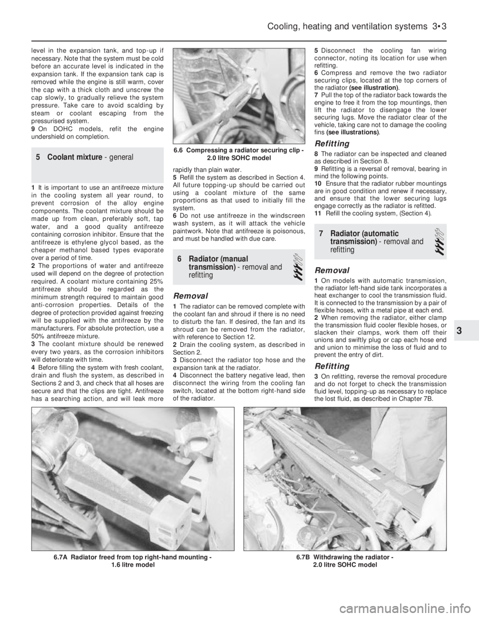
6Compress and remove the two radiator
securing clips, located at the top corners of
the radiator (see illustration).
7Pull the top of the radiator back towards the
engine to free it from the top mountings, then
lift the radiator to disengage the lower
securing lugs. Move the radiator clear of the
vehicle, taking care not to damage the cooling
fins (see illustrations).
Refitting
8The radiator can be inspected and cleaned
as described in Section 8.
9Refitting is a reversal of removal, bearing in
mind the following points.
10Ensure that the radiator rubber mountings
are in good condition and renew if necessary,
and ensure that the lower securing lugs
engage correctly as the radiator is refitted.
11Refill the cooling system, (Section 4).
7Radiator (automatic
transmission) -removal and
refitting
3
Removal
1On models with automatic transmission,
the radiator left-hand side tank incorporates a
heat exchanger to cool the transmission fluid.
It is connected to the transmission by a pair of
flexible hoses, with a metal pipe at each end.
2When removing the radiator, either clamp
the transmission fluid cooler flexible hoses, or
slacken their clamps, work them off their
unions and swiftly plug or cap each hose end
and union to minimise the loss of fluid and to
prevent the entry of dirt.
Refitting
3On refitting, reverse the removal procedure
and do not forget to check the transmission
fluid level, topping-up as necessary to replace
the lost fluid, as described in Chapter 7B.
Cooling, heating and ventilation systems 3•3
6.7B Withdrawing the radiator -
2.0 litre SOHC model6.7A Radiator freed from top right-hand mounting -
1.6 litre model
6.6 Compressing a radiator securing clip -
2.0 litre SOHC model
3
Page 236 of 525
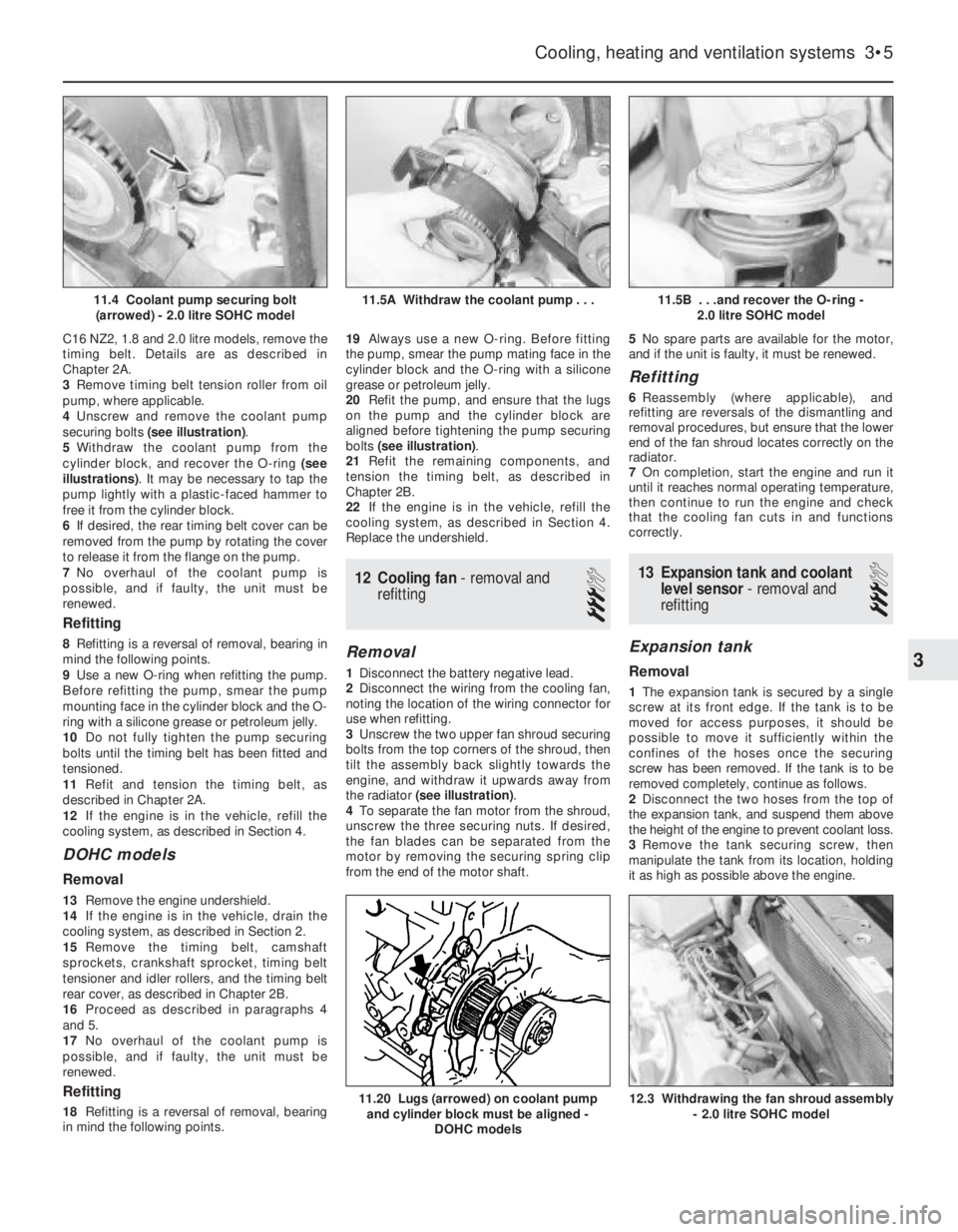
C16 NZ2, 1.8 and 2.0 litre models, remove the
timing belt. Details are as described in
Chapter 2A.
3Remove timing belt tension roller from oil
pump, where applicable.
4Unscrew and remove the coolant pump
securing bolts (see illustration).
5Withdraw the coolant pump from the
cylinder block, and recover the O-ring (see
illustrations). It may be necessary to tap the
pump lightly with a plastic-faced hammer to
free it from the cylinder block.
6If desired, the rear timing belt cover can be
removed from the pump by rotating the cover
to release it from the flange on the pump.
7No overhaul of the coolant pump is
possible, and if faulty, the unit must be
renewed.
Refitting
8Refitting is a reversal of removal, bearing in
mind the following points.
9Use a new O-ring when refitting the pump.
Before refitting the pump, smear the pump
mounting face in the cylinder block and the O-
ring with a silicone grease or petroleum jelly.
10Do not fully tighten the pump securing
bolts until the timing belt has been fitted and
tensioned.
11Refit and tension the timing belt, as
described in Chapter 2A.
12If the engine is in the vehicle, refill the
cooling system, as described in Section 4.
DOHC models
Removal
13Remove the engine undershield.
14If the engine is in the vehicle, drain the
cooling system, as described in Section 2.
15Remove the timing belt, camshaft
sprockets, crankshaft sprocket, timing belt
tensioner and idler rollers, and the timing belt
rear cover, as described in Chapter 2B.
16Proceed as described in paragraphs 4
and 5.
17No overhaul of the coolant pump is
possible, and if faulty, the unit must be
renewed.
Refitting
18Refitting is a reversal of removal, bearing
in mind the following points.19Always use a new O-ring. Before fitting
the pump, smear the pump mating face in the
cylinder block and the O-ring with a silicone
grease or petroleum jelly.
20Refit the pump, and ensure that the lugs
on the pump and the cylinder block are
aligned before tightening the pump securing
bolts (see illustration).
21Refit the remaining components, and
tension the timing belt, as described in
Chapter 2B.
22If the engine is in the vehicle, refill the
cooling system, as described in Section 4.
Replace the undershield.
12Cooling fan - removal and
refitting
3
Removal
1Disconnect the battery negative lead.
2Disconnect the wiring from the cooling fan,
noting the location of the wiring connector for
use when refitting.
3Unscrew the two upper fan shroud securing
bolts from the top corners of the shroud, then
tilt the assembly back slightly towards the
engine, and withdraw it upwards away from
the radiator (see illustration).
4To separate the fan motor from the shroud,
unscrew the three securing nuts. If desired,
the fan blades can be separated from the
motor by removing the securing spring clip
from the end of the motor shaft.5No spare parts are available for the motor,
and if the unit is faulty, it must be renewed.
Refitting
6Reassembly (where applicable), and
refitting are reversals of the dismantling and
removal procedures, but ensure that the lower
end of the fan shroud locates correctly on the
radiator.
7On completion, start the engine and run it
until it reaches normal operating temperature,
then continue to run the engine and check
that the cooling fan cuts in and functions
correctly.
13Expansion tank and coolant
level sensor -removal and
refitting
3
Expansion tank
Removal
1The expansion tank is secured by a single
screw at its front edge. If the tank is to be
moved for access purposes, it should be
possible to move it sufficiently within the
confines of the hoses once the securing
screw has been removed. If the tank is to be
removed completely, continue as follows.
2Disconnect the two hoses from the top of
the expansion tank, and suspend them above
the height of the engine to prevent coolant loss.
3Remove the tank securing screw, then
manipulate the tank from its location, holding
it as high as possible above the engine.
Cooling, heating and ventilation systems 3•5
11.5B . . .and recover the O-ring -
2.0 litre SOHC model
12.3 Withdrawing the fan shroud assembly
- 2.0 litre SOHC model11.20 Lugs (arrowed) on coolant pump
and cylinder block must be aligned -
DOHC models
11.5A Withdraw the coolant pump . . .11.4 Coolant pump securing bolt
(arrowed) - 2.0 litre SOHC model
3
Page 237 of 525
4Position a container beneath the tank, then
disconnect the bottom hose and allow the
contents of the tank to drain into the
container. Suspend the bottom hose as high
as possible above the engine to prevent
coolant loss.
Refitting
5Refitting is a reversal of removal, but on
completion check and if necessary top-up the
coolant level, as described in Section 4. The
coolant drained from the expansion tank
during removal can be re-used, provided it
has not been contaminated.
Coolant level sensor
6The coolant level sensor, where fitted, is an
integral part of the expansion tank cap. If the
level sensor is faulty, the complete cap
assembly must be renewed.
14Temperature gauge sender -
removal and refitting
2
Removal
1The sender is screwed into the inlet
manifold on 1.4 and 1.6 litre models (except
C16 NZ2), and into the thermostat housing
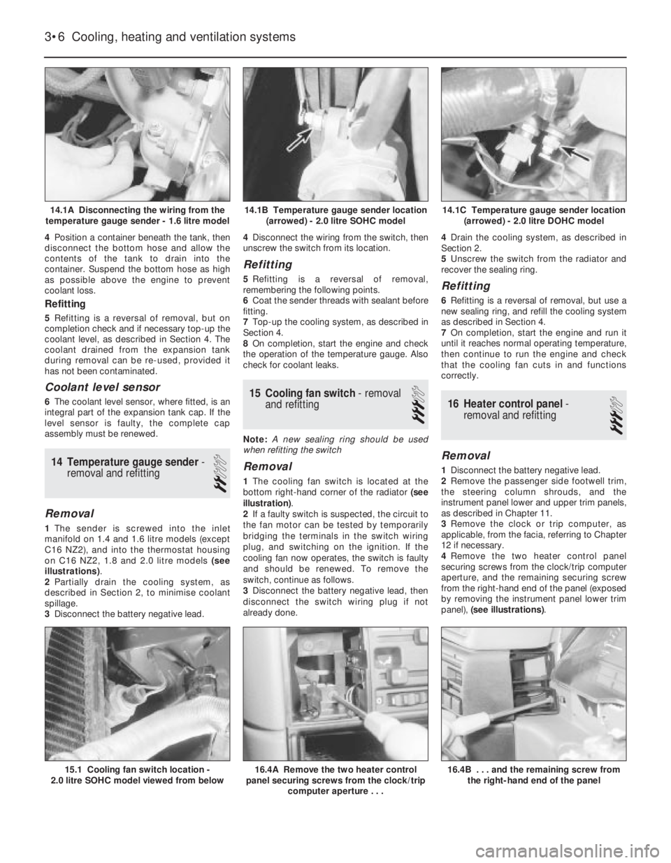
on C16 NZ2, 1.8 and 2.0 litre models (see
illustrations).
2Partially drain the cooling system, as
described in Section 2, to minimise coolant
spillage.
3Disconnect the battery negative lead.4Disconnect the wiring from the switch, then
unscrew the switch from its location.
Refitting
5Refitting is a reversal of removal,
remembering the following points.
6Coat the sender threads with sealant before
fitting.
7Top-up the cooling system, as described in
Section 4.
8On completion, start the engine and check
the operation of the temperature gauge. Also
check for coolant leaks.
15Cooling fan switch -removal
and refitting
3
Note: A new sealing ring should be used
when refitting the switch
Removal
1The cooling fan switch is located at the
bottom right-hand corner of the radiator (see
illustration).
2If a faulty switch is suspected, the circuit to
the fan motor can be tested by temporarily
bridging the terminals in the switch wiring
plug, and switching on the ignition. If the
cooling fan now operates, the switch is faulty
and should be renewed. To remove the
switch, continue as follows.
3Disconnect the battery negative lead, then
disconnect the switch wiring plug if not
already done.4Drain the cooling system, as described in
Section 2.
5Unscrew the switch from the radiator and
recover the sealing ring.
Refitting
6Refitting is a reversal of removal, but use a
new sealing ring, and refill the cooling system
as described in Section 4.
7On completion, start the engine and run it
until it reaches normal operating temperature,
then continue to run the engine and check
that the cooling fan cuts in and functions
correctly.
16Heater control panel -
removal and refitting
3
Removal
1Disconnect the battery negative lead.
2Remove the passenger side footwell trim,
the steering column shrouds, and the
instrument panel lower and upper trim panels,
as described in Chapter 11.
3Remove the clock or trip computer, as
applicable, from the facia, referring to Chapter
12 if necessary.
4Remove the two heater control panel
securing screws from the clock/trip computer
aperture, and the remaining securing screw
from the right-hand end of the panel (exposed
by removing the instrument panel lower trim
panel), (see illustrations).
3•6Cooling, heating and ventilation systems
14.1A Disconnecting the wiring from the
temperature gauge sender - 1.6 litre model14.1C Temperature gauge sender location
(arrowed) - 2.0 litre DOHC model
16.4B . . . and the remaining screw from
the right-hand end of the panel16.4A Remove the two heater control
panel securing screws from the clock/trip
computer aperture . . .15.1 Cooling fan switch location -
2.0 litre SOHC model viewed from below
14.1B Temperature gauge sender location
(arrowed) - 2.0 litre SOHC model
Page 244 of 525
The jack supplied with the vehicle tool kit
should only be used for changing roadwheels.
When carrying out any other kind of work,
raise the vehicle using a hydraulic jack, and
always supplement the jack with axle stands
positioned under the vehicle jacking points.
When jacking up the vehicle with a trolleyjack, position the jack head under one of the
relevant jacking points (note that the jacking
points for use with a hydraulic jack are
different to those for use with the vehicle
jack). Do not jack the vehicle under the sump
or any of the steering or suspension
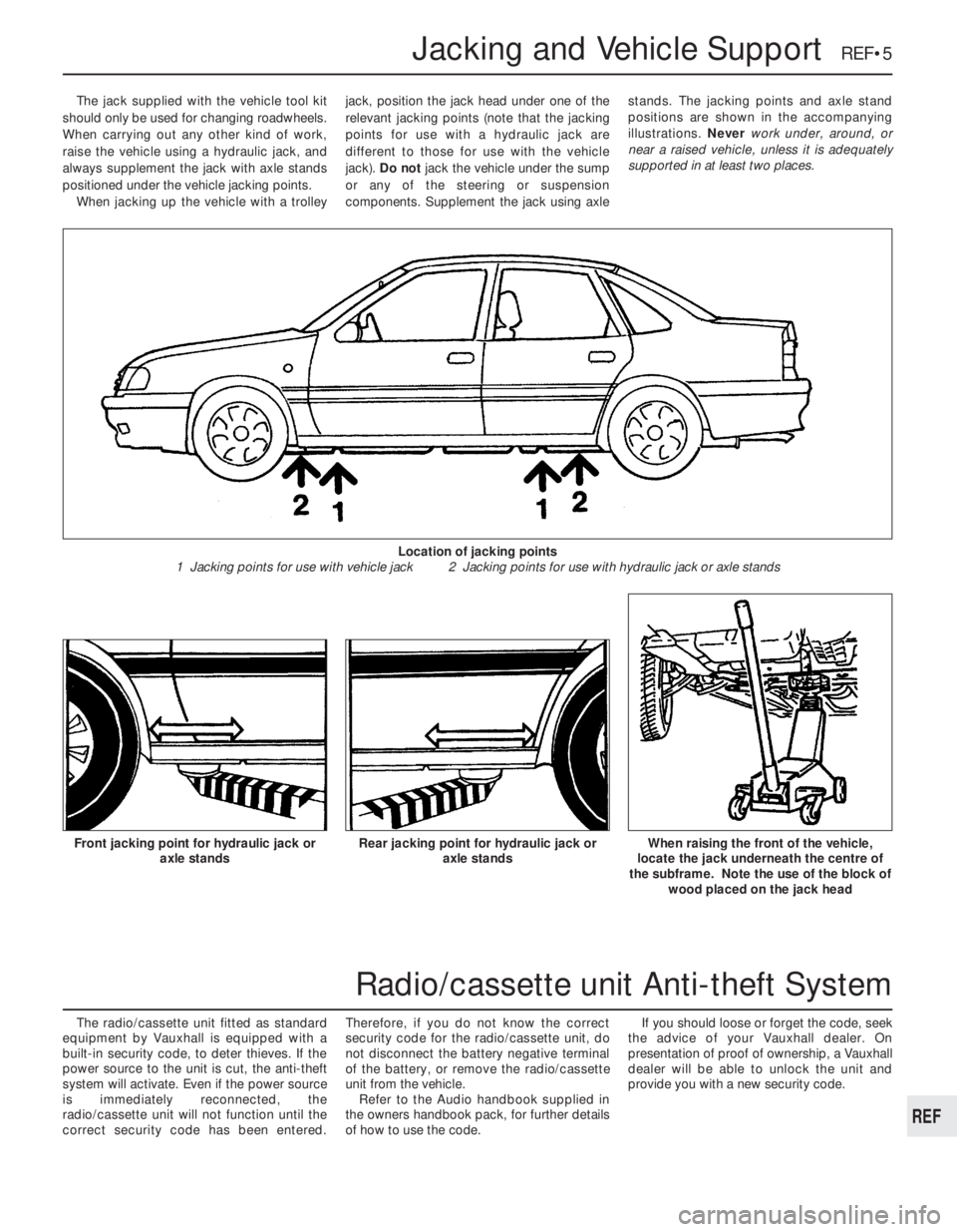
components. Supplement the jack using axlestands. The jacking points and axle stand
positions are shown in the accompanying
illustrations. Never work under, around, or
near a raised vehicle, unless it is adequately
supported in at least two places.
The radio/cassette unit fitted as standard
equipment by Vauxhall is equipped with a
built-in security code, to deter thieves. If the
power source to the unit is cut, the anti-theft
system will activate. Even if the power source
is immediately reconnected, the
radio/cassette unit will not function until the
correct security code has been entered.Therefore, if you do not know the correct
security code for the radio/cassette unit, do
not disconnect the battery negative terminal
of the battery, or remove the radio/cassette
unit from the vehicle.
Refer to the Audio handbook supplied in
the owners handbook pack, for further details
of how to use the code.If you should loose or forget the code, seek
the advice of your Vauxhall dealer. On
presentation of proof of ownership, a Vauxhall
dealer will be able to unlock the unit and
provide you with a new security code.
Jacking and Vehicle Support REF•5
Rear jacking point for hydraulic jack or
axle standsWhen raising the front of the vehicle,
locate the jack underneath the centre of
the subframe. Note the use of the block of
wood placed on the jack headFront jacking point for hydraulic jack or
axle stands
Location of jacking points
1 Jacking points for use with vehicle jack 2 Jacking points for use with hydraulic jack or axle stands
REF
Radio/cassette unit Anti-theft System
Page 262 of 525
Glossary of Technical Terms REF•23
JJump startStarting the engine of a vehicle
with a discharged or weak battery by
attaching jump leads from the weak battery to
a charged or helper battery.
LLoad Sensing Proportioning Valve (LSPV)A
brake hydraulic system control valve that
works like a proportioning valve, but also
takes into consideration the amount of weight
carried by the rear axle.
LocknutA nut used to lock an adjustment
nut, or other threaded component, in place.
For example, a locknut is employed to keep
the adjusting nut on the rocker arm in
position.
LockwasherA form of washer designed to
prevent an attaching nut from working loose.
MMacPherson strutA type of front
suspension system devised by Earle
MacPherson at Ford of England. In its original
form, a simple lateral link with the anti-roll bar
creates the lower control arm. A long strut - an
integral coil spring and shock absorber - is
mounted between the body and the steering
knuckle. Many modern so-called MacPherson
strut systems use a conventional lower A-arm
and don’t rely on the anti-roll bar for location.
MultimeterAn electrical test instrument with
the capability to measure voltage, current and
resistance.
NNOxOxides of Nitrogen. A common toxic
pollutant emitted by petrol and diesel engines
at higher temperatures.
OOhmThe unit of electrical resistance. One
volt applied to a resistance of one ohm will
produce a current of one amp.
OhmmeterAn instrument for measuring
electrical resistance.
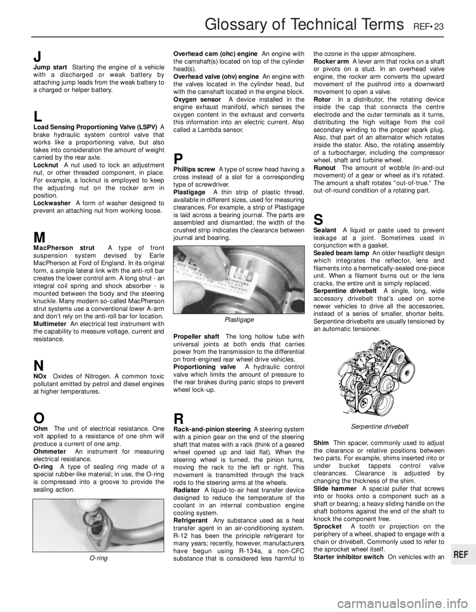
O-ringA type of sealing ring made of a
special rubber-like material; in use, the O-ring
is compressed into a groove to provide the
sealing action.Overhead cam (ohc) engineAn engine with
the camshaft(s) located on top of the cylinder
head(s).
Overhead valve (ohv) engineAn engine with
the valves located in the cylinder head, but
with the camshaft located in the engine block.
Oxygen sensorA device installed in the
engine exhaust manifold, which senses the
oxygen content in the exhaust and converts
this information into an electric current. Also
called a Lambda sensor.
PPhillips screwA type of screw head having a
cross instead of a slot for a corresponding
type of screwdriver.
PlastigageA thin strip of plastic thread,
available in different sizes, used for measuring
clearances. For example, a strip of Plastigage
is laid across a bearing journal. The parts are
assembled and dismantled; the width of the
crushed strip indicates the clearance between
journal and bearing.
Propeller shaftThe long hollow tube with
universal joints at both ends that carries
power from the transmission to the differential
on front-engined rear wheel drive vehicles.
Proportioning valveA hydraulic control
valve which limits the amount of pressure to
the rear brakes during panic stops to prevent
wheel lock-up.
RRack-and-pinion steeringA steering system
with a pinion gear on the end of the steering
shaft that mates with a rack (think of a geared
wheel opened up and laid flat). When the
steering wheel is turned, the pinion turns,
moving the rack to the left or right. This
movement is transmitted through the track
rods to the steering arms at the wheels.
RadiatorA liquid-to-air heat transfer device
designed to reduce the temperature of the
coolant in an internal combustion engine
cooling system.
RefrigerantAny substance used as a heat
transfer agent in an air-conditioning system.
R-12 has been the principle refrigerant for
many years; recently, however, manufacturers
have begun using R-134a, a non-CFC
substance that is considered less harmful tothe ozone in the upper atmosphere.
Rocker armA lever arm that rocks on a shaft
or pivots on a stud. In an overhead valve
engine, the rocker arm converts the upward
movement of the pushrod into a downward
movement to open a valve.
RotorIn a distributor, the rotating device
inside the cap that connects the centre
electrode and the outer terminals as it turns,
distributing the high voltage from the coil
secondary winding to the proper spark plug.
Also, that part of an alternator which rotates
inside the stator. Also, the rotating assembly
of a turbocharger, including the compressor
wheel, shaft and turbine wheel.
RunoutThe amount of wobble (in-and-out
movement) of a gear or wheel as it’s rotated.
The amount a shaft rotates “out-of-true.” The
out-of-round condition of a rotating part.
SSealantA liquid or paste used to prevent
leakage at a joint. Sometimes used in
conjunction with a gasket.
Sealed beam lampAn older headlight design
which integrates the reflector, lens and
filaments into a hermetically-sealed one-piece
unit. When a filament burns out or the lens
cracks, the entire unit is simply replaced.
Serpentine drivebeltA single, long, wide
accessory drivebelt that’s used on some
newer vehicles to drive all the accessories,
instead of a series of smaller, shorter belts.
Serpentine drivebelts are usually tensioned by
an automatic tensioner.
ShimThin spacer, commonly used to adjust
the clearance or relative positions between
two parts. For example, shims inserted into or
under bucket tappets control valve
clearances. Clearance is adjusted by
changing the thickness of the shim.
Slide hammerA special puller that screws
into or hooks onto a component such as a
shaft or bearing; a heavy sliding handle on the
shaft bottoms against the end of the shaft to
knock the component free.
SprocketA tooth or projection on the
periphery of a wheel, shaped to engage with a
chain or drivebelt. Commonly used to refer to
the sprocket wheel itself.
Starter inhibitor switchOn vehicles with an
O-ring
Serpentine drivebelt
Plastigage
REF