1988 OPEL CALIBRA ECO mode
[x] Cancel search: ECO modePage 30 of 525
Centre console-mounted
switches
Removal
5The switches must be removed as a
complete assembly, and cannot be
dismantled. If one of the switches is faulty, the
complete assembly must be renewed.
6Remove the rear section of the centre
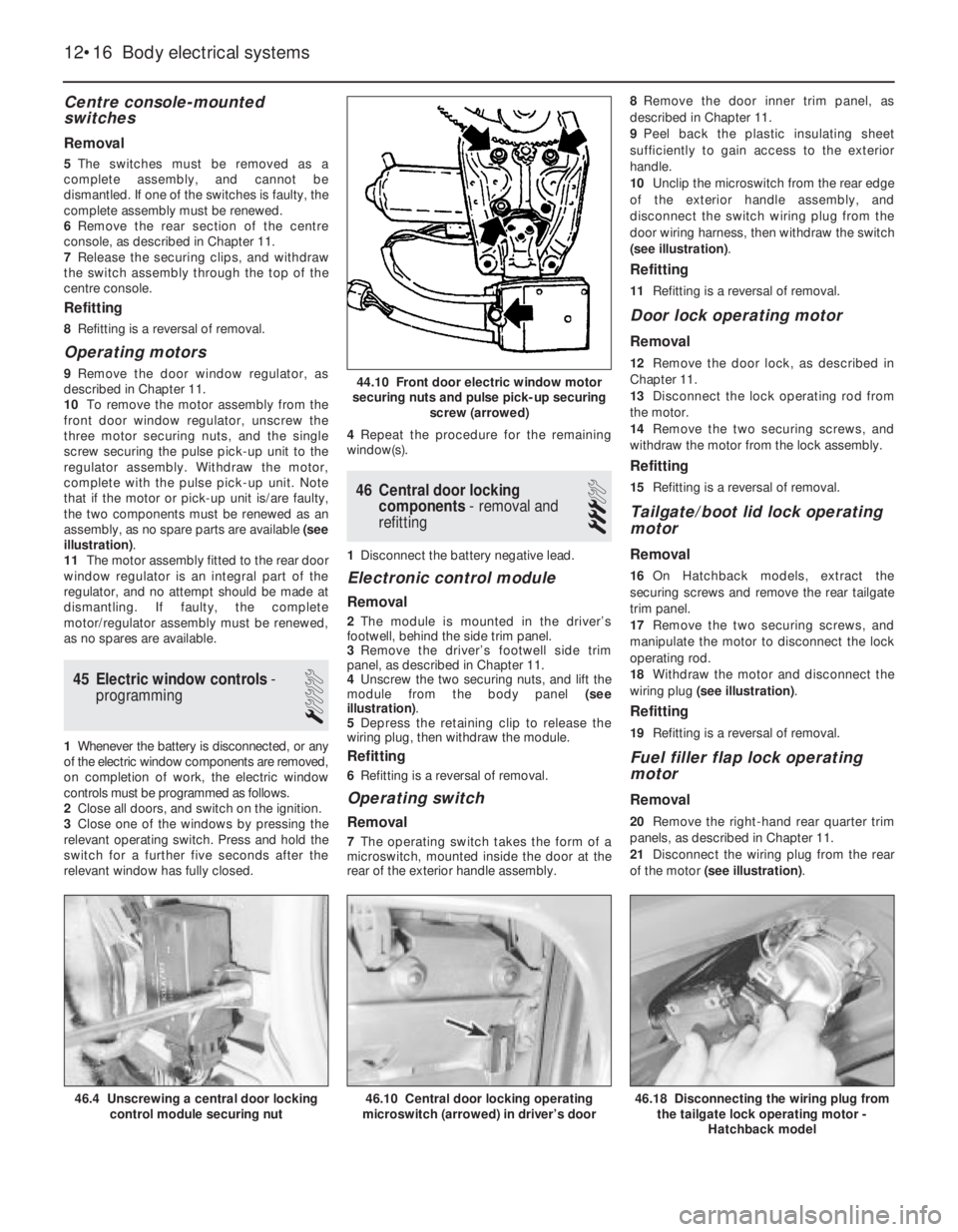
console, as described in Chapter 11.
7Release the securing clips, and withdraw
the switch assembly through the top of the
centre console.
Refitting
8Refitting is a reversal of removal.
Operating motors
9Remove the door window regulator, as
described in Chapter 11.
10To remove the motor assembly from the
front door window regulator, unscrew the
three motor securing nuts, and the single
screw securing the pulse pick-up unit to the
regulator assembly. Withdraw the motor,
complete with the pulse pick-up unit. Note
that if the motor or pick-up unit is/are faulty,
the two components must be renewed as an
assembly, as no spare parts are available (see
illustration).
11The motor assembly fitted to the rear door
window regulator is an integral part of the
regulator, and no attempt should be made at
dismantling. If faulty, the complete
motor/regulator assembly must be renewed,
as no spares are available.
45Electric window controls -
programming
1
1Whenever the battery is disconnected, or any
of the electric window components are removed,
on completion of work, the electric window
controls must be programmed as follows.
2Close all doors, and switch on the ignition.
3Close one of the windows by pressing the
relevant operating switch. Press and hold the
switch for a further five seconds after the
relevant window has fully closed.4Repeat the procedure for the remaining
window(s).
46Central door locking
components -removal and
refitting
3
1Disconnect the battery negative lead.
Electronic control module
Removal
2The module is mounted in the driver’s
footwell, behind the side trim panel.
3Remove the driver’s footwell side trim
panel, as described in Chapter 11.
4Unscrew the two securing nuts, and lift the
module from the body panel (see
illustration).
5Depress the retaining clip to release the
wiring plug, then withdraw the module.
Refitting
6Refitting is a reversal of removal.
Operating switch
Removal
7The operating switch takes the form of a
microswitch, mounted inside the door at the
rear of the exterior handle assembly.8Remove the door inner trim panel, as
described in Chapter 11.
9Peel back the plastic insulating sheet
sufficiently to gain access to the exterior
handle.
10Unclip the microswitch from the rear edge
of the exterior handle assembly, and
disconnect the switch wiring plug from the
door wiring harness, then withdraw the switch
(see illustration).
Refitting
11Refitting is a reversal of removal.
Door lock operating motor
Removal
12Remove the door lock, as described in
Chapter 11.
13Disconnect the lock operating rod from
the motor.
14Remove the two securing screws, and
withdraw the motor from the lock assembly.
Refitting
15Refitting is a reversal of removal.
Tailgate/boot lid lock operating
motor
Removal
16On Hatchback models, extract the
securing screws and remove the rear tailgate
trim panel.
17Remove the two securing screws, and
manipulate the motor to disconnect the lock
operating rod.
18Withdraw the motor and disconnect the
wiring plug (see illustration).
Refitting
19Refitting is a reversal of removal.
Fuel filler flap lock operating
motor
Removal
20Remove the right-hand rear quarter trim
panels, as described in Chapter 11.
21Disconnect the wiring plug from the rear
of the motor (see illustration).
12•16Body electrical systems
44.10 Front door electric window motor
securing nuts and pulse pick-up securing
screw (arrowed)
46.10 Central door locking operating
microswitch (arrowed) in driver’s door46.18 Disconnecting the wiring plug from
the tailgate lock operating motor -
Hatchback model46.4 Unscrewing a central door locking
control module securing nut
Page 33 of 525
53Anti-theft alarm - general
1Certain models are fitted with an anti-theft
alarm as standard equipment.
2The alarm system is triggered by door,
bonnet and boot lid/tailgate mounted
switches, and by ultrasonic sensors mounted
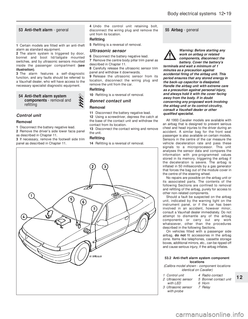
inside the passenger compartment (see
illustration).
3The alarm features a self-diagnostic
function, and any faults should be referred to
a Vauxhall dealer, who will have access to the
necessary specialist diagnostic equipment.
54Anti-theft alarm system
components -removal and
refitting
4
Control unit
Removal
1Disconnect the battery negative lead.
2Remove the driver’s side lower facia panel
as described in Chapter 11.
3If necessary, remove the footwell side trim
panel as described in Chapter 11.4Undo the control unit retaining bolt,
disconnect the wiring plug and remove the
unit from its location.
Refitting
5Refitting is a reversal of removal.
Ultrasonic sensor
6Disconnect the battery negative lead.
7Remove the centre body pillar trim panel as
described in Chapter 11.
8Carefully release the ultrasonic sensor trim
panel and withdraw it downwards.
9Release the ultrasonic sensor from its
location, disconnect the wiring plug and
remove the unit from the car.
Refitting
10Refitting is a reversal of removal.
Bonnet contact unit
Removal
11Disconnect the battery negative lead.
12Using a screwdriver, depress the catch at
the base of the contact unit and withdraw the
contact from its location.
13Disconnect the contact wiring and remove
the unit.
Refitting
14Refitting is a reversal of removal.
55Airbag - general
All 1993 Cavalier models are available with
an airbag that is designed to prevent serious
chest and head injuries to the driver during an
accident. A similar bag for the front seat
passenger is also available on certain models.
Sensors in the centre of the car measure the
vehicle deceleration rate and pass these
signals to a microprocessor. This unit
analyses the sensor data and compares the
information with pre-programmed values
stored in its memory, triggering the airbag if
the deceleration is severe. The airbag is
inflated in 50 milliseconds by a gas generator
that forces the bag out of the module cover in
the centre of the steering wheel.
No repairs are possible on the airbag unit or
its associated parts. The contents of the
following Sections are confined to removal
and refitting of the airbag, purely for access to
other non-related components.
Should a fault be suspected on the airbag
unit, indicated by the warning light on the
instrument panel, or if the car has been
involved in an accident, however minor,
consult a Vauxhall dealer immediately. Do not
attempt to dismantle any of the airbag
components or carry out any work
whatsoever, other than the procedures
described in the following Sections.
On vehicles fitted with a passenger side
airbag, do notfit accessories in the airbag
zone. Items like telephones, cassette storage
boxes, additional mirrors, etc., can be ripped off
and cause serious injury, if the airbag inflates.
Body electrical systems 12•19
12
53.2 Anti-theft alarm system component
locations
(Calibra model shown - component locations
identical on Cavalier)
1 Control unit
2 Ultrasonic sensor
with LED
3 Ultrasonic sensor
with probe4 Radio contact
5 Bonnet contact unit
6 Horn
7 Relay
Warning: Before starting any
work on airbag or related
components, disconnect the
battery. Cover the battery’s
terminals and wait a minimum of 1
minutes as a precaution against
accidental firing of the airbag unit. This
period ensures that any stored energy in
the back-up capacitor is dissipated.
Handle the airbag unit with extreme care
as a precaution against personal injury,
and always hold it with the cover facing
away from the body. If in doubt
concerning any proposed work involving
the airbag unit or its control circuitry,
consult a Vauxhall dealer or other
qualified specialist.
Page 34 of 525

56Airbag unit, drivers side -
removal and refitting
4
Note:On power steering models in particular,
it will be advantageous to jack up the front of
the car and support it on axle stands placed
under the body side members, so that the
steering wheel can be turned more easily.
Removal
1Disconnect the battery negative lead and
cover the battery terminal. Wait a minimum of 1
minute.
2With the steering wheel positioned in the
straight-ahead position, turn it 90°clockwise
so that the left-hand spoke is accessible from
the rear.
3Using a Torx type socket, undo the first
airbag retaining bolt from the rear of the
steering wheel (see illustration).
4Turn the steering wheel 180°anti-clockwise
so that the right-hand spoke is accessible
from the rear.
5Undo the second retaining bolt from the
rear of the steering wheel.
6Return the steering wheel to the
straight-ahead position then carefully lift up
the airbag unit.
7Disconnect the wiring plug and remove the
airbag from the car.
Refitting
8Refitting is a reversal of removal.
57Steering wheel (with airbag)
-removal and refitting
4
Note: Read warning at the beginning of
Section 55, before starting work. A
two-legged puller will be required for this
operation. Note also that the steering wheel is
a very tight fit on the shaft.
Removal
1Remove the airbag unit as described
previously.
2Ensure that the steering wheel is in the
straight ahead position.
3From the centre of the steering wheel
unscrew the two screws securing the airbag
contact unit.4Using a screwdriver, prise back the tabs on
the lockwasher securing the steering wheel
retaining nut.
5Unscrew and remove the steering wheel
retaining nut and the lockwasher.
6Make alignment marks between the
steering wheel and the end of the column
shaft.
7A suitably small two-legged puller must
now be fitted to the steering wheel in order to
pull it from the column shaft.
8Once the steering wheel has been released
from the column shaft, disconnect the horn
wiring and remove the steering wheel.
Refitting
9Begin refitting by positioning the steering
wheel on the column shaft, ensuring that the
marks made on removal are aligned, and that
the wheel correctly engages with the airbag
contact unit. It may be necessary to tap the
steering wheel fully home on the column shaft
using a metal tube and socket.
10Reconnect the horn wiring.
11Refit the lockwasher and the steering
wheel retaining nut, and tighten the nut to the
specified torque. Bend up the lockwasher to
secure.
12Refit the two screws securing the airbag
contact unit.
13Refit the airbag as described previously.
58Airbag contact unit -removal
and refitting
4
Note: Read warning at the beginning of
Section 55, before starting work.
Removal
1Remove the airbag and the steering wheel
as described previously.
2Remove the steering column upper and
lower shrouds, referring to Chapter 10, if
necessary.
3Disconnect the contact unit wiring plug
below the steering column and withdraw the
contact unit from the column, noting its fitted
position as a guide to reassembly (see
illustration).
Refitting
4Before refitting the contact unit, ensure that
the front wheels are in the straight-ahead
position.
5Place the contact unit on the column in the
correct position as noted during removal.
6Route the wiring harness under the steering
column lock/ignition switch and connect the
wiring plug.
7Refit the steering column shrouds.
8Refit the steering wheel and airbag as
described previously.
59Airbag unit, passengers side
- removal and refitting
4
Note: Read warning at the beginning of
Section 55, before starting work.
Removal
1Disconnect the battery, cover the terminals
and wait at least 1 minute.
2Remove the glovebox assembly. Refer to
Chapter 11, for further details if necessary.
3Remove the right hand ventilation air duct.
12•20Body electrical systems
58.3 Airbag contact unit retaining screws
56.3 Airbag, steering wheel and contact unit details
Warning: Read warning at the
beginning of Section 55, before
starting work.
Warning: Stand the unit with the
cover uppermost and do not
expose it to heat sources in
excess of 100ºC. Do not attempt
to open or repair the airbag unit, or apply
any voltage to it. Do not use any airbag
unit that is visibly damaged or has been
tampered with.
Page 35 of 525

4Disconnect the plug connections.
5Unbolt the six M6 nuts from the two side
brackets.
6Remove the airbag unit (see illustration).
Refitting
4Refitting is a reversal of removal.
60Bracket, passenger airbag
unit - removal and refitting
5
Note: Read warning at the beginning of
Section 55, before starting work. This process
involves removal of the windscreen, refer to
Chapter 11, before starting work.
Removal
1Remove the passenger side airbag unit as
described in Section 59.
2Remove the airbag unit cover.
3Remove the water deflector from in front of
the windscreen.
4Remove the windscreen.
5The brackets can now be unbolted.
Refitting
4Refitting is a reversal of removal.
61Airbag control unit - removal
and refitting
4
Note: Read warning at the beginning of
Section 55, before starting work.
Removal
1Disconnect the battery negative lead and
cover the battery terminal to prevent
accidental reconnection.
2Remove the centre console rear section as
described in Chapter 11.
3Disconnect the control unit wiring plug,
then undo the three nuts and remove the unit
from the car (see illustration).
Refitting
4Refitting is a reversal of removal.
62Wiring diagrams -general
1The wiring diagrams are of the current flow
type, each circuit being shown in the simplest
possible fashion. Note that since the diagrams
were originally written in German (to the DIN
standard), all wire colours and abbreviations
used on the diagrams themselves are in
German. Refer to the information given
overleaf for clarification.
2The bottom line of the diagram represents
the “earth” or negative connection; the
numbers below this line are track numbers,
enabling circuits and components to be
located using the key.
3The lines at the top of the diagram
represent “live feed” or positive connection
points. The line marked “30” is live at all
times, that marked “15” is live only when the
ignition is switched on.
4Numbers on the diagram that are framed in
square boxes at the end of a wire show the
track reference number in which that wire is
continued. At the point indicated will be
another framed number referring back to the
circuit just left.
5As an example of how to use the diagrams,
trace with the help of the following text the
reversing lamp switch circuit located between
track reference numbers 496 and 498 on the
1991 model year diagram on page 12•40.
6Starting at the top of track 497, the supply
for the circuit comes from the line “15”,
showing that the circuit is fed only when the
ignition is switched on, through fuse 22 (F22,rated at 10 amps). Note that this fuse can also
protect the feed for several other circuits,
some of which may not be applicable to the
vehicle being worked on.
7If the vehicle in question has a manual
transmission (MT), the circuit continues along
a black wire of 0.75 mm cross-section (as
shown by “SW 0.75” in the wire path), through
terminal 12 of connector X5 to the reversing
lamp switch S7. From the switch the circuit
continues along a white wire, with a black
tracer and of 0.75 mm cross-section (WSSW
0.75), through terminal 2 of connector X5 and
terminal 1 of connector X6, to the reversing
lamp bulbs (E17 and E18). The circuit is
completed by a brown wire from each
bulbholder to earth; in this case the “earth”
wire simply attaches the component to the
nearest piece of metal bodywork, but in other
cases earthing is achieved by the component
mounting and no wire is needed. The diagram
shows, as simply as possible, that when the
switch contacts (which are normally open) are
closed by the driver selecting reverse gear,
current is allowed to flow to earth through the
switch and bulbs causing the reversing lamps
to light.
8If the vehicle in question has automatic
transmission (AT), the circuit differs in that the
“live feed” goes from fuse 22 to terminal “F” of
the transmission selector lever position switch
connector X46 (track reference number 773).
When position “R” is selected, terminals “F”
and “G” are connected so that the circuit feed
continues (back to track reference number
496, the “RFS/reversing lamp” circuit) along
the same route described above for manual
transmission models.
Body electrical systems 12•21
61.3 Airbag control unit details59.6 Removing the passenger side airbag
12
Page 36 of 525

12•22Body electrical systems
Explanations of abbreviations used in wiring diagrams
ABSAnti-lock braking system
ACAir conditioning
AZVTrailer hitch
ATAutomatic transmission
ATCAutomatic temperature control
BRTrip (on-board) computer
CCCheck control system
CRCCruise control
DDiesel
DSTheft protection
DTTurbo Diesel
DWAAnti-theft warning system
DZMTachometer
EFCElectric folding roof (Convertible)
EKSPinch guard (electric windows)
EMPRadio
EUREuronorm (emission control standard)
engine
EZ + ElPlus ignition system (with self-
diagnosis)
EZVEcotronic
FHElectric windows
GBGreat Britain
HSHeated rear window
HWRear window wiper
HZGHeating
HRLLuggage compartment lampINSInstrument panel
IRLCourtesy lamps
KATCatalytic converter
KBSWiring harness
KVContact breaker distributor
L3.1Bosch Jetronic fuel injection system
LCDLiquid crystal display (LCD)
instruments
LHDLeft-hand drive
4WDFour-wheel-drive
LWRHeadlamp aim adjustment
M1.5Bosch Motronic M1.5 engine
management system
M2.5Bosch Motronic M2.5 engine
management system
MOTMotronic (general)
MTManual gearbox
MULMultec fuel injection system
NNorway
NSFront foglamps
NSLRear foglamps
OELOil level/pressure check system
OPTOptional equipment
PBSLPark and brake shift block
(automatic transmission, selector
lever in position ‘P’)P/NPark/neutral (automatic transmission)
POTPotentiometer
RCRear suspension level control
system
RFSReversing lamps
RHDRight-hand drive
SSweden
SDSunroof
SHHeated seats
SRAHeadlamp washers and wipers
TANKFuel level sender unit
TDTurbo Diesel
TEMPTemperature gauge
TFLDaytime driving lamps
TKSCourtesy lamp (door pillar) switches
TSZITransistorised ignition (inductive-
triggered) system
VGSCarburettor
WEGOdometer frequency/roadspeed
sensor
WHRRear suspension level control
system
WSWarning buzzer
ZVCentral locking
ZYLCylinder
Colour codes
BLBlue
HBLLight blue
BRBrown
GEYellow
GRGrey
GNGreenRTRed
WSWhite
SWBlack
LILilac
VIViolet
Wiring identification
Example: GEWS 1.5
GE -Wire basic colour
WS -Wire tracer colour
1.5 -Wire cross-section in mm
2
Note: Not all items shown are fitted to all models. Refer to Section 62 (Chapter 12) for details of diagram usage.
Page 39 of 525
Wiring diagrams 12•25
12
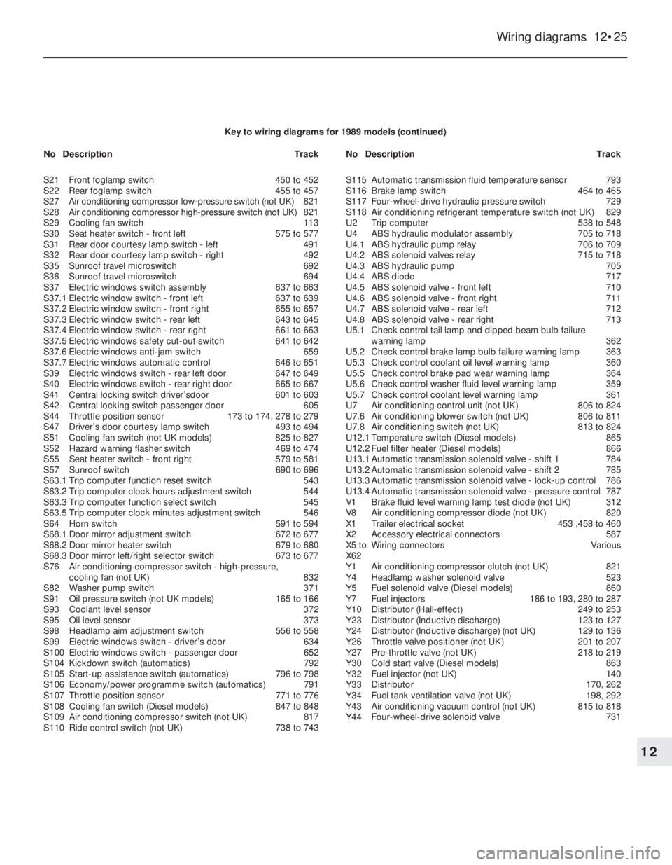
Key to wiring diagrams for 1989 models (continued)
S21Front foglamp switch450 to 452
S22Rear foglamp switch455 to 457
S27Air conditioning compressor low-pressure switch (not UK)821
S28Air conditioning compressor high-pressure switch (not UK)821
S29Cooling fan switch113
S30Seat heater switch - front left575 to 577
S31Rear door courtesy lamp switch - left491
S32Rear door courtesy lamp switch - right492
S35Sunroof travel microswitch692
S36Sunroof travel microswitch694
S37Electric windows switch assembly637 to 663
S37.1Electric window switch - front left637 to 639
S37.2Electric window switch - front right655 to 657
S37.3Electric window switch - rear left643 to 645
S37.4Electric window switch - rear right661 to 663
S37.5Electric windows safety cut-out switch641 to 642
S37.6Electric windows anti-jam switch659
S37.7Electric windows automatic control646 to 651
S39Electric windows switch - rear left door647 to 649
S40Electric windows switch - rear right door665 to 667
S41Central locking switch driver’sdoor601 to 603
S42Central locking switch passenger door605
S44Throttle position sensor173 to 174, 278 to 279
S47Driver’s door courtesy lamp switch493 to 494
S51Cooling fan switch (not UK models)825 to 827
S52Hazard warning flasher switch469 to 474
S55Seat heater switch - front right579 to 581
S57Sunroof switch690 to 696
S63.1Trip computer function reset switch543
S63.2Trip computer clock hours adjustment switch544
S63.3Trip computer function select switch545
S63.5Trip computer clock minutes adjustment switch546
S64Horn switch591 to 594
S68.1Door mirror adjustment switch672 to 677
S68.2Door mirror heater switch679 to 680
S68.3Door mirror left/right selector switch673 to 677
S76Air conditioning compressor switch -high-pressure,
cooling fan (not UK)832
S82Washer pump switch371
S91Oil pressure switch (not UK models)165 to 166
S93Coolant level sensor372
S95Oil level sensor373
S98Headlamp aim adjustment switch556 to 558
S99Electric windows switch - driver’s door634
S100Electric windows switch -passenger door652
S104Kickdown switch (automatics)792
S105Start-up assistance switch (automatics)796 to 798
S106Economy/power programme switch (automatics)791
S107Throttle position sensor 771 to 776
S108Cooling fan switch (Diesel models)847 to 848
S109Air conditioning compressor switch (not UK)817
S110Ride control switch (not UK)738 to 743S115Automatic transmission fluid temperature sensor793
S116Brake lamp switch464 to 465
S117Four-wheel-drive hydraulic pressure switch729
S118Air conditioning refrigerant temperature switch (not UK)829
U2Trip computer538 to 548
U4ABS hydraulic modulator assembly705 to 718
U4.1ABS hydraulic pump relay706 to 709
U4.2ABS solenoid valves relay715 to 718
U4.3ABS hydraulic pump705
U4.4ABS diode717
U4.5ABS solenoid valve - front left710
U4.6ABS solenoid valve - front right711
U4.7ABS solenoid valve - rear left712
U4.8ABS solenoid valve - rear right713
U5.1Check control tail lamp and dipped beam bulb failure
warning lamp362
U5.2Check control brake lamp bulb failure warning lamp 363
U5.3Check control coolant oil level warning lamp360
U5.5Check control brake pad wear warning lamp364
U5.6Check control washer fluid level warning lamp359
U5.7Check control coolant level warning lamp361
U7Air conditioning control unit (not UK)806 to 824
U7.6Air conditioning blower switch (not UK)806 to 811
U7.8Air conditioning switch (not UK)813 to 824
U12.1Temperature switch (Diesel models)865
U12.2Fuel filter heater (Diesel models)866
U13.1Automatic transmission solenoid valve -shift 1784
U13.2Automatic transmission solenoid valve - shift 2785
U13.3Automatic transmission solenoid valve - lock-up control786
U13.4Automatic transmission solenoid valve - pressure control787
V1Brake fluid level warning lamp test diode (not UK)312
V8 Air conditioning compressor diode (not UK)820
X1Trailer electrical socket453 ,458 to 460
X2Accessory electrical connectors587
X5 toWiring connectorsVarious
X62
Y1Air conditioning compressor clutch (not UK)821
Y4Headlamp washer solenoid valve523
Y5Fuel solenoid valve (Diesel models)860
Y7Fuel injectors186 to 193, 280 to 287
Y10Distributor (Hall-effect)249 to 253
Y23Distributor (Inductive discharge)123 to 127
Y24Distributor (Inductive discharge) (not UK)129 to 136
Y26Throttle valve positioner (not UK)201 to 207
Y27Pre-throttle valve (not UK)218 to 219
Y30Cold start valve (Diesel models)863
Y32Fuel injector (not UK)140
Y33Distributor170, 262
Y34Fuel tank ventilation valve (not UK)198, 292
Y43Air conditioning vacuum control (not UK)815 to 818
Y44Four-wheel-drive solenoid valve731 NoDescriptionTrackNoDescriptionTrack
Page 54 of 525
12•40Wiring diagrams
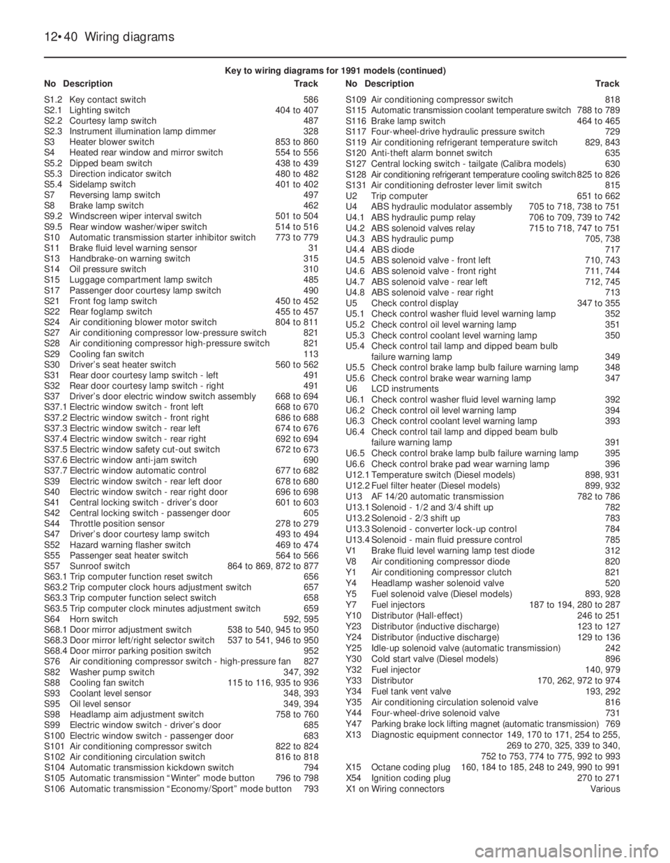
Key to wiring diagrams for 1991 models (continued)
NoDescriptionTrackNoDescriptionTrack
S1.2Key contact switch586
S2.1Lighting switch404 to 407
S2.2Courtesy lamp switch487
S2.3Instrument illumination lamp dimmer328
S3Heater blower switch853 to 860
S4Heated rear window and mirror switch554 to 556
S5.2Dipped beam switch438 to 439
S5.3Direction indicator switch480 to 482
S5.4Sidelamp switch401 to 402
S7Reversing lamp switch497
S8Brake lamp switch462
S9.2Windscreen wiper interval switch501 to 504
S9.5Rear window washer/wiper switch514 to 516
S10Automatic transmission starter inhibitor switch773 to 779
S11Brake fluid level warning sensor31
S13Handbrake-on warning switch315
S14Oil pressure switch310
S15Luggage compartment lamp switch485
S17Passenger door courtesy lamp switch490
S21Front fog lamp switch450 to 452
S22Rear foglamp switch455 to 457
S24Air conditioning blower motor switch804 to 811
S27Air conditioning compressor low-pressure switch821
S28Air conditioning compressor high-pressure switch821
S29Cooling fan switch113
S30Driver’s seat heater switch560 to 562
S31Rear door courtesy lamp switch - left491
S32Rear door courtesy lamp switch - right491
S37Driver’s door electric window switch assembly668 to 694
S37.1Electric window switch - front left668 to 670
S37.2Electric window switch - front right686 to 688
S37.3Electric window switch - rear left674 to 676
S37.4Electric window switch - rear right692 to 694
S37.5Electric window safety cut-out switch672 to 673
S37.6Electric window anti-jam switch690
S37.7Electric window automatic control677 to 682
S39Electric window switch - rear left door678 to 680
S40Electric window switch - rear right door696 to 698
S41Central locking switch - driver’s door601 to 603
S42Central locking switch - passenger door605
S44Throttle position sensor278 to 279
S47Driver’s door courtesy lamp switch493 to 494
S52Hazard warning flasher switch469 to 474
S55Passenger seat heater switch564 to 566
S57Sunroof switch864 to 869, 872 to 877
S63.1Trip computer function reset switch656
S63.2Trip computer clock hours adjustment switch657
S63.3Trip computer function select switch658
S63.5Trip computer clock minutes adjustment switch659
S64Horn switch592, 595
S68.1Door mirror adjustment switch538 to 540, 945 to 950
S68.3Door mirror left/right selector switch537 to 541, 946 to 950
S68.4Door mirror parking position switch952
S76Air conditioning compressor switch - high-pressure fan827
S82Washer pump switch347, 392
S88Cooling fan switch115 to 116, 935 to 936
S93Coolant level sensor348, 393
S95Oil level sensor349, 394
S98Headlamp aim adjustment switch758 to 760
S99Electric window switch - driver’s door685
S100Electric window switch - passenger door683
S101Air conditioning compressor switch822 to 824
S102Air conditioning circulation switch816 to 818
S104Automatic transmission kickdown switch794
S105Automatic transmission “Winter” mode button796 to 798
S106Automatic transmission “Economy/Sport” mode button793S109Air conditioning compressor switch818
S115Automatic transmission coolant temperature switch788 to 789
S116Brake lamp switch464 to 465
S117Four-wheel-drive hydraulic pressure switch729
S119Air conditioning refrigerant temperature switch829, 843
S120Anti-theft alarm bonnet switch635
S127Central locking switch - tailgate (Calibra models)630
S128Air conditioning refrigerant temperature cooling switch825 to 826
S131Air conditioning defroster lever limit switch815
U2Trip computer651 to 662
U4ABS hydraulic modulator assembly705 to 718, 738 to 751
U4.1ABS hydraulic pump relay706 to 709, 739 to 742
U4.2ABS solenoid valves relay715 to 718, 747 to 751
U4.3ABS hydraulic pump705, 738
U4.4ABS diode717
U4.5ABS solenoid valve - front left710, 743
U4.6ABS solenoid valve - front right711, 744
U4.7ABS solenoid valve - rear left712, 745
U4.8ABS solenoid valve - rear right713
U5Check control display347 to 355
U5.1Check control washer fluid level warning lamp352
U5.2Check control oil level warning lamp351
U5.3Check control coolant level warning lamp350
U5.4Check control tail lamp and dipped beam bulb
failure warning lamp349
U5.5Check control brake lamp bulb failure warning lamp348
U5.6Check control brake wear warning lamp347
U6LCD instruments
U6.1Check control washer fluid level warning lamp392
U6.2Check control oil level warning lamp394
U6.3Check control coolant level warning lamp393
U6.4Check control tail lamp and dipped beam bulb
failure warning lamp391
U6.5Check control brake lamp bulb failure warning lamp395
U6.6Check control brake pad wear warning lamp396
U12.1Temperature switch (Diesel models)898, 931
U12.2Fuel filter heater (Diesel models)899, 932
U13AF14/20automatic transmission782 to 786
U13.1Solenoid - 1/2 and 3/4 shift up782
U13.2Solenoid - 2/3 shift up783
U13.3Solenoid - converter lock-up control784
U13.4Solenoid - main fluid pressure control785
V1Brake fluid level warning lamp test diode312
V8Air conditioning compressor diode820
Y1Air conditioning compressor clutch821
Y4Headlamp washer solenoid valve520
Y5Fuel solenoid valve (Diesel models)893, 928
Y7Fuel injectors187 to 194, 280 to 287
Y10Distributor (Hall-effect)246 to 251
Y23Distributor (inductive discharge)123 to 127
Y24Distributor (inductive discharge)129 to 136
Y25Idle-up solenoid valve (automatic transmission)242
Y30Cold start valve (Diesel models)896
Y32Fuel injector140, 979
Y33Distributor170, 262, 972 to 974
Y34Fuel tank vent valve193, 292
Y35Air conditioning circulation solenoid valve816
Y44Four-wheel-drive solenoid valve731
Y47Parking brake lock lifting magnet (automatic transmission)769
X13Diagnostic equipment connector149, 170 to 171, 254 to 255,
269 to 270, 325, 339 to 340,
752 to 753, 774 to 775, 992 to 993
X15Octane coding plug160, 184 to 185, 248 to 249, 990 to 991
X54Ignition coding plug270 to 271
X1 onWiring connectorsVarious
Page 71 of 525
Wiring diagrams 12•57
12
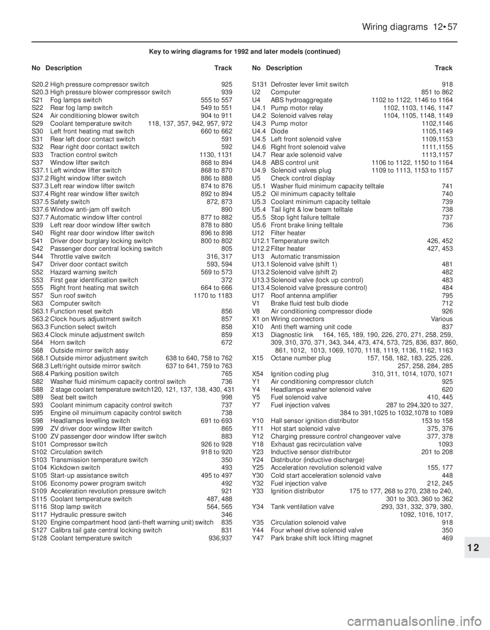
Key to wiring diagrams for 1992 and later models (continued)
NoDescriptionTrackNoDescriptionTrack
S20.2High pressure compressor switch925
S20.3High pressure blower compressor switch939
S21Fog lamps switch555 to 557
S22Rear fog lamp switch549 to 551
S24Air conditioning blower switch904 to 911
S29Coolant temperature switch118, 137, 357, 942, 957, 972
S30Left front heating mat switch660 to 662
S31Rear left door contact switch591
S32Rear right door contact switch592
S33Traction control switch1130, 1131
S37Window lifter switch868 to 894
S37.1Left window lifter switch868 to 870
S37.2Right window lifter switch886 to 888
S37.3Left rear window lifter switch874 to 876
S37.4Right rear window lifter switch892 to 894
S37.5Safety switch872, 873
S37.6Window anti-jam off switch890
S37.7Automatic window lifter control877 to 882
S39Left rear door window lifter switch878 to 880
S40Right rear door window lifter switch896 to 898
S41Driver door burglary locking switch800 to 802
S42Passenger door central locking switch805
S44Throttle valve switch316, 317
S47Driver door contact switch593, 594
S52Hazard warning switch569 to 573
S53First gear identification switch372
S55Right front heating mat switch664 to 666
S57Sun roof switch1170 to 1183
S63Computer switch
S63.1Function reset switch856
S63.2Clock hours adjustment switch857
S63.3Function select switch858
S63.4Clock minute adjustment switch859
S64Horn switch672
S68Outside mirror switch assy
S68.1Outside mirror adjustment switch638 to 640, 758 to 762
S68.3Left/right outside mirror switch637 to 641, 759 to 763
S68.4Parking position switch765
S82Washer fluid minimum capacity control switch736
S882 stage coolant temperature switch120, 121, 137, 138, 430, 431
S89Seat belt switch998
S93Coolant minimum capacity control switch737
S95Engine oil minuimum capacity control switch738
S98Headlamps levelling switch691 to 693
S99ZV driver door window lifter switch865
S100ZV passenger door window lifter switch883
S101Compressor switch926 to 928
S102Circulation switch918 to 920
S103Transmission temperature switch350
S104Kickdown switch493
S105Start-up assistance switch495 to 497
S106Economy power program switch492
S109Acceleration revolution pressure switch921
S115Coolant temperature switch487, 488
S116Stop lamp switch564, 565
S117Hydraulic pressure switch346
S120Engine compartment hood (anti-theft warning unit) switch835
S127Calibra tail gate central locking switch831
S128Coolant temperature switch936,937S131Defroster lever limit switch918
U2Computer851 to 862
U4ABS hydroaggregate1102 to 1122, 1146 to 1164
U4.1Pump motor relay1102, 1103, 1146, 1147
U4.2Solenoid valves relay1104, 1105, 1148, 1149
U4.3Pump motor1102,1146
U4.4Diode1105,1149
U4.5Left front solenoid valve1109,1153
U4.6Right front solenoid valve1111,1155
U4.7Rear axle solenoid valve1113,1157
U4.8ABS control unit1106 to 1122, 1150 to 1164
U4.9Solenoid valves plug1109 to 1113, 1153 to 1157
U5Check control display
U5.1Washer fluid minimum capacity telltale741
U5.2Oil minimum capacity telltale740
U5.3Coolant minimum capacity telltale739
U5.4Tail light & low beam telltale738
U5.5Stop light failure telltale737
U5.6Front brake lining telltale736
U12Filter heater
U12.1Temperature switch426, 452
U12.2Filter heater427, 453
U13Automatic transmission
U13.1Solenoid valve (shift 1)481
U13.2Solenoid valve (shift 2)482
U13.3Solenoid valve (lock up control)483
U13.4Solenoid valve (pressure control)484
U17Roof antenna amplifier795
V1Brake fluid test bulb diode712
V8Air conditioning compressor diode926
X1 onWiring connectorsVarious
X10Anti theft warning unit code837
X13Diagnostic link164, 165, 189, 190, 226, 270, 271, 258, 259,
309, 310, 370, 371, 343, 344, 473, 474, 573, 725, 836, 837, 860,
861, 1012, 1013, 1069, 1070, 1118, 1119, 1136, 1162, 1163
X15Octane number plug157, 158, 182, 183, 225, 226,
257, 258, 284, 285
X54Ignition coding plug310, 311, 1014, 1070, 1071
Y1Air conditioning compressor clutch925
Y4Headlamps washer solenoid valve620
Y5Fuel solenoid valve410, 445
Y7Fuel injection valves287 to 294,320 to 327,
384 to 391,1025 to 1032,1078 to 1089
Y10Hall sensor ignition distributor153 to 158
Y11Hot start solenoid valve375, 376
Y12Charging pressure control changeover valve377, 378
Y18Exhaust gas recirculation valve1093
Y23Inductive sensor distributor201 to 208
Y24Distributor (inductive discharge)
Y25Acceleration revolution solenoid valve155, 177
Y30Cold start acceleration solenoid valve 448
Y32Fuel injection valve212, 245
Y33Ignition distributor175 to 177, 268 to 270, 238 to 240,
301 to 303, 360 to 362
Y34Tank ventilation valve293, 331, 332, 379, 380,
1092, 1016, 1017,
Y35Circulation solenoid valve918
Y44Four wheel drive solenoid valve350
Y47Park brake shift lock lifting magnet469