1988 OPEL CALIBRA ECO mode
[x] Cancel search: ECO modePage 134 of 525
5If the ‘ABS’ symbol, in the instrument panel
stays lit after approximately 4 seconds, or if it
comes on sporadically or stays on whilst
driving, there is a fault in the system. Should
this occur, it is recommended that a complete
test is carried out by a Vauxhall dealer, who
will have the necessary specialist diagnostic
equipment. Due to the special equipment
required, it is not practical for the DIY
mechanic to carry out the test procedure.
6To prevent possible damage to the
electronic control unit, always disconnect the
control unit wiring plug before carrying out
electrical welding work.
7It is recommended that the control unit is
removed if the vehicle is being subjected to
high temperatures, like for instance, during
certain paint-drying processes.
8If using steam cleaning equipment, do not
aim the water/steam jet directly at the control
unit.
9Do not disconnect the control unit wiring
plug with the ignition switched on.
10Do not use a battery booster to start the
engine.
11After working on the ABS components,
ensure that all wiring plugs are correctly
reconnected, and have the complete system
tested by a Vauxhall dealer, at the earliest
opportunity.
12All models up to 1991 that were fitted with
ABS, used the ABS-2E system. From 1992
onwards an ABS-2EH system was fitted,
which can be identified by the location of the
electronic control module, which is bolted to
the hydraulic modulator.
13The main differences between the two
systems are in the electrical components and
circuits, the most obvious of these being
omission of the surge arrester relay on the
2EH system.
3Hydraulic system - bleeding
2
General
1If any of the hydraulic components in the
braking system have been removed or
disconnected, or if the fluid level in the
reservoir has been allowed to fall appreciably,
it is certain that air will have entered into the
system. The removal of all this air from the
hydraulic system is essential if the brakes are
to function correctly, and the process of
removing it is known as bleeding.
2Where an operation has only affected one
circuit of the hydraulic system (the system issplit diagonally on non-ABS models, and front
and rear on ABS models), then it will only be
necessary to bleed the relevant circuit. If the
master cylinder has been disconnected and
reconnected, or the fluid level has been
allowed to fall appreciably, then the complete
system must be bled.
3One of three methods can be used to bleed
the system, although Vauxhall recommend
the use of a pressure bleeding kit.
Bleeding - two-man method
4Obtain a clean jar, and a length of rubber or
plastic bleed tubing that will fit the bleed
screws tightly. The help of an assistant will be
required.
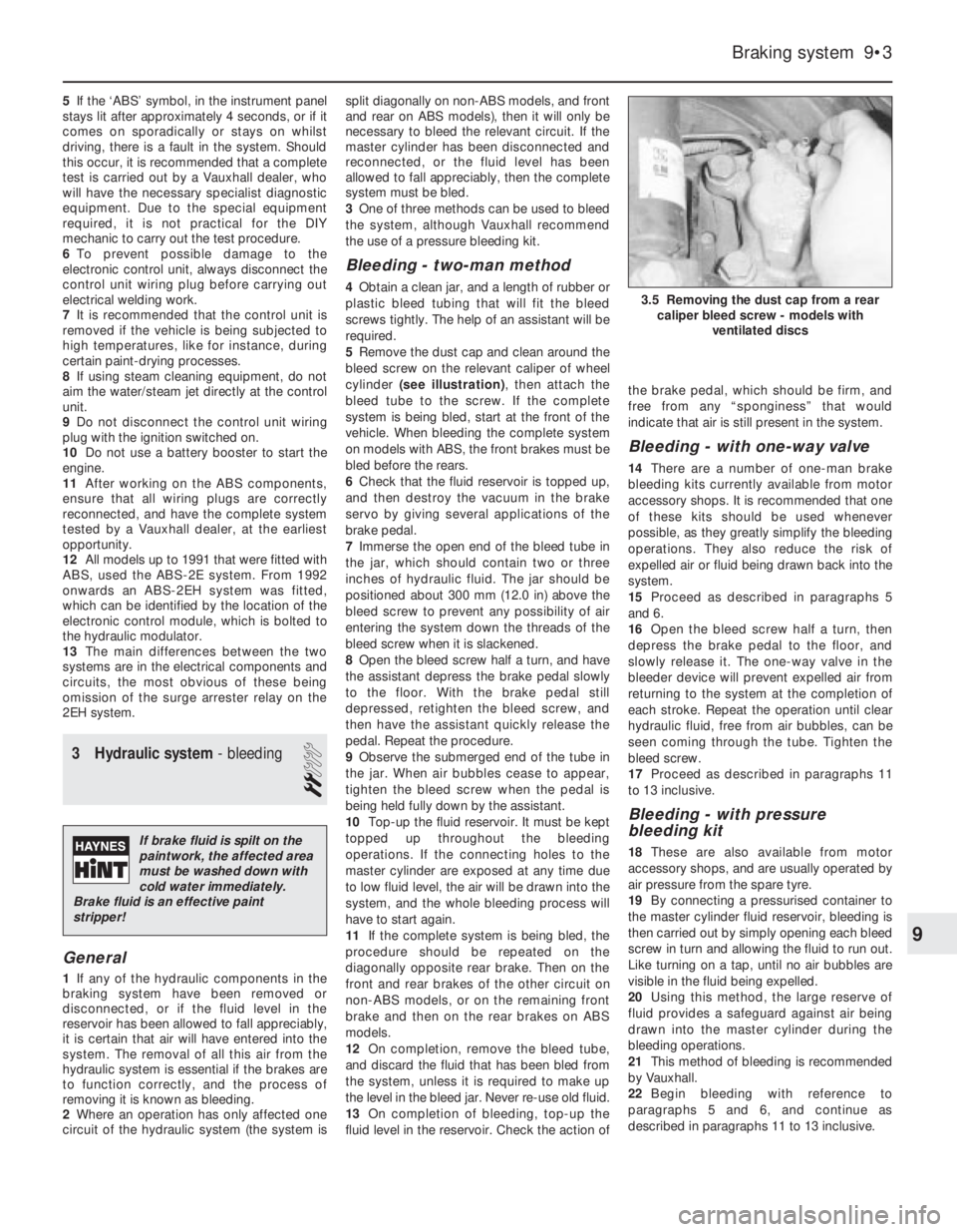
5Remove the dust cap and clean around the
bleed screw on the relevant caliper of wheel
cylinder (see illustration), then attach the
bleed tube to the screw. If the complete
system is being bled, start at the front of the
vehicle. When bleeding the complete system
on models with ABS, the front brakes must be
bled before the rears.
6Check that the fluid reservoir is topped up,
and then destroy the vacuum in the brake
servo by giving several applications of the
brake pedal.
7Immerse the open end of the bleed tube in
the jar, which should contain two or three
inches of hydraulic fluid. The jar should be
positioned about 300 mm (12.0 in) above the
bleed screw to prevent any possibility of air
entering the system down the threads of the
bleed screw when it is slackened.
8Open the bleed screw half a turn, and have
the assistant depress the brake pedal slowly
to the floor. With the brake pedal still
depressed, retighten the bleed screw, and
then have the assistant quickly release the
pedal. Repeat the procedure.
9Observe the submerged end of the tube in
the jar. When air bubbles cease to appear,
tighten the bleed screw when the pedal is
being held fully down by the assistant.
10Top-up the fluid reservoir. It must be kept
topped up throughout the bleeding
operations. If the connecting holes to the
master cylinder are exposed at any time due
to low fluid level, the air will be drawn into the
system, and the whole bleeding process will
have to start again.
11If the complete system is being bled, the
procedure should be repeated on the
diagonally opposite rear brake. Then on the
front and rear brakes of the other circuit on
non-ABS models, or on the remaining front
brake and then on the rear brakes on ABS
models.
12On completion, remove the bleed tube,
and discard the fluid that has been bled from
the system, unless it is required to make up
the level in the bleed jar. Never re-use old fluid.
13On completion of bleeding, top-up the
fluid level in the reservoir. Check the action ofthe brake pedal, which should be firm, and
free from any “sponginess” that would
indicate that air is still present in the system.
Bleeding - with one-way valve
14There are a number of one-man brake
bleeding kits currently available from motor
accessory shops. It is recommended that one
of these kits should be used whenever
possible, as they greatly simplify the bleeding
operations. They also reduce the risk of
expelled air or fluid being drawn back into the
system.
15Proceed as described in paragraphs 5
and 6.
16Open the bleed screw half a turn, then
depress the brake pedal to the floor, and
slowly release it. The one-way valve in the
bleeder device will prevent expelled air from
returning to the system at the completion of
each stroke. Repeat the operation until clear
hydraulic fluid, free from air bubbles, can be
seen coming through the tube. Tighten the
bleed screw.
17Proceed as described in paragraphs 11
to 13 inclusive.
Bleeding - with pressure
bleeding kit
18These are also available from motor
accessory shops, and are usually operated by
air pressure from the spare tyre.
19By connecting a pressurised container to
the master cylinder fluid reservoir, bleeding is
then carried out by simply opening each bleed
screw in turn and allowing the fluid to run out.
Like turning on a tap, until no air bubbles are
visible in the fluid being expelled.
20Using this method, the large reserve of
fluid provides a safeguard against air being
drawn into the master cylinder during the
bleeding operations.
21This method of bleeding is recommended
by Vauxhall.
22Begin bleeding with reference to
paragraphs 5 and 6, and continue as
described in paragraphs 11 to 13 inclusive.
Braking system 9•3
3.5 Removing the dust cap from a rear
caliper bleed screw - models with
ventilated discs
9
If brake fluid is spilt on the
paintwork, the affected area
must be washed down with
cold water immediately.
Brake fluid is an effective paint
stripper!
Page 136 of 525
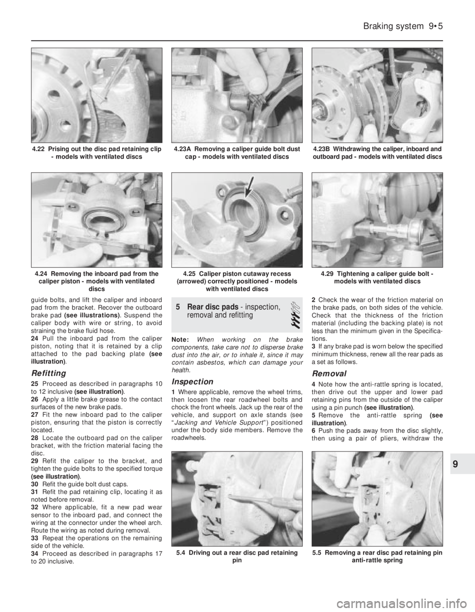
guide bolts, and lift the caliper and inboard
pad from the bracket. Recover the outboard
brake pad (see illustrations). Suspend the
caliper body with wire or string, to avoid
straining the brake fluid hose.
24Pull the inboard pad from the caliper
piston, noting that it is retained by a clip
attached to the pad backing plate (see
illustration).
Refitting
25Proceed as described in paragraphs 10
to 12 inclusive (see illustration).
26Apply a little brake grease to the contact
surfaces of the new brake pads.
27Fit the new inboard pad to the caliper
piston, ensuring that the piston is correctly
located.
28Locate the outboard pad on the caliper
bracket, with the friction material facing the
disc.
29Refit the caliper to the bracket, and
tighten the guide bolts to the specified torque
(see illustration).
30Refit the guide bolt dust caps.
31Refit the pad retaining clip, locating it as
noted before removal.
32Where applicable, fit a new pad wear
sensor to the inboard pad, and connect the
wiring at the connector under the wheel arch.
Route the wiring as noted during removal.
33Repeat the operations on the remaining
side of the vehicle.
34Proceed as described in paragraphs 17
to 20 inclusive.
5Rear disc pads - inspection,
removal and refitting
3
Note: When working on the brake
components, take care not to disperse brake
dust into the air, or to inhale it, since it may
contain asbestos, which can damage your
health.
Inspection
1Where applicable, remove the wheel trims,
then loosen the rear roadwheel bolts and
chock the front wheels. Jack up the rear of the
vehicle, and support on axle stands (see
“Jacking and Vehicle Support”) positioned
under the body side members. Remove the
roadwheels.2Check the wear of the friction material on
the brake pads, on both sides of the vehicle.
Check that the thickness of the friction
material (including the backing plate) is not
less than the minimum given in the Specifica-
tions.
3If any brake pad is worn below the specified
minimum thickness, renew all the rear pads as
a set as follows.
Removal
4Note how the anti-rattle spring is located,
then drive out the upper and lower pad
retaining pins from the outside of the caliper
using a pin punch (see illustration).
5Remove the anti-rattle spring (see
illustration).
6Push the pads away from the disc slightly,
then using a pair of pliers, withdraw the
Braking system 9•5
4.23B Withdrawing the caliper, inboard and
outboard pad - models with ventilated discs
5.5 Removing a rear disc pad retaining pin
anti-rattle spring5.4 Driving out a rear disc pad retaining
pin
4.29 Tightening a caliper guide bolt -
models with ventilated discs4.25 Caliper piston cutaway recess
(arrowed) correctly positioned - models
with ventilated discs4.24 Removing the inboard pad from the
caliper piston - models with ventilated
discs
4.23A Removing a caliper guide bolt dust
cap - models with ventilated discs4.22 Prising out the disc pad retaining clip
- models with ventilated discs
9
Page 137 of 525
outboard pad and anti-squeal shim that fits
between the pad and the caliper body.
7Withdraw the inboard pad and anti-squeal
shim.
Refitting
8Proceed as described in Section 4,
paragraphs 10 and 11.
9Check that the cutaway recesses in the
pistons are positioned downwards, at
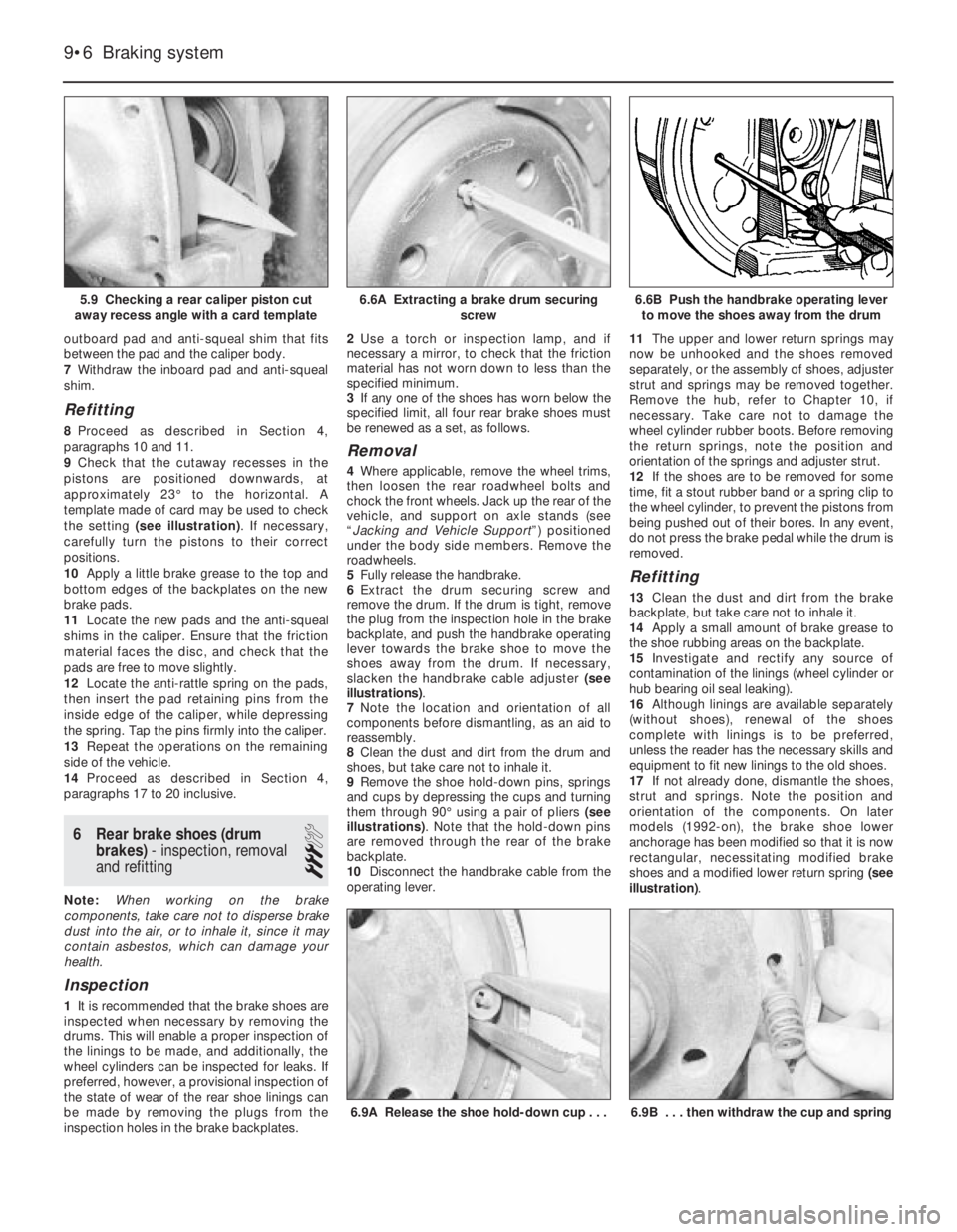
approximately 23°to the horizontal. A
template made of card may be used to check
the setting (see illustration). If necessary,
carefully turn the pistons to their correct
positions.
10Apply a little brake grease to the top and
bottom edges of the backplates on the new
brake pads.
11Locate the new pads and the anti-squeal
shims in the caliper. Ensure that the friction
material faces the disc, and check that the
pads are free to move slightly.
12Locate the anti-rattle spring on the pads,
then insert the pad retaining pins from the
inside edge of the caliper, while depressing
the spring. Tap the pins firmly into the caliper.
13Repeat the operations on the remaining
side of the vehicle.
14Proceed as described in Section 4,
paragraphs 17 to 20 inclusive.
6Rear brake shoes (drum
brakes) - inspection, removal
and refitting
3
Note: When working on the brake
components, take care not to disperse brake
dust into the air, or to inhale it, since it may
contain asbestos, which can damage your
health.
Inspection
1It is recommended that the brake shoes are
inspected when necessary by removing the
drums. This will enable a proper inspection of
the linings to be made, and additionally, the
wheel cylinders can be inspected for leaks. If
preferred, however, a provisional inspection of
the state of wear of the rear shoe linings can
be made by removing the plugs from the
inspection holes in the brake backplates.2Use a torch or inspection lamp, and if
necessary a mirror, to check that the friction
material has not worn down to less than the
specified minimum.
3If any one of the shoes has worn below the
specified limit, all four rear brake shoes must
be renewed as a set, as follows.
Removal
4Where applicable, remove the wheel trims,
then loosen the rear roadwheel bolts and
chock the front wheels. Jack up the rear of the
vehicle, and support on axle stands (see
“Jacking and Vehicle Support”) positioned
under the body side members. Remove the
roadwheels.
5Fully release the handbrake.
6Extract the drum securing screw and
remove the drum. If the drum is tight, remove
the plug from the inspection hole in the brake
backplate, and push the handbrake operating
lever towards the brake shoe to move the
shoes away from the drum. If necessary,
slacken the handbrake cable adjuster (see
illustrations).
7Note the location and orientation of all
components before dismantling, as an aid to
reassembly.
8Clean the dust and dirt from the drum and
shoes, but take care not to inhale it.
9Remove the shoe hold-down pins, springs
and cups by depressing the cups and turning
them through 90°using a pair of pliers (see
illustrations). Note that the hold-down pins
are removed through the rear of the brake
backplate.
10Disconnect the handbrake cable from the
operating lever.11The upper and lower return springs may
now be unhooked and the shoes removed
separately, or the assembly of shoes, adjuster
strut and springs may be removed together.
Remove the hub, refer to Chapter 10, if
necessary. Take care not to damage the
wheel cylinder rubber boots. Before removing
the return springs, note the position and
orientation of the springs and adjuster strut.
12If the shoes are to be removed for some
time, fit a stout rubber band or a spring clip to
the wheel cylinder, to prevent the pistons from
being pushed out of their bores. In any event,
do not press the brake pedal while the drum is
removed.
Refitting
13Clean the dust and dirt from the brake
backplate, but take care not to inhale it.
14Apply a small amount of brake grease to
the shoe rubbing areas on the backplate.
15Investigate and rectify any source of
contamination of the linings (wheel cylinder or
hub bearing oil seal leaking).
16Although linings are available separately
(without shoes), renewal of the shoes
complete with linings is to be preferred,
unless the reader has the necessary skills and
equipment to fit new linings to the old shoes.
17If not already done, dismantle the shoes,
strut and springs. Note the position and
orientation of the components. On later
models (1992-on), the brake shoe lower
anchorage has been modified so that it is now
rectangular, necessitating modified brake
shoes and a modified lower return spring (see
illustration).
9•6Braking system
5.9 Checking a rear caliper piston cut
away recess angle with a card template6.6B Push the handbrake operating lever
to move the shoes away from the drum
6.9B . . . then withdraw the cup and spring6.9A Release the shoe hold-down cup . . .
6.6A Extracting a brake drum securing
screw
Page 138 of 525
18If both brake assemblies are dismantled
at the same time, take care not to mix up the
components. Note that the left-hand and
right-hand adjuster components are marked.
The threaded rod is marked “L” or “R”, and
the other “handed” components are colour-
coded black for the left-hand side, and silver
for the right-hand side.
19Dismantle and clean the adjuster strut.
Apply a smear of silicone-based grease to the
adjuster threads.
20Examine the return springs. If they are
distorted, or if they have seen extensiveservice, renewal is advisable. Weak springs
may cause the brakes to bind.
21If a new handbrake operating lever was
not supplied with the new shoes (where
applicable), transfer the lever from the old
shoes. The lever may be secured with a pin
and circlip, or by a rivet, which will have to be
drilled out.
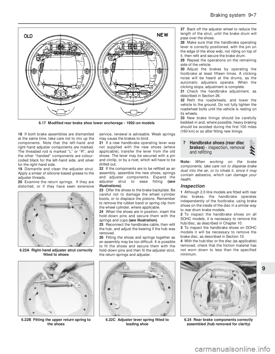
22If the components are to be refitted as an
assembly, assemble the new shoes, springs
and adjuster components. Expand the
adjuster strut to ease fitting (see
illustrations).
23Offer the shoes to the brake backplate. Be
careful not to damage the wheel cylinder
boots, or to displace the pistons. Remember
to remove the rubber band or spring clip from
the wheel cylinder, where applicable.
24When the shoes are in position, insert the
hold-down pins and secure them with the
springs and cups (see illustration).
25Reconnect the handbrake cable, then refit
the hub, and adjust the bearing if the hub was
removed.
26Fitting the shoes and springs together as
an assembly may be too difficult. It is possible
to fit the shoes and secure them with the
hold-down pins and then fit the adjuster strut,
the return springs and adjuster.27Back off the adjuster wheel to reduce the
length of the strut, until the brake drum will
pass over the shoes.
28Make sure that the handbrake operating
lever is correctly positioned, with the pin on
the edge of the shoe web, not riding on top of
it, then refit and secure the brake drum.
29Repeat the operations on the remaining
side of the vehicle.
30Adjust the brakes by operating the
footbrake at least fifteen times. A clicking
noise will be heard at the drums, as the
automatic adjusters operate. When the
clicking stops, adjustment is complete.
31Check the handbrake adjustment, as
described in Section 26.
32Refit the roadwheels, and lower the
vehicle to the ground. Do not fully tighten the
roadwheel bolts until the vehicle is resting on
its wheels.
33New brake linings should be carefully
bedded-in and, where possible, heavy braking
should be avoided during the first 100 miles
(160 km) or so after fitting new linings.
7Handbrake shoes (rear disc
brakes) - inspection, removal
and refitting
3
Note: When working on the brake
components, take care not to disperse brake
dust into the air, or to inhale it, since it may
contain asbestos, which can damage your
health.
Inspection
1Although 2.0 litre models are fitted with rear
disc brakes, the handbrake operates
independently of the footbrake, using brake
shoes on the inside of the disc in a similar way
to rear drum brake models.
2To inspect the handbrake shoes on all
SOHC models, it is necessary to remove the
hub/disc, as described in Chapter 10.
3To inspect the handbrake shoes on DOHC
models it will be necessary to remove the
brake disc, as described in Section 10.
4With the hub/disc or the disc (as applicable)
removed, check that the friction material has
not worn down to less than the specified
minimum.
Braking system 9•7
6.22A Right-hand adjuster strut correctly
fitted to shoes
6.24 Rear brake components correctly
assembled (hub removed for clarity)6.22C Adjuster lever spring fitted to
leading shoe6.22B Fitting the upper return spring to
the shoes
6.17 Modified rear brake shoe lower anchorage - 1992-on models
9
Page 139 of 525
5If any one of the shoes has worn below the
specified limit, all four handbrake shoes must
be renewed as a set, as follows.
SOHC models
Removal
6Clean the dust and dirt from the various
components, but take care not to inhale it.
7Disconnect the handbrake cable and the
return spring from the handbrake operating
lever at the brake backplate. If necessary,
slacken the handbrake cable adjustment, with
reference to Section 26.
8Remove the shoe hold-down pins, springs
and cups by depressing the cups and turning
them through 90°using a pair of pliers. Note
that the hold-down pins are removed through
the rear of the brake backplate.
9The shoes, adjuster, handbrake operating
lever and return springs can now be removed
together as an assembly.
10Note the position and orientation of all
components, then unhook the upper and
lower return springs from the shoes, and
recover the handbrake operating lever and the
adjuster.
Refitting
11Apply a little brake grease to the threads
of the adjuster, then screw it together to its
minimum length. Also apply a little brake
grease to the shoe rubbing areas on the
lockplate.
12Fit one of the new brake shoes, and
secure it to the backplate with the hold-down
pin, spring and cup.
13Fit the handbrake operating lever in
position.
14Fit the remaining brake shoe, and secure
with the hold-down pin, spring and cup.
15Hook the upper return spring onto the
shoes.
16Fit the adjuster between the lower ends of
the shoes, as noted before dismantling, then
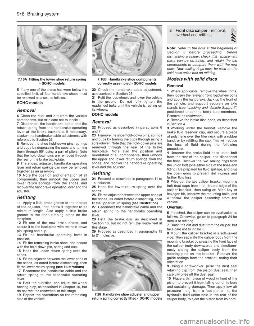
fit the lower return spring (see illustrations).
17Reconnect the handbrake cable and the
return spring to the handbrake operating
lever.
18Refit the hub/disc, and adjust the wheel
bearing play, as described in Chapter 10, but
do not refit the roadwheel at this stage.
19Repeat the operations on the remaining
side of the vehicle.20Check the handbrake cable adjustment,
as described in Section 26.
21Refit the roadwheels and lower the vehicle
to the ground. Do not fully tighten the
roadwheel bolts until the vehicle is resting on
its wheels.
DOHC models
Removal
22Proceed as described in paragraphs 6
and 7.
23Remove the shoe hold-down pins, springs
and cups by turning the cups through using a
screwdriver. Note that the hold-down pins are
removed through the rear of the brake
backplate. Note also the position and
orientation of all components, then unhook
the upper and lower return springs from the
shoes, and recover the handbrake operating
lever and the adjuster.
Refitting
24Proceed as described in paragraphs 11 to
14 inclusive.
25Hook the lower return spring onto the
shoes.
26Fit the adjuster between the upper ends of
the shoes, as noted before dismantling, then
fit the upper return spring (see illustration).
27Reconnect the handbrake cable and the
return spring to the handbrake operating
lever.
28Refit the brake disc as described in
Section 10, but do not refit the roadwheel at
this stage.
29Proceed as described in paragraphs 19
to 21 inclusive.
8Front disc caliper - removal,
overhaul and refitting
3
Note: Refer to the note at the beginning of
Section 3 before proceeding. Before
dismantling a caliper, check that replacement
parts can be obtained, and retain the old
components to compare them with the new
ones. New sealing rings must be used on the
fluid hose union bolt on refitting
Models with solid discs
Removal
1Where applicable, remove the wheel trims,
then loosen the relevant front roadwheel bolts
and apply the handbrake. Jack up the front of
the vehicle, and support securely on axle
stands (see “Jacking and Vehicle Support”)
positioned under the body side members.
Remove the roadwheel.
2Remove the brake disc pads, as described
in Section 4.
3Working under the bonnet, remove the
brake fluid reservoir cap, and secure a piece
of polythene over the filler neck with a rubber
band, or by refitting the cap. This will reduce
the loss of fluid during the following
procedure.
4Unscrew the brake fluid hose union bolt
from the rear of the caliper, and disconnect
the hose. Recover the two sealing rings from
the union bolt (one either side of the hose end
fitting). Be prepared for fluid spillage, and plug
the open ends to prevent dirt ingress and
further fluid loss.
5Prise out the two caliper bracket mounting
bolt dust caps from the inboard edge of the
caliper bracket, then using an Allen key or
hexagon bit, unscrew the mounting bolts, and
withdraw the caliper assembly from the
vehicle.
Overhaul
6If desired, the caliper can be overhauled as
follows. Otherwise, go on to paragraph 24 for
details of refitting.
7Brush the dirt and dust from the caliper, but
take care not to inhale it.
8Mount the caliper bracket in a soft-jawed
vice. Then separate the caliper body from the
mounting bracket by pressing the front face of
the caliper body downwards and simultane-
ously sliding the caliper body from the
locating pins on the bracket. Recover the
guide springs from the bracket, noting their
orientation.
9Using a screwdriver, prise the dust seal
retaining clip from the piston dust seal, then
carefully prise off the dust seal.
10Place a thin piece of wood in front of the
piston to prevent it from falling out of its bore
and sustaining damage. Then apply low air
pressure - e.g. from a foot pump - to the
hydraulic fluid union hole in the rear of the
caliper body, to eject the piston from its bore.
9•8Braking system
7.16A Fitting the lower shoe return spring
- SOHC models
7.26 Handbrake shoe adjuster and upper
return spring correctly fitted - DOHC models
7.16B Handbrake shoe components
correctly assembled - SOHC models
Page 140 of 525
11Remove the wood and carefully withdraw
the piston.
12Carefully prise the seal from the groove in
the caliper piston bore, using a plastic or
wooden instrument.
13Inspect the surfaces of the piston and its
bore in the caliper for scoring, or evidence of
metal-to-metal contact. If evident, renew the
complete caliper assembly.
14If the piston and bore are in good
condition, discard the seals and obtain a
repair kit, which will contain all the necessary
renewable items.
15Clean the piston and cylinder bore with
brake fluid or methylated spirit, nothing else!
16Begin reassembly by fitting the seal into
the caliper bore.
17Locate the dust seal in its groove in the
piston. Dip the piston in clean brake fluid and
insert it squarely into the cylinder. Check that
the cutaway recesses in the piston are
positioned horizontally. If necessary, carefully
turn the piston to its correct position.
18When the piston has been partially
depressed, engage the dust seal with the rim
of the caliper bore, and fit the retaining clip.
19Push the piston further into its bore, but
not as far as the stop, ensuring that it does
not jam.
20If desired, the caliper body locating pin
rubbers can be renewed. Extract the nylon
compression sleeve from within each rubber,
then carefully compress the rubber shoulder,
and push the rubber through the hole in the
caliper body to remove it from the inboard
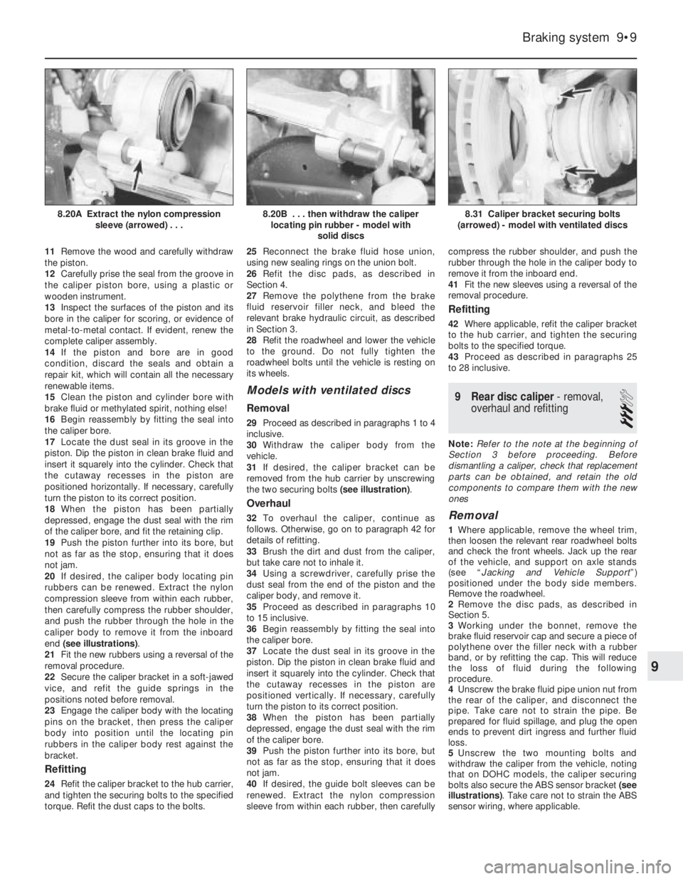
end (see illustrations).
21Fit the new rubbers using a reversal of the
removal procedure.
22Secure the caliper bracket in a soft-jawed
vice, and refit the guide springs in the
positions noted before removal.
23Engage the caliper body with the locating
pins on the bracket, then press the caliper
body into position until the locating pin
rubbers in the caliper body rest against the
bracket.
Refitting
24Refit the caliper bracket to the hub carrier,
and tighten the securing bolts to the specified
torque. Refit the dust caps to the bolts.25Reconnect the brake fluid hose union,
using new sealing rings on the union bolt.
26Refit the disc pads, as described in
Section 4.
27Remove the polythene from the brake
fluid reservoir filler neck, and bleed the
relevant brake hydraulic circuit, as described
in Section 3.
28Refit the roadwheel and lower the vehicle
to the ground. Do not fully tighten the
roadwheel bolts until the vehicle is resting on
its wheels.
Models with ventilated discs
Removal
29Proceed as described in paragraphs 1 to 4
inclusive.
30Withdraw the caliper body from the
vehicle.
31If desired, the caliper bracket can be
removed from the hub carrier by unscrewing
the two securing bolts (see illustration).
Overhaul
32To overhaul the caliper, continue as
follows. Otherwise, go on to paragraph 42 for
details of refitting.
33Brush the dirt and dust from the caliper,
but take care not to inhale it.
34Using a screwdriver, carefully prise the
dust seal from the end of the piston and the
caliper body, and remove it.
35Proceed as described in paragraphs 10
to 15 inclusive.
36Begin reassembly by fitting the seal into
the caliper bore.
37Locate the dust seal in its groove in the
piston. Dip the piston in clean brake fluid and
insert it squarely into the cylinder. Check that
the cutaway recesses in the piston are
positioned vertically. If necessary, carefully
turn the piston to its correct position.
38When the piston has been partially
depressed, engage the dust seal with the rim
of the caliper bore.
39Push the piston further into its bore, but
not as far as the stop, ensuring that it does
not jam.
40If desired, the guide bolt sleeves can be
renewed. Extract the nylon compression
sleeve from within each rubber, then carefullycompress the rubber shoulder, and push the
rubber through the hole in the caliper body to
remove it from the inboard end.
41Fit the new sleeves using a reversal of the
removal procedure.
Refitting
42Where applicable, refit the caliper bracket
to the hub carrier, and tighten the securing
bolts to the specified torque.
43Proceed as described in paragraphs 25
to 28 inclusive.
9Rear disc caliper - removal,
overhaul and refitting
3
Note: Refer to the note at the beginning of
Section 3 before proceeding. Before
dismantling a caliper, check that replacement
parts can be obtained, and retain the old
components to compare them with the new
ones
Removal
1Where applicable, remove the wheel trim,
then loosen the relevant rear roadwheel bolts
and check the front wheels. Jack up the rear
of the vehicle, and support on axle stands
(see “Jacking and Vehicle Support”)
positioned under the body side members.
Remove the roadwheel.
2Remove the disc pads, as described in
Section 5.
3Working under the bonnet, remove the
brake fluid reservoir cap and secure a piece of
polythene over the filler neck with a rubber
band, or by refitting the cap. This will reduce
the loss of fluid during the following
procedure.
4Unscrew the brake fluid pipe union nut from
the rear of the caliper, and disconnect the
pipe. Take care not to strain the pipe. Be
prepared for fluid spillage, and plug the open
ends to prevent dirt ingress and further fluid
loss.
5Unscrew the two mounting bolts and
withdraw the caliper from the vehicle, noting
that on DOHC models, the caliper securing
bolts also secure the ABS sensor bracket (see
illustrations). Take care not to strain the ABS
sensor wiring, where applicable.
Braking system 9•9
8.31 Caliper bracket securing bolts
(arrowed) - model with ventilated discs8.20B . . . then withdraw the caliper
locating pin rubber - model with
solid discs8.20A Extract the nylon compression
sleeve (arrowed) . . .
9
Page 141 of 525
Overhaul
6If desired, the caliper can be overhauled as
follows. Otherwise, go on to paragraph 20 for
details of refitting.
7Brush the dirt and dust from the caliper, but
take care not to inhale it.
8Note that no attempt must be made to
separate the two halves of the caliper.
9Using a screwdriver, prise the dust seal
retaining clips from the piston dust seals, then
carefully prise off the dust seals.
10Using a clamp, secure one of the pistons
in its fully retracted position. Then apply low
air pressure (e.g. from a foot pump), to the
hydraulic fluid union hole in the rear of the
caliper body, to eject the remaining piston
from its bore. Take care not to drop the
piston, which may result in damage.
11Temporarily close off the bore of the
removed piston, using a flat piece of wood or
similar improvised tool. Then remove the
clamp from the remaining piston, and again
apply air pressure to the caliper union to eject
the piston.
12Carefully prise the seals from the grooves
in the caliper piston bores, using a plastic or
wooden instrument.
13Inspect the surfaces of the pistons and
their bores in the caliper for scoring, or
evidence of metal-to-metal contact. If evident,
renew the complete caliper assembly.
14If the pistons and bores are in good
condition, discard the seals and obtain a
repair kit, which will contain all the necessary
renewable items. Also obtain a tube of brake
cylinder paste.
15Clean the piston and cylinder bore with
brake fluid or methylated spirit - nothing else!
16Apply a little brake cylinder paste to the
pistons, cylinder bores and piston seals.
17Begin reassembly by fitting the seals to
the grooves in the caliper bores.
18Locate the dust seals in their grooves in
the pistons, then insert the pistons carefully
into their bores until they enter the seals. It
may be necessary to rotate the pistons to
prevent them from jamming in the seals.
19When the pistons have been partially
depressed, engage the dust seals with the
rims of the caliper bores, and fit the retaining
clips.
Refitting
20Refit the caliper and tighten the securing
bolts to the specified torque, ensuring that the
ABS sensor bracket is in position, where
applicable.
21Reconnect the brake fluid pipe to the
caliper, and tighten the union nut.
22Refit the disc pads, as described in
Section 5.
23Remove the polythene from the brake
fluid reservoir filler neck and bleed the
relevant brake hydraulic circuit, as described
in Section 3.
24Refit the roadwheel and lower the vehicle
to the ground. Do not fully tighten the
roadwheel bolts until the vehicle is resting on
its wheels.
10Brake disc - inspection,
removal and refitting
3
Inspection
1Where applicable, remove the wheel trim,
then loosen the relevant roadwheel bolts. If
checking a front disc, apply the handbrake,
and if checking a rear disc, chock the front
wheels, then jack up the relevant end of the
vehicle and support on axle stands (see
“Jacking and Vehicle Support”) positioned
under the body side members. Remove the
roadwheel.
2Where applicable, check that the brake disc
securing screw is tight. Then fit a spacer
approximately 10.0 mm (0.4 in) thick to one of
the roadwheel bolts, and refit and tighten the
bolt in the hole opposite the disc securing
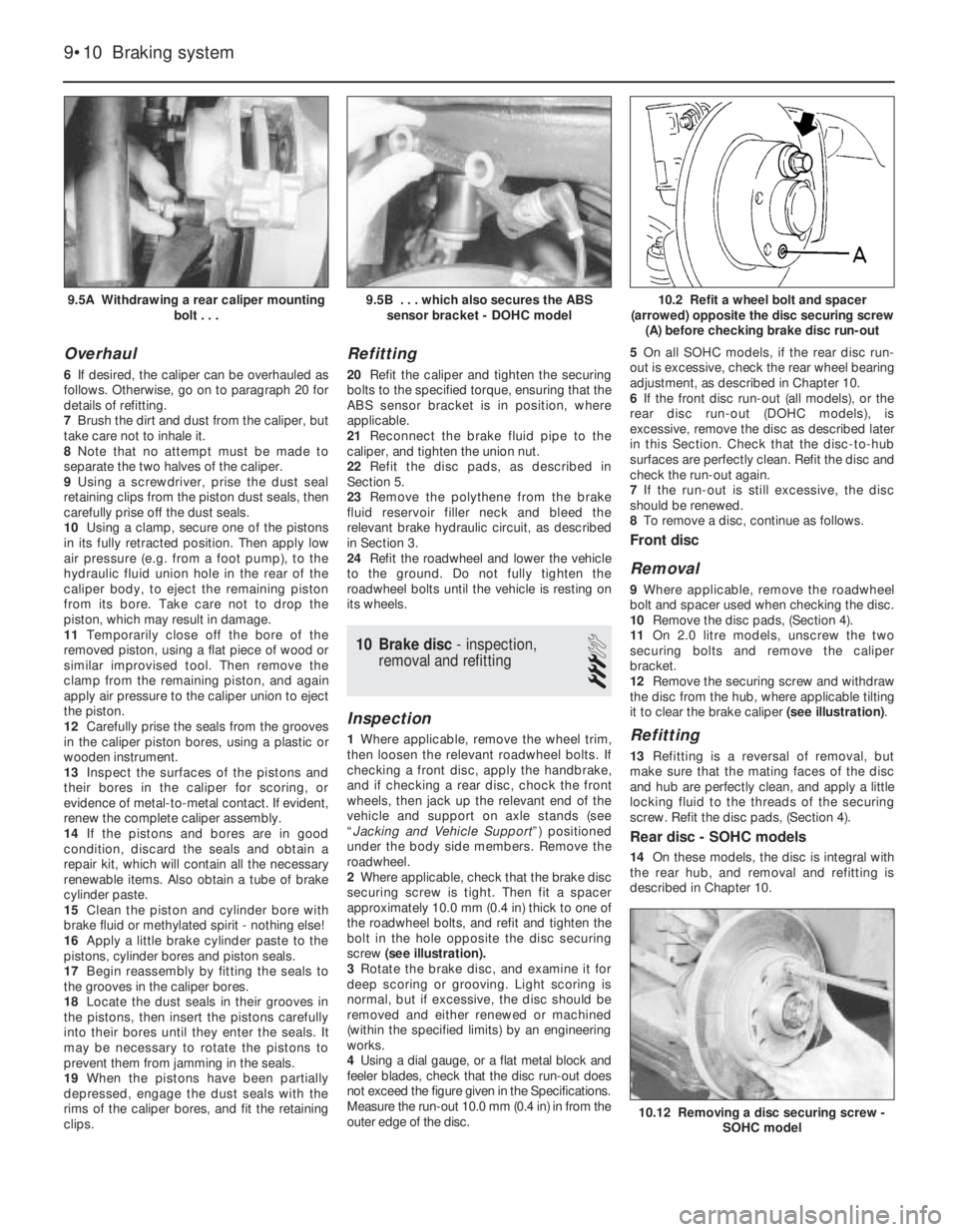
screw (see illustration).
3Rotate the brake disc, and examine it for
deep scoring or grooving. Light scoring is
normal, but if excessive, the disc should be
removed and either renewed or machined
(within the specified limits) by an engineering
works.
4Using a dial gauge, or a flat metal block and
feeler blades, check that the disc run-out does
not exceed the figure given in the Specifications.
Measure the run-out 10.0 mm (0.4 in) in from the
outer edge of the disc. 5On all SOHC models, if the rear disc run-
out is excessive, check the rear wheel bearing
adjustment, as described in Chapter 10.
6If the front disc run-out (all models), or the
rear disc run-out (DOHC models), is
excessive, remove the disc as described later
in this Section. Check that the disc-to-hub
surfaces are perfectly clean. Refit the disc and
check the run-out again.
7If the run-out is still excessive, the disc
should be renewed.
8To remove a disc, continue as follows.
Front disc
Removal
9Where applicable, remove the roadwheel
bolt and spacer used when checking the disc.
10Remove the disc pads, (Section 4).
11On 2.0 litre models, unscrew the two
securing bolts and remove the caliper
bracket.
12Remove the securing screw and withdraw
the disc from the hub, where applicable tilting
it to clear the brake caliper (see illustration).
Refitting
13Refitting is a reversal of removal, but
make sure that the mating faces of the disc
and hub are perfectly clean, and apply a little
locking fluid to the threads of the securing
screw. Refit the disc pads, (Section 4).
Rear disc - SOHC models
14On these models, the disc is integral with
the rear hub, and removal and refitting is
described in Chapter 10.
9•10Braking system
9.5A Withdrawing a rear caliper mounting
bolt . . .10.2 Refit a wheel bolt and spacer
(arrowed) opposite the disc securing screw
(A) before checking brake disc run-out
10.12 Removing a disc securing screw -
SOHC model
9.5B . . . which also secures the ABS
sensor bracket - DOHC model
Page 142 of 525
Rear disc - DOHC models
Removal
15Where applicable, remove the roadwheel
bolt and spacer used when checking the disc.
16Remove the disc pads, as described in
Section 5.
17Remove the brake caliper with reference
to Section 9, but leave the hydraulic fluid pipe
connected. Move the caliper to one side, and
suspend it using wire or string to avoid
straining the pipe.
18Remove the securing screw and withdraw
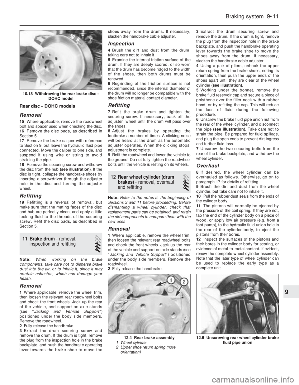
the disc from the hub (see illustration). If the
disc is tight, collapse the handbrake shoes by
inserting a screwdriver through the adjuster
hole in the disc and turning the adjuster
wheel.
Refitting
19Refitting is a reversal of removal, but
make sure that the mating faces of the disc
and hub are perfectly clean, and apply a little
locking fluid to the threads of the securing
screw. Refit the disc pads, as described in
Section 5.
11Brake drum - removal,
inspection and refitting
3
Note: When working on the brake
components, take care not to disperse brake
dust into the air, or to inhale it, since it may
contain asbestos, which can damage your
health.
Removal
1Where applicable, remove the wheel trim,
then loosen the relevant rear roadwheel bolts
and chock the front wheels. Jack up the rear
of the vehicle, and support on axle stands
(see “Jacking and Vehicle Support”)
positioned under the body side members.
Remove the roadwheel.
2Fully release the handbrake.
3Extract the drum securing screw and
remove the drum. If the drum is tight, remove
the plug from the inspection hole in the brake
backplate, and push the handbrake operating
lever towards the brake shoe to move theshoes away from the drums. If necessary,
slacken the handbrake cable adjuster.
Inspection
4Brush the dirt and dust from the drum,
taking care not to inhale it.
5Examine the internal friction surface of the
drum. If they are deeply scored, or so worn
that the drum has become ridged to the width
of the shoes, then both drums must be
renewed.
6Regrinding of the friction surface is not
recommended, since the internal diameter of
the drum will no longer be compatible with the
shoe friction material contact diameter.
Refitting
7Refit the brake drum and tighten the
securing screw. If necessary, back off the
adjuster wheel until the drum will pass over
the shoes.
8Adjust the brakes by operating the
footbrake a number of times. A clicking noise
will be heard at the drum as the automatic
adjuster operates. When the clicking stops,
adjustment is complete.
9Refit the roadwheel and lower the vehicle to
the ground. Do not fully tighten the roadwheel
bolts until the vehicle is resting on its wheels.
12Rear wheel cylinder (drum
brakes) - removal, overhaul
and refitting
3
Note: Refer to the notes at the beginning of
Sections 3 and 11 before proceeding. Before
dismantling a wheel cylinder, check that
replacement parts can be obtained, and retain
the old components to compare them with the
new ones
Removal
1Where applicable, remove the wheel trim,
then loosen the relevant rear roadwheel bolts
and chock the front wheels. Jack up the rear
of the vehicle and support on axle stands (see
“Jacking and Vehicle Support”) positioned
under the body side members. Remove the
roadwheel.
2Fully release the handbrake.3Extract the drum securing screw and
remove the drum. If the drum is tight, remove
the plug from the inspection hole in the brake
backplate, and push the handbrake operating
lever towards the brake shoe to move the
shoes away from the drum. If necessary,
slacken the handbrake cable adjuster.
4Using a pair of pliers, unhook the upper
return spring from the brake shoes, noting its
orientation, then push the upper ends of the
shoes apart until they are clear of the wheel
cylinder (see illustration).
5Working under the bonnet, remove the
brake fluid reservoir cap and secure a piece of
polythene over the filler neck with a rubber
band, or by refitting the cap. This will reduce
the loss of fluid during the following
procedure.
6Unscrew the brake fluid pipe union nut from
the rear of the wheel cylinder, and disconnect
the pipe (see illustration). Take care not to
strain the pipe. Be prepared for fluid spillage,
and plug the open ends to prevent dirt ingress
and further fluid loss.
7Unscrew the two securing bolts from the
rear of the brake backplate, and withdraw the
wheel cylinder.
Overhaul
8If desired, the wheel cylinder can be
overhauled as follows. Otherwise, go on to
paragraph 17 for details of refitting.
9Brush the dirt and dust from the wheel
cylinder, but take care not to inhale it.
10Pull the rubber dust seals from the ends of
the cylinder body.
11The pistons will normally be ejected by
the pressure of the coil spring. If they are not,
tap the end of the cylinder body on a piece of
wood, or apply low air pressure (e.g. from a
foot pump), to the hydraulic fluid union hole in
the rear of the cylinder body, to eject the
pistons from their bores.
12Inspect the surfaces of the pistons and
their bores in the cylinder body for scoring, or
evidence of metal-to-metal contact. If evident,
renew the complete wheel cylinder assembly.
Note that the later type of wheel cylinder can
be used to replace the early type as a
complete unit.
Braking system 9•11
12.6 Unscrewing rear wheel cylinder brake
fluid pipe union12.4 Rear brake assembly
1 Wheel cylinder
2 Upper shoe return spring (note
orientation)
10.18 Withdrawing the rear brake disc -
DOHC model
9