1988 JEEP CHEROKEE seat adjustment
[x] Cancel search: seat adjustmentPage 317 of 1378

and reinstalled. Brake shoes can be manually adjusted by rotating
adjuster screw. Remove access slot cover.
3) Using a small blade screwdriver, push in on adjustment
lever to separate from adjustment screw. Turn adjustment screw until
brake drum is locked tight. Back screw off until wheel rotates freely.
If brake drum is to be removed, back off adjustment screw several
notches for adequate clearance.
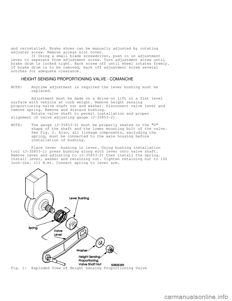
HEIGHT SENSING PROPORTIONING VALVE - COMANCHE
NOTE: Anytime adjustment is required the lever bushing must be
replaced.
Adjustment must be made on a drive-on lift or a flat level
surface with vehicle at curb weight. Remove height sensing
proportioning valve shaft nut and washer. Disconnect valve lever and
remove spring. Remove and discard bushing.
Rotate valve shaft to permit installation and proper
alignment of valve adjusting gauge (J-35853-2).
NOTE: The gauge (J-35853-2) must be properly seated on the "D"
shape of the shaft and the lower mounting bolt of the valve.
See Fig. 2. Also, all linkage components, excluding the
spring, must be connected to the axle housing before
installation of bushing.
Place lever bushing in lever. Using bushing installation
tool (J-35853-1) press bushing along with lever onto valve shaft.
Remove lever and adjusting to (J-35853-2) then install the spring.
Install lever, washer and retaining nut. Tighten retaining nut to 100
Inch-lbs. (11 N.m). Connect spring to lever arm.
Fig. 1: Exploded View of Height Sensing Proportioning Valve
Page 365 of 1378

Plate (J 23781-7) in bottom side gear. Install grease in centering
hole of step plate. Position Rotating Tool (J 23781-3) on step plate
tool. Coat threads of Forcing Screw (J 8646-2) with oil.
2) Insert forcing Screw (J 8646-2) through case and thread
into rotating tool. Thread screw through tool until it contacts
centering hole in step plate. Tighten forcing screw to relieve clutch
pack tension from pinions. Remove pinion thrust washers.
3) Tighten forcing screw until all clutch pack tension is
relieved from pinions. Slide rotating tool pawl so it engages with
side gear teeth. Rotate side gears with rotating tool until pinions
can be removed through case opening.
4) Remove forcing screw, rotating tool, upper side gear and
clutch pack. Remove differential case from axle shaft. Remove
remaining side gear, clutch pack and step plate tool. Remove retainer
clips from clutch packs. Mark clutch packs for reassembly reference.
Using a press, remove differential bearings.
Cleaning & Inspection
Clean all parts and dry with compressed air. If any clutch
plates or discs require replacement, all plates and discs should be
replaced. Replace any worn or damaged components.
NOTE: For adjustment procedures, see DANA SEMI-FLOATING or
FULL FLOATING AXLE articles in this section
Reassembly
1) Lightly lubricate clutch pack discs with axle lubricant.
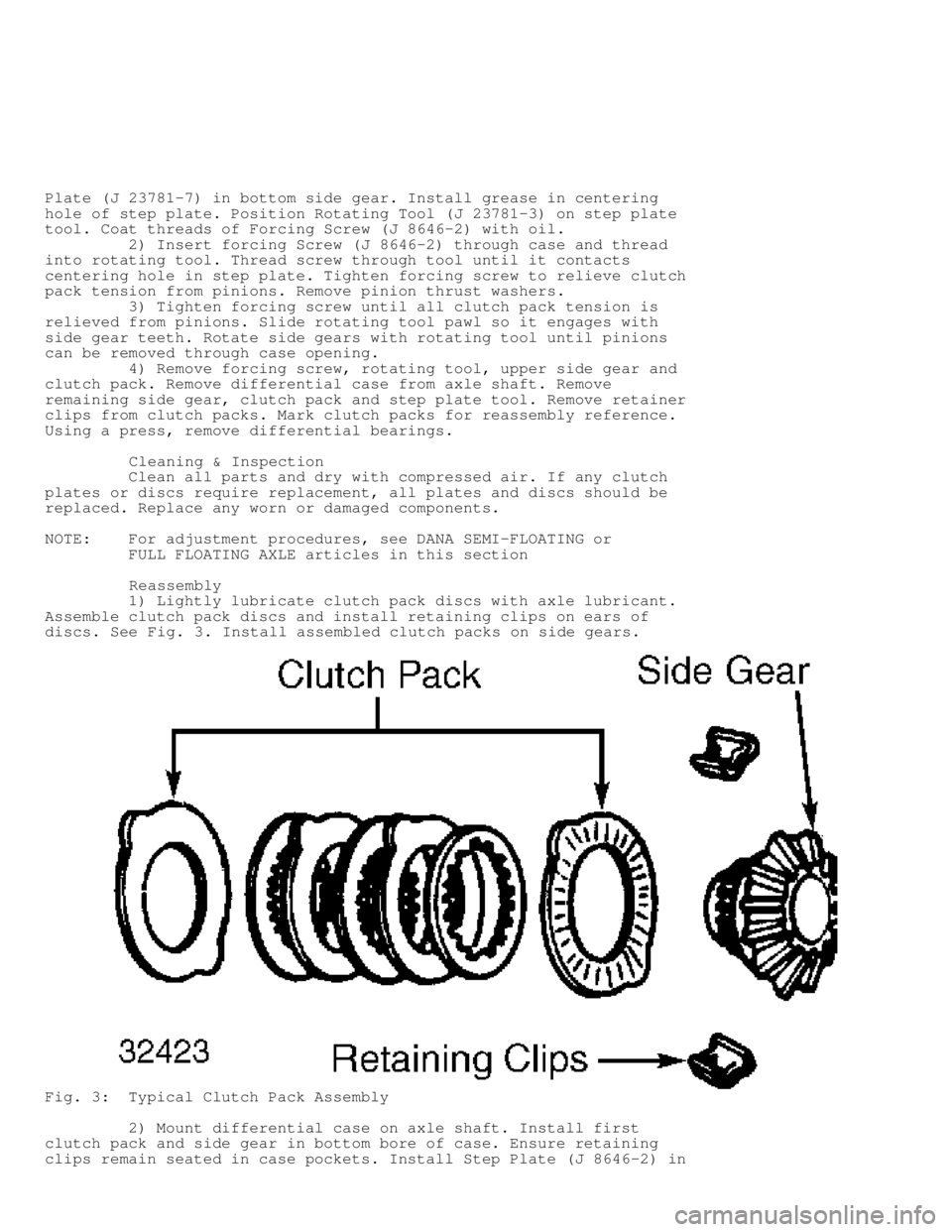
Assemble clutch pack discs and install retaining clips on ears of
discs. See Fig. 3. Install assembled clutch packs on side gears.
Fig. 3: Typical Clutch Pack Assembly
2) Mount differential case on axle shaft. Install first
clutch pack and side gear in bottom bore of case. Ensure retaining
clips remain seated in case pockets. Install Step Plate (J 8646-2) in
Page 396 of 1378

size end play shims on each side of differential case. Position and
install ring gear on differential case. Install replacement ring gear
bolts and tighten standard axle ring gear bolts to 70-90 ft. lbs.
(95-122 N.m). Tighten heavy duty drive axle bolts to 105 ft. lbs.
(142 N.m).
4) Check ring gear backlash. See RING GEAR BACKLASH in
ADJUSTMENTS. Lightly lubricate differential bearings, cups, gears and
thrust washers with axle lubricant. Install bearing cups on
differential bearings. Install differential in axle housing.
5) Using a soft faced hammer, tap outer edges of differential
bearing cups to seat them in housing. Install differential bearings
caps and tighten cap bolts to 57 ft. lbs. (77 N.m).
6) Recheck and verify ring gear backlash has not changed.
Install axle housing cover. Tighten cover bolts to 14 ft. lbs. (19 N.
m). Refill axle with 75-90W gear lubricant.
ADJUSTMENTS
DRIVE PINION DEPTH
1) Check numbers painted on drive pinion and ring gear. First
number on pinion must match number on ring gear. Second number on
pinion is pinion depth variance. If number is preceded by a plus sign,
add that number to standard pinion depth. If number is preceded by a
minus sign, subtract that amount from standard pinion depth. This will
give desired pinion depth. Record this measurement for future
reference.
2) If numbers painted on drive gear and ring gear do not
match, gears are not a matched set and should not be used. Some
factory installed sets may have .01" (.25 mm) or .02" (.50 mm)
machined off pinion end face.
3) Identifying numbers will appear as "+23". Number "2"
indicates .02" (.50 mm) was removed from end face and number "3" is
pinion depth variance. If marked "+16", number "1" indicates .010"
(.25 mm) was removed from end face and number "6" is pinion depth
variance.
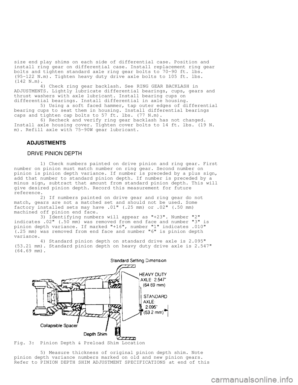
4) Standard pinion depth on standard drive axle is 2.095"
(53.21 mm). Standard pinion depth on heavy duty drive axle is 2.547"
(64.69 mm).
Fig. 3: Pinion Depth & Preload Shim Location
5) Measure thickness of original pinion depth shim. Note
pinion depth variance numbers marked on old and new pinion gears.
Refer to PINION DEPTH SHIM ADJUSTMENT SPECIFICATIONS at end of this
Page 400 of 1378

using shims selected to remove end play. Tighten bearing cap bolts
evenly to 57 ft. lbs. (77 N.m) for standard drive axle and 85 ft. lbs.\
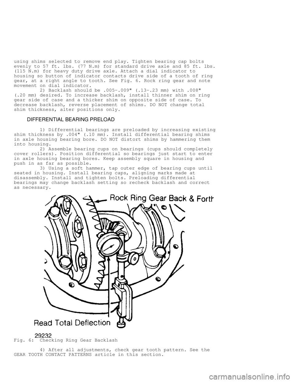
(115 N.m) for heavy duty drive axle. Attach a dial indicator to
housing so button of indicator contacts drive side of a tooth of ring
gear, at a right angle to tooth. See Fig. 6. Rock ring gear and note
movement on dial indicator.
2) Backlash should be .005-.009" (.13-.23 mm) with .008"
(.20 mm) desired. To increase backlash, install thinner shim on ring
gear side of case and a thicker shim on opposite side of case. To
decrease backlash, reverse placement of shims. DO NOT change total
shim thickness, alter positions only.
DIFFERENTIAL BEARING PRELOAD
1) Differential bearings are preloaded by increasing existing
shim thickness by .004" (.10 mm). Install differential bearing shims
in axle housing bearing bore. DO NOT distort shims by hammering them
into housing.
2) Assemble bearing cups on bearings (cups should completely
cover rollers). Position differential so bearings just start to enter
in axle housing bearing bores. Keep assembly square in housing and
push in as far as possible.
3) Using a soft hammer, tap outer edge of bearing cups until
seated in housing. Install bearing caps, aligning marks made at
disassembly. Install and tighten bolts. Preloading differential
bearings may change backlash setting so recheck backlash and correct
as necessary.
Fig. 6: Checking Ring Gear Backlash
4) After all adjustments, check gear tooth pattern. See the
GEAR TOOTH CONTACT PATTERNS article in this section.
Page 613 of 1378

Install head bolts. Head bolts should be tightened in proper
steps and sequence to specification. See Fig. 1. Install remaining
components. Tighten all bolts to specification. Adjust valves if
required. See VALVE ADJUSTMENT in this article.
NOTE: Some manufacturers require that head bolts be retightened
after specified amount of operation. This must be done to
prevent head gasket failure.
VALVE ADJUSTMENT
Engine specifications will indicate valve train clearance and
temperature at which adjustment is to be made on most models. In most
cases, adjustment will be made with a cold engine. In some cases, both
a cold and a hot clearance will be given for maintenance convenience.
On some models, adjustment is not required. Rocker arms are
tightened to specification and valve lash is automatically set. On
some models with push rod actuated valve train, adjustment is made at
push rod end of rocker arm while other models do not require
adjustment.
Clearance will be checked between tip of rocker arm and tip
of valve stem in proper sequence using a feeler gauge. Adjustment is
made by rotating adjusting screw until proper clearance is obtained.
Lock nut is then tightened. Engine will be rotated to obtain all valve
adjustments to manufacturer's specifications.
Some models require hydraulic lifter to be bled down and
clearance measured. Different length push rods can be used to obtain
proper clearance. Clearance will be checked between tip of rocker arm
and tip of valve stem in proper sequence using a feeler gauge.
On overhead cam engines designed without rocker arms actuate
valves directly on a cam follower. A hardened, removable disc is
installed between the cam lobe and lifter. Clearance will be checked
between cam heel and adjusting disc in proper sequence using a feeler
gauge. Engine will be rotated to obtain all valve adjustments.
On overhead cam engines designed with rocker arms, adjustment
is made at push rod end of rocker arm. Ensure that the valve to be
adjusted is riding on the heel of the cam on all engines. Clearance
will be checked between tip of rocker arm and tip of valve stem in
proper sequence using a feeler gauge. Adjustment is made by rotating
adjusting screw until proper clearance is obtained. Lock nut is then
tightened. Engine will be rotated to obtain all valve adjustments to
manufacturer's specifications.
CYLINDER HEAD OVERHAUL
* PLEASE READ THIS FIRST *
NOTE: Always refer to appropriate engine overhaul article in the
ENGINES section for complete overhaul procedures and
specifications for the vehicle being repaired.
DISASSEMBLY
Mark valves for location. Using valve spring compressor,
compress valve springs. Remove valve locks. Carefully release spring
compressor. Remove retainer or rotator, valve spring, spring seat and
valve. See Fig. 2.
Page 623 of 1378

ROCKER ARMS & ASSEMBLIES
Rocker Studs
Rocker studs are either threaded or pressed in place.
Threaded studs are removed by locking 2 nuts on the stud. Unscrew the
stud by turning the jam nut. Coat the stud threads with Loctite and
install. Tighten to specification.
Pressed in stud can be removed using a stud puller. Ream the
stud bore to proper specification and press in a new oversize stud.
Pressed in studs are often replaced by cutting threads in the stud
bore to accept a threaded stud.
Rocker Arms & Shafts
Mark rocker arms for location. Remove rocker arm retaining
bolts. Remove rocker arms. Inspect rocker arms, shafts, bushings and
pivot balls (if equipped) for excessive wear. Inspect rocker arms
for wear in valve stem contact area. Measure rocker arm bushing I.D.
Replace bushings if excessively worn.
The rocker arm valve stem contact point can be reground,
using special fixture for valve grinding machine. Remove minimum
amount of material as possible. Ensure all oil passages are clear.
Install rocker arms in original locations. Ensure rocker arm is
properly seated in push rod. Tighten bolts to specification. Adjust
valves if required. See VALVE ADJUSTMENT in this article.
Pushrods
Remove rocker arms. Mark push rods for location. Remove push
rods. Push rods can be steel or aluminum, solid or hollow. Hollow
pushrods must be internally cleaned to ensure oil passage to the
rocker arms is cleaned. Check the pushrod for damage, such as loose
ends on steel tipped aluminum types.
Check push rod for straightness. Roll push rod on a flat
surface. Using feeler gauge, check clearance at center. Replace push
rod if bent. The push rod can also be supported at each end and
rotated. A dial indicator is used to detect bends in the push rod.
Lubricate ends of push rod and install push rod in original
location. Ensure push rod is properly seated in lifter. Install rocker
arm. Tighten bolts to specification. Adjust valves if required. See
VALVE ADJUSTMENT in this article.
LIFTERS
Hydraulic Lifters
Before replacing a hydraulic lifter for noisy operation,
ensure noise is not caused by worn rocker arms or valve tips.
Hydraulic lifter assemblies must be installed in original locations.
Remove the rocker arm assembly and push rod. Mark components for
location. Some applications require intake manifold, or lifter cover
removal. Remove lifter retainer plate (if used). To remove lifters,
use a hydraulic lifter remover or magnet. Different type lifters are
used. See Fig. 13.
Page 648 of 1378

Engine pre-oiling can be done using pressure oiler (if
available). Connect pressure oiler to cylinder block oil passage
such as oil pressure sending unit. Operate pressure oiler long enough
to ensure correct amount of oil has filled crankcase. Check oil level
while pre-oiling.
If pressure oiler is not available, disconnect ignition
system. Remove oil pressure sending unit and replace with oil pressure
test gauge. Using starter motor, rotate engine starter until gauge
shows normal oil pressure for several seconds. DO NOT crank engine
for more than 30 seconds to avoid starter motor damage.
Ensure oil pressure has reached the most distant point from
the oil pump. Reinstall oil pressure sending unit. Reconnect ignition
system.
INITIAL START-UP
Start the engine and operate engine at low speed while
checking for coolant, fuel and oil leaks. Stop engine. Recheck coolant
and oil level. Adjust if necessary.
CAMSHAFT
Break-in procedure is required when a new or reground
camshaft has been installed. Operate and maintain engine speed between
1500-2500 RPM for approximately 30 minutes. Procedure may vary due to
manufacturers recommendations.
PISTON RINGS
Piston rings require a break-in procedure to ensure seating
of rings to cylinder walls. Serious damage may occur to rings if
correct procedures are not followed.
Extremely high piston ring temperatures are produced obtained
during break-in process. If rings are exposed to excessively high RPM
or high cylinder pressures, ring damage can occur. Follow piston ring
manufacturer's recommended break-in procedure.
FINAL ADJUSTMENTS
Check or adjust ignition timing and dwell (if applicable).
Adjust valves (if necessary). Adjust carburetion or injection idle
speed and mixture. Retighten cylinder heads (if required). If
cylinder head or block is aluminum, retighten bolts when engine is
cold. Follow the engine manufacturer's recommended break-in procedure
and maintenance schedule for new engines.
NOTE: Some manufacturer's require that head bolts be retightened
after specified amount of operation. This must be done to
prevent head gasket failure.
Page 771 of 1378

Roll-Over Check Valve
When valve is inverted, a stainless steel ball pushes a
plunger against its seat, blocking fuel flow through valve.
Charcoal Canister
All models are equipped with a dual-purge type canister. An
inlet is provided for carburetor fuel bowl vapors and another one for
fuel tank vapors. The outlet is connected to intake manifold vacuum.
A secondary purge fourth nipple connects to carburetor ported vacuum.
During engine operation, manifold vacuum draws fresh air
through inlet filter in bottom of canister and purges stored vapors.
When ported vacuum reaches 12 in. Hg, secondary purge circuit is
opened and canister purges at a much higher rate.
Carburetor Bowl Vent
The carburetor bowl vent provides an outlet for fuel vapors
when engine is not operating. During engine operation, fuel bowl is
vented to inside of air cleaner. The bowl is automatically closed by
mechanical link to throttle when engine is started.
MAINTENANCE
No adjustments are required with this system. Replace air
inlet filter (if equipped) in bottom of charcoal canister every
30,000 miles. Regular inspection should be made and defective
components replaced as necessary.