Page 799 of 1378

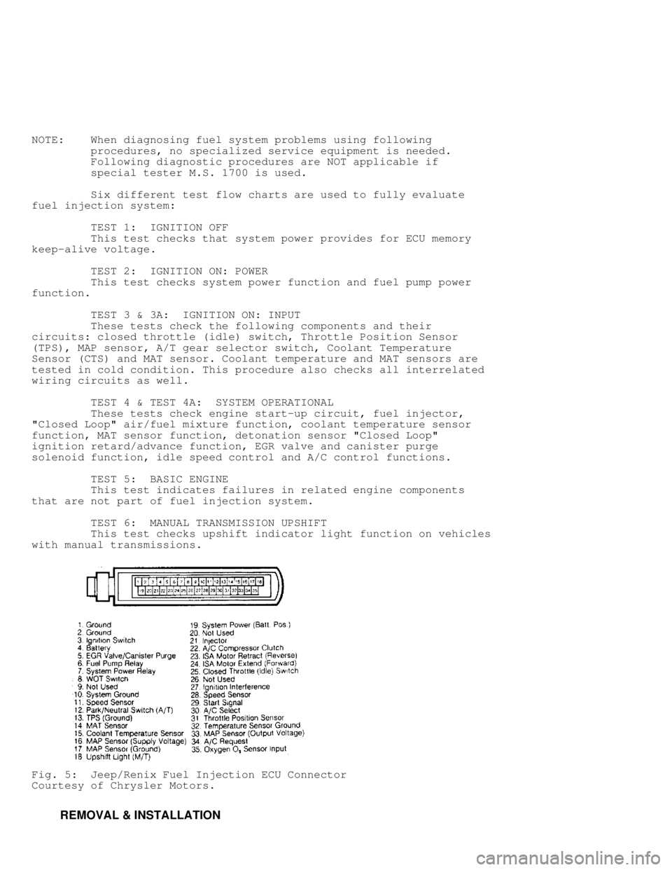
2) Test resistance in wiring harness between ECU harn
terminal No. 32 and sensor connector terminal. Also test resistance
in wiring harness between ECU harness terminal No. 15 and sensor
connector terminal. See Fig. 5. Repair wiring harness if open circuit
or resistance greater than one ohm is indicated.
TEMPERATURE-TO-RESISTANCE VALUES (CTS & MAT SENSOR) TABLE
������������������\
������������������\
������������������\
������������������\
������������������\
������������������\
������������������\
��� �
F �C Ohms
(Approximate)
212 ......................... 100 ........................... 185
160 ......................... 70 ............................ 450
100 ......................... 38 ........................... 1600
70 .......................... 20 ........................... 3400
40 ........................... 4 ........................... 7500
20 .......................... -7 ......................... 13,500
0 ........................... -18 ........................ 25,000
-40 ......................... -40 ....................... 100,700
������������������\
������������������\
������������������\
������������������\
������������������\
������������������\
������������������\
���
Throttle Position Sensor (TPS) Test
Turn ignition on. Check voltage at terminal connector
without disconnecting from TPS. Terminal "A" (M/T), or terminal "B"
(A/T ) is output voltage, which should be 4.6-4.7 volts at wide open
throttle (M/T), or .2 volt at closed throttle (A/T). Terminal "B"
(M/T), or terminal "A" (A/T) is sensor ground. Terminal "C" (M/T),\
or
terminal "D" (A/T) is input voltage, which is about 5 volts.
Closed Throttle (Idle) Switch Test
NOTE: ALL testing of idle switch must be done with ISA motor
plunger in fully extended position. If switch cannot be
tested without extending plunger, it is possible that ISA
motor has failed. See IDLE SPEED ACTUATOR MOTOR ADJUSTMENT.
1) Turn ignition on. Check idle switch voltage at diagnostic
connector D2, between terminals No. 13 and 7. See Fig. 4. At closed
throttle, voltage should be near zero volts. When switch is off
closed throttle position, voltage reading should be greater than 2
volts.
2) If voltage is always zero, test for short to ground in
harness or switch. Also check for open circuit between switch and
terminal No. 25 of ECU connector. If reading is always greater than 2
volts, check for open circuit in wiring harness between switch
connector and ECU. Also check for open between ground and switch
connector. Replace or repair wiring harness as necessary.
Manifold Absolute Pressure (MAP) Sensor Test
1) Check and repair vacuum hose connections at throttle body
and MAP sensor. Check output voltage at MAP sensor connector terminal
"B" (marked on sensor body) with ignition on, engine off. Voltage
reading should be 4-5 volts. If engine is hot and idling in Neutral,
reading should be 1.5-2.1 volts. Check voltage at terminal No. 33 of
ECU connector. Reading should be same as that at terminal "B" on MAP
sensor connector. See Fig. 4.
2) With ignition on, check MAP sensor supply voltage at
terminal "C". Reading should be 4.5-5.5 volts. Same voltage reading
should be obtained at terminal No. 16 on ECU harness connector. If
necessary, repair or replace wiring harness. Using Diagnostic Tester
(MS 1700), test ECU if necessary. Check MAP sensor ground circuit at
terminal "A" and terminal No. 17 of ECU connector. Repair wiring if
necessary.
Page 801 of 1378

NOTE: When diagnosing fuel system problems using following
procedures, no specialized service equipment is needed.
Following diagnostic procedures are NOT applicable if
special tester M.S. 1700 is used.
Six different test flow charts are used to fully evaluate
fuel injection system:
TEST 1: IGNITION OFF
This test checks that system power provides for ECU memory
keep-alive voltage.
TEST 2: IGNITION ON: POWER
This test checks system power function and fuel pump power
function.
TEST 3 & 3A: IGNITION ON: INPUT
These tests check the following components and their
circuits: closed throttle (idle) switch, Throttle Position Sensor
(TPS), MAP sensor, A/T gear selector switch, Coolant Temperature
Sensor (CTS) and MAT sensor. Coolant temperature and MAT sensors are
tested in cold condition. This procedure also checks all interrelated
wiring circuits as well.
TEST 4 & TEST 4A: SYSTEM OPERATIONAL
These tests check engine start-up circuit, fuel injector,
"Closed Loop" air/fuel mixture function, coolant temperature sensor
function, MAT sensor function, detonation sensor "Closed Loop"
ignition retard/advance function, EGR valve and canister purge
solenoid function, idle speed control and A/C control functions.
TEST 5: BASIC ENGINE
This test indicates failures in related engine components
that are not part of fuel injection system.
TEST 6: MANUAL TRANSMISSION UPSHIFT
This test checks upshift indicator light function on vehicles
with manual transmissions.
Fig. 5: Jeep/Renix Fuel Injection ECU Connector
Courtesy of Chrysler Motors.
REMOVAL & INSTALLATION
Page 802 of 1378

COOLANT TEMPERATURE SENSOR (CTS)
Removal & Installation
Allow engine to cool down. Disconnect CTS wiring harness.
Remove CTS from intake manifold and rapidly plug hole to prevent
coolant loss. Install replacement CTS and connect CTS wiring harness.
FUEL INJECTOR
WARNING: Always relieve residual fuel pressure in fuel delivery
system before opening system. To prevent chance of personal
injury, cover fittings with shop towel while disconnecting
fittings.
Removal
Remove air cleaner assemby. Remove injector wiring
connector. Remove injector retainer screws and clip. Using small
pliers, carefully grasp center collar of injector between electrical
terminals and carefully remove injector with lifting/twisting motion.
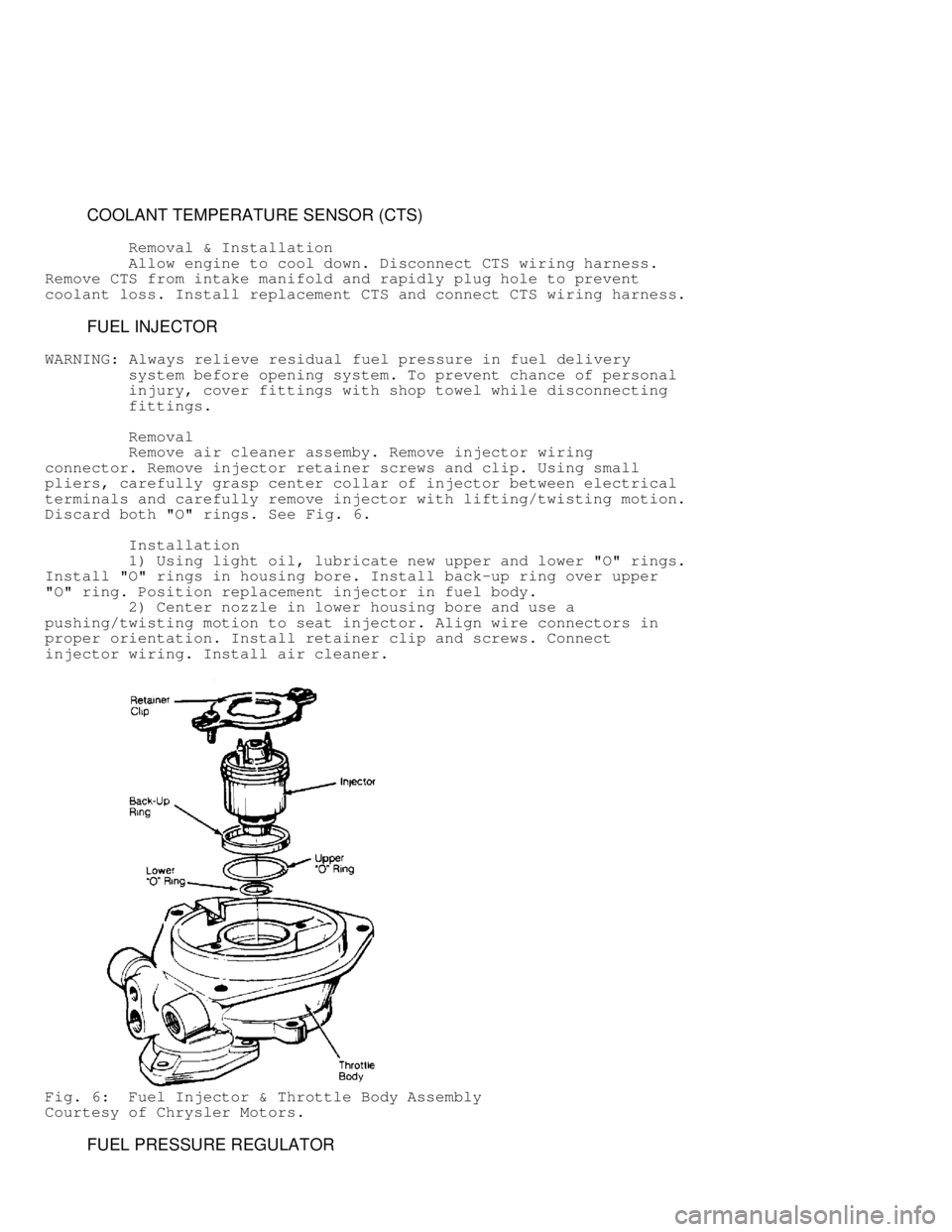
Discard both "O" rings. See Fig. 6.
Installation
1) Using light oil, lubricate new upper and lower "O" rings.
Install "O" rings in housing bore. Install back-up ring over upper
"O" ring. Position replacement injector in fuel body.
2) Center nozzle in lower housing bore and use a
pushing/twisting motion to seat injector. Align wire connectors in
proper orientation. Install retainer clip and screws. Connect
injector wiring. Install air cleaner.
Fig. 6: Fuel Injector & Throttle Body Assembly
Courtesy of Chrysler Motors.
FUEL PRESSURE REGULATOR
Page 803 of 1378

Removal & Installation
WARNING: Always relieve residual fuel pressure in fuel delivery
system before opening system. To prevent chance of personal
injury, cover fittings with shop towel while disconnecting
fittings.
With throttle body assembly removed, remove 3 screws holding
fuel pressure regulator in throttle body. Remove fuel pressure
regulator assembly. Note location of components for installation.
Discard gaskets. To install, reverse removal procedure. Adjust
regulator after installation. See ADJUSTMENTS in this article.
IDLE SPEED ACTUATOR (ISA) MOTOR
Removal & Installation
1) Disconnect throttle return spring. Disconnect wiring
harness connector from ISA motor. Remove ISA motor retaining nuts and
remove ISA motor from bracket.
2) To install ISA motor assembly, reverse removal procedure.
Adjust ISA motor after installation. See ADJUSTMENTS in this article.
THROTTLE BODY ASSEMBLY
Removal
1) Remove air inlet duct and adapter plate. Remove throttle
cable and return spring. Disconnect electrical leads from fuel
injector, WOT switch, and ISA motor.
2) Disconnect fuel supply and return lines at throttle body.
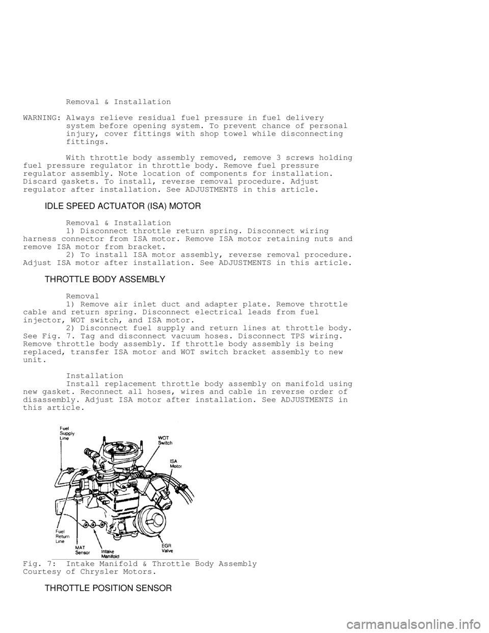
See Fig. 7 . Tag and disconnect vacuum hoses. Disconnect TPS wiring.
Remove throttle body assembly. If throttle body assembly is being
replaced, transfer ISA motor and WOT switch bracket assembly to new
unit.
Installation
Install replacement throttle body assembly on manifold using
new gasket. Reconnect all hoses, wires and cable in reverse order of
disassembly. Adjust ISA motor after installation. See ADJUSTMENTS in
this article.
Fig. 7: Intake Manifold & Throttle Body Assembly
Courtesy of Chrysler Motors.
THROTTLE POSITION SENSOR
Page 804 of 1378

Removal & Installation
Remove throttle body assembly as previously described.
Remove Torx head retaining screws. Remove throttle position sensor
from throttle shaft lever. To install, reverse removal procedure.
Adjust TPS after installation. See ADJUSTMENTS in this article.
MANIFOLD AIR/FUEL TEMPERATURE (MAT) SENSOR
Removal & Installation
Disconnect wire harness connector from MAT sensor. Remove
MAT sensor from intake manifold. To install, reverse removal
procedure. See Fig. 7.
MANIFOLD ABSOLUTE PRESSURE (MAP) SENSOR
Removal & Installation
Disconnect wire harness connector, vacuum hose, and
retaining nuts from MAP sensor. Remove sensor from firewall. To
install, reverse removal procedure.
ELECTRONIC CONTROL UNIT (ECU)
Removal & Installation
1) On Wrangler, remove passenger assist handle and glove box
assembly. Remove ECU bracket retaining nuts from engine compartment
side of firewall. Disconnect ECU wiring harness. Remove ECU from
bracket. To install, reverse removal procedure.
2) On all other models, remove retaining screws and bracket
that supports ECU above accelerator pedal. Remove ECU and disconnect
wiring harness. To install, reverse removal procedure.
EGR VALVE
Removal & Installation
Disconnect vacuum hose from EGR valve. Remove bolts which
hold EGR valve to intake manifold. Remove valve and discard gasket.
To install valve, reverse removal procedure. Always use new gasket.
See Fig. 7 .
TROUBLESHOOTING AND DIAGNOSIS
Page 821 of 1378
Fig. 24: TEST 6: MANUAL TRANSMISSION UPSHIFT
WIRING DIAGRAMS
Page 822 of 1378
Fig. 25: Cherokee, Comanche & Wagoneer Throttle Body Fuel
Injection System Wiring Diagram
Page 823 of 1378
Fig. 26: Wrangler Throttle Body Fuel Injection System Wiring Diagram