Page 829 of 1378

1 - 25 Amp
Rear Washer/Wiper.
2 - 15 Amp
Radio, Cigarette Lighter.
3 - 25 Amp
Blower Motor.
4 - 20 Amp
Turn Signal, Back-Up Lights, Rear Window Defogger Relay.
5 - 10 Amp
Dome Light, Courtesy Lights, Glove Box Light, Cargo Light,
Radio Memory, Power Mirrors, Teltak Connector.
6 - 15 Amp
Hazard Warning System, Stoplights.
7 - 10 Amp
Parking Lights, Headlight Warning Chime/Buzzer, Instrument
Panel Light Dimmer.
8 - 7.5 Amp
Gauges, Instrument Cluster, Seat Belt Warning, Headlight
Delay, Chime Module, Overhead Console.
9 - 5 Amp
Instrument Panel Illumination.
10 - 25 Amp
Rear Window Defogger.
11 - 30 Amp (Circuit Breaker)
Power Door Locks, Power Seats, Trailer Towing Wiring Harness.
12 - 10 Amp
ETR Radio, Power Antenna.
13 - Not Used (1984-87); 7.5 Amp (1988)
Transmission Control Unit.
14 - 25 Amp
Headlight Delay, Horns, Security Alarm.
15 - 5.5 Amp (Circuit Breaker)
Front Wiper.
16 - 30 Amp (Circuit Breaker)
Power Windows.
17 - 10 Amp
Clock, Security Alarm (Ign).
CAUTIONS & WARNINGS
REPLACING BLOWN FUSES
Before replacing a blown fuse, remove ignition key, turn off
all lights and accessories to avoid damaging the electrical system. Be
sure to use fuse with the correct indicated amperage rating. The use
of an incorrect amperage rating fuse may result in a dangerous
Page 842 of 1378

� LEVER � � BLOWER � PANEL � FLOOR � DEFROST � WATER �
�
POSITION �AIR DISCHARGE� SPEEDS � DOOR � DOOR � DOOR � VALVE �
�
������������������\
��\b����������������\
�����������\b�������\
����������\b��������\
�������\b�����������\
����\b��������������\
�����\b�������������\
����
�
Off � Closed � None � Closed� Closed� Closed � Closed �
�
������������������\
��\b����������������\
�����������\b�������\
����������\b��������\
�������\b�����������\
����\b��������������\
�����\b�������������\
����
�
Vent � Panel � 4 � Open � Closed� Closed � Closed �
�
� Registers � � � � � �
�
������������������\
��\b����������������\
�����������\b�������\
����������\b��������\
�������\b�����������\
����\b��������������\
�����\b�������������\
����
�
Bi-Level � Panel � 4 � Open � Open � Bleed � Open
(1)�
�
� Registers � � � � � �
�
� and Floor � � � � � �
�
� With Def. � � � � � �
�
� Bleed � � � � � �
�
������������������\
��\b����������������\
�����������\b�������\
����������\b��������\
�������\b�����������\
����\b��������������\
�����\b�������������\
����
�
Heat � Floor With � 4 � Closed� Open � Bleed � Open
(1)�
�
� Def. Bleed � � � � � �
�
������������������\
��\b����������������\
�����������\b�������\
����������\b��������\
�������\b�����������\
����\b��������������\
�����\b�������������\
����
�
Def. � Defroster � 4 � Closed� Closed� Open � Open
(1)�
�
� � � � � � �
�
������������������\
��
����������������\
�����������
�������\
����������
��������\
�������
�����������\
����
��������������\
�����
�������������\
����
�
(1)
- Water valve closes in full "COOL" temperature lever position. �
�
������������������\
������������������\
������������������\
������������������\
������������������\
������������������\
������������������\
����������\f
Fig. 3: Heater Control System Vacuum Diagram
WIRING DIAGRAMS
Page 843 of 1378
Fig. 4: Heater Wiring Diagram (Comanche Diesel)
Page 844 of 1378
Fig. 5: Heater Wiring Diagram (Comanche Gas)
Fig. 6: Heater Wiring Diagram (Wrangler)
Page 864 of 1378
 Test ECU terminal \"C-6\" for the same voltage as described
in step 2) to verify the wiring harn")
Fig. 15. With a hot idle condition, the voltage reading should drop to
between 0.5-1.5 volts.
3) Test ECU terminal "C-6" for the same voltage as described
in step 2) to verify the wiring harness. Repair as necessary.
4) Test the MAP sensor supply voltage at the sensor connector
terminal "C" with the ignition ON. Voltage reading should be between
4.5-5.5 volts. Check that the voltage reading at terminal "C-14" is
also 4.5-5.5 volts.
5) Repair or replace the wire harness as necessary.
6) Test the MAP sensor ground circuit at the sensor connector
terminal "A" and ECU connector terminal "D-3". Repair the wire harness
as necessary.
7) Using an ohmmeter, test the MAP sensor ground circuit at
the ECU connector between terminal "D-3" and terminal "B-ll". If an
open circuit is indicated, check for a defective sensor ground
connection. The MAP sensor ground is located on the right side of the
engine block.
8) If, after performing step 7), the ground connection is
verified to be good, check for a short to 12 volts at terminal "D-3".
If a short is found, repair the short and then replace the ECU.
KNOCK SENSOR TEST
1) Connect Diagnostic Tester M.S. 1700 to the vehicle.
2) Go to "State Display" mode.
3) Start the engine and let idle.
4) Observe knock sensor value.
5) Using the tip of a screwdriver, lightly tap the cylinder
block near the sensor while observing the knock sensor value.
6) The knock sensor value should increase when the cylinder
block is tapped.
7) If the knock sensor value does not increase while tapping
on the cylinder block near the knock sensor, check for proper
connections to the knock sensor. If connections are good, replace
the knock sensor. Refer to REMOVAL & INSTALLATION in this article.
ENGINE SPEED SENSOR TEST
1) Disconnect the engine speed sensor connector from the
ignition control module.
2) place an ohmmeter between terminals "A" and "B" (marked on\
the connector). On a hot engine, the resistance reading should be
between 125-275 ohms.
3) Replace sensor if readings are not within specification.
Fig. 16: View of Engine Speed Sensor Connectors (At Sensor)
Courtesy of Chrysler Motors.
Page 871 of 1378
housing with 2 shoulder bolts. Tighten the engine speed sensor
shoulder bolts.
2) Connect the engine speed sensor wire connector.
ELECTRONIC CONTROL UNIT (ECU)
Removal
NOTE: The ECU is located below the instrument panel, between
the steering column and the A/C-Heater housing. See
Fig. 22. Three screws mount the ECU to a bracket.
1) Disconnect the negative battery cable.
2) Remove the 3 ECU attaching screws. See Fig. 23.
3) Disconnect the ECU wiring harness connector.
4) Remove the ECU.
Fig. 22: Location of ECU
Courtesy of Chrysler Motors.
Page 872 of 1378
Fig. 23: Location of ECU Mounting Screws
Courtesy of Chrysler Motors.
Installation
1) Connect the ECU wiring harness connector.
2) While holding the ECU in position, attach the 3 ECU
attaching screws. See Fig. 23.
3 Connect the negative battery cable.
DISTRIBUTOR
Page 880 of 1378
\003
IG NIT IO N S YSTE M - 4 .0 L W /H EI/E ST/E SC ( D ELC O -R EM Y)
�
1 988 J e ep C hero ke e
Distributors & Ignition Systems
HEI, HEI/EST & HEI/EST/ESC IGNITION SYSTEM
Jeep 4.0L
DESCRIPTION
HIGH ENERGY IGNITION (HEI)
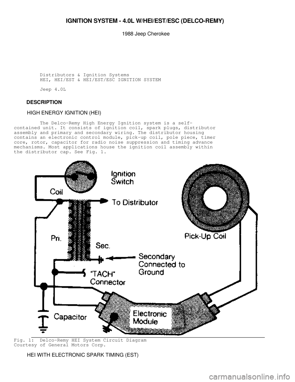
The Delco-Remy High Energy Ignition system is a self-
contained unit. It consists of ignition coil, spark plugs, distributor
assembly and primary and secondary wiring. The distributor housing
contains an electronic control module, pick-up coil, pole piece, timer
core, rotor, capacitor for radio noise suppression and timing advance
mechanisms. Most applications house the ignition coil assembly within
the distributor cap. See Fig. 1.
Fig. 1: Delco-Remy HEI System Circuit Diagram
Courtesy of General Motors Corp.
HEI WITH ELECTRONIC SPARK TIMING (EST)
")

Fig. 6: Heater Wiring Diagram (Wrangler)")
 Connect the engine speed sensor wire connector.
ELECTRONIC CONTROL UNIT (ECU)
Removal
NOTE")
 Connect the ECU wiring harness connector.
2) While holding the ECU in position, attach")