Page 165 of 1378

Information pertaining to Sanden compressors in this article,
will be found in earlier articles under Sankyo compressors.
AMERICAN MOTORS & JEEP WITH 5-CYLINDER COMPRESSOR
Compressor Overhaul
1) After the compressor and system have been run, stop the
engine. Slowly discharge system using approved refrigerant
recovery/recycling equipment. Clean and cool dipstick with R-12.
2) Loosen the compressor mounting bolts, remove the drive
belt, and move the compressor to a bench for easiest and most accurate
measurement. Position the compressor so that the oil fill plug is at
top dead center.
3) Thoroughly clean the oil fill plug and the area around it.
Loosen the fill plug slowly to allow trapped refrigerant pressure to
escape through the loosened threads.
4) The front plate hub has a lobe, which is indexed (notched)\
180
� from TDC of the cam rotor. Rotate the hub plate lobe until the
index notch is 110� from bottom center. See Fig. 1. Check this
position by looking through the oil fill hole and noting that the ball
end of the top piston rod lines up with the fill hole.
5) Looking at the front end of the compressor, insert the
dipstick diagonally from upper left to lower left until the dipstick
stop contacts the filler hole surface. Remove dipstick and note oil
level. Oil level should be between the 4th and 6th increment on the
dipstick (3-4 ounces). Add oil as necessary.
Compressor Replacement
If system was opened by a leak or so quickly that oil was
lost, install new compressor with all the oil it contains. If system
was opened slowly and oil was not lost, drain oil from new compressor
and measure. Reinstall 6 ounces of oil back into new compressor prior
to installation.
Component Replacement
If a hose, receiver-drier, condenser, expansion valve or
evaporator core requires replacement, add 1 ounce of new oil for each
new component installed.
Compressor Oil Check
1) Discharge system, using approved refrigerant
recovery/recycling equipment, or isolate compressor. Remove oil filler
plug. Look through oil filler plug hole and rotate clutch front plate
to position piston connecting rod in center of oil filler plug hole.
2) Insert dipstick (J-29642-12) through oil filler plug hole\
to the right of piston connecting rod until dipstick stop contacts the
compressor housing.
3) Remove dipstick and count number of increments covered
with oil. If compressor is properly filled, oil will cover 4-6
increments on the dipstick. Adjust oil level as necessary.
Page 166 of 1378
Fig. 1: 5-Cylinder Compressor Oil Check (Use dipstick J-29642-12)
YORK 2-CYLINDER COMPRESSOR SERVICING
JEEP WITH 2-CYLINDER COMPRESSOR
Page 176 of 1378
Without A/C ........................... 4.4 (4.2)
Jeep
Cherokee & Wagoneer (2)
4-Cylinder ........................... 10.0 (9.5)
V6 .................................. 12.0 (11.4)
CJ & Scrambler
4-Cylinder ............................ 9.0 (8.5)
6-Cylinder ........................... 10.5 (9.9)
Grand Wagoneer & Truck (3)
6-Cylinder .......................... 12.5 (11.8)
V8 .................................. 15.5 (14.7)
(1) - May vary +/- 15% due to system variations.
(2) - Includes 2.3 qts. (2.2L) in recovery bottle.
(3) - Includes 1 qt. (.9L) for heater.
������������������\
������������������\
������������������\
������������������\
������������������\
������������������\
�
Page 266 of 1378
used with 2.5.L
The DRB-II has determined that the wrong Transmission Control
Unit (TCU) has been installed in the vehicle. There are two
transmission control units available for the Jeep AW4 transmission.
One is for the 4-cylinder 2.5L engine and the other is for the 6-
cylinder 4.0L engine.
1) using the DRB-II, read MODULE INFO. See HELP 1 for
assistance.
2) Determine what vehicle should be in the vehicle.
* 2.5L Engine: TCU 02 (Used in earlier years only)
* 4.0L Engine: TCU 01 (1993-94)
3) If the wrong transmission control unit is installed, the
vehicle shift points will be slightly different (the 2.5L engine TCU
has higher shift points).
TEST 10A - TESTING FOR INTERMITTENT SPEED SENSOR
NOTE: Perform TEST 1A - VERIFICATION OF THE COMPLAINT
before proceeding.
Fig. 115: Test 10A - Flow Chart (1 of 2)
Fig. 116: Test 10A - Schematic (Cherokee)
Page 277 of 1378

BRAK E S YSTE M B LE ED IN G
�
1988 J e ep C hero ke e
1988 BRAKES
Jeep - Brake System Bleeding
Cherokee, Comanche, Grand Wagoneer, Wagoneer, Wrangler
BRAKE SYSTEM BLEEDING
Hydraulic system bleeding is necessary any time air has been
introduced into system. Bleed brakes at all 4 wheels if master
cylinder lines have been disconnected or master cylinder has run dry.
Bleed brakes with vacuum bleeding equipment, pressure bleeding
equipment or by manually pumping brake pedal while using bleeder
tubes. Always bleed brake lines in sequence. See BLEEDING SEQUENCE
table.
MASTER CYLINDER BLEEDING
Bench Bleeding
1) Master cylinder must be bled before installation to
prevent excessive amounts of air from entering the brake system,
creating poor brake operation.
2) Place master cylinder in soft-jawed vise. DO NOT tighten
vise enough to damage master cylinder. Install bleeder tubes in both
outlets of master cylinder. See Fig. 1.
Fig. 1: Bleeding Master Cylinder
Courtesy of American Motors/Jeep Corp.
3) Fill master cylinder with clean brake fluid that meets DOT
3 specifications. Ensure that the end of bleeder tubes are submerged
Page 278 of 1378
 Using proper sized rod, apply and release master cylinder
until no air bubbles exist in brake fluid flow. Once all air bubbles
are gone from master cylinder secure cap")
in the brake fluid.
4) Using proper sized rod, apply and release master cylinder
until no air bubbles exist in brake fluid flow. Once all air bubbles
are gone from master cylinder secure cap and install.
5) Bleeder tubes should be left installed on master cylinder
until master cylinder in installed. Master cylinder must be bled at
brake lines and wheels after installation.
Bleeding On Vehicle
1) Install master cylinder on vehicle after bench bleeding.
Remove bleeder lines and install brake lines. DO NOT fully tighten
brake lines at this time.
2) Slowly force brake pedal to the floor and hold in this
position. Tighten brake lines and release brake pedal. Repeat
procedure until no air bubbles exist at brake lines. Remaining wheel
cylinder or calipers may be require bleeding.
HYDRAULIC CONTROL VALVES
Hold Off Valve
1) Prior to the pressure tank bleeding procedure, the hold
off valve incorporated in the combination valve must be correctly
positioned. This allows brake fluid to flow through the combination
valve to the entire brake system.
2) The valve stem of the hold off valve may be retained using
tools available from Chrysler Motors (C-4121) or General Motors
(J-23709) during bleeding procedure. See Figs. 2 and 3. Remove valve
retainer once brake bleeding procedure is complete.
CAUTION: DO NOT use rigid clamp to position valve stem. Damage to
the valve assembly may result causing brake failure.
Fig. 2: Positioning Hold Off Valve
Courtesy of American Motors/Jeep Corp.
Page 279 of 1378

Fig. 3: Positioning Hold Off Valve
Courtesy of American Motors/Jeep Corp.
VACUUM BLEEDING
Fill master cylinder. Install vacuum bleed equipment to first
bleeder valve to be serviced. Open bleeder valve 3/4-1 turn. Depress
vacuum pump and pull fluid into reservoir jar. Bleed each bleeder
valve in sequence. See BLEEDING SEQUENCE table.
PRESSURE BLEEDING
1) Clean master cylinder cap and surrounding area. Remove
cap. With pressure tank at least 1/2 full, connect to master cylinder
with adapters. Attach bleeder hose to first bleeder valve to be
serviced. See BLEEDING SEQUENCE table.
2) Place other end of hose in clean glass jar partially
filled with clean brake fluid so end of hose is submerged in fluid.
The hold off valve must be positioned properly before pressure
bleeding (if equipped). See HYDRAULIC CONTROL VALVES under BRAKE
SYSTEM BLEEDING in this article.
3) Open release valve on pressure bleeder. Follow equipment
manufacturer's pressure instructions or see PRESSURE BLEEDER SETTINGS
table. Open bleeder screw 3/4-1 turn and note fluid flow.
4) Close bleeder screw when fluid flowing is free of bubbles.
Repeat procedure on remaining wheels in proper sequence. Check brake
pedal operation after bleeding has been completed.
5) Remove pressure bleeding equipment and valve retainer from
hold off valve. Ensure that master cylinder is full of fluid.
PRESSURE BLEEDER SETTINGS TABLE
������������������\
������������������\
������������������\
������������������\
������������������\
������������������\
�����������
Application psi (kg/cm�)
Page 280 of 1378
All Models ............................... 15-20 (1.1-1.4)������������������\
������������������\
������������������\
������������������\
������������������\
������������������\
�����������
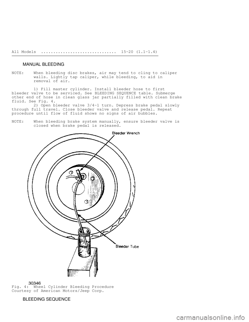
MANUAL BLEEDING
NOTE: When bleeding disc brakes, air may tend to cling to caliper
walls. Lightly tap caliper, while bleeding, to aid in
removal of air.
1) Fill master cylinder. Install bleeder hose to first
bleeder valve to be serviced. See BLEEDING SEQUENCE table. Submerge
other end of hose in clean glass jar partially filled with clean brake
fluid. See Fig. 4.
2) Open bleeder valve 3/4-1 turn. Depress brake pedal slowly
through full travel. Close bleeder valve and release pedal. Repeat
procedure until flow of fluid shows no signs of air bubbles.
NOTE: When bleeding brake system manually, ensure bleeder valve is
closed when brake pedal is released.
Fig. 4: Wheel Cylinder Bleeding Procedure
Courtesy of American Motors/Jeep Corp.
BLEEDING SEQUENCE

YORK 2-CYLINDER COMPRESSOR SERVICING
JEEP WITH 2-CYLINDER COMPRESSOR")

Jeep
Cherokee & Wagoneer (2)
4-Cylinder ........................... 10.0 (9.5)
V6 .................................. 12.0 (11.4)")
 has been installed in the vehicle. There are two
transmission control units available for the J")