1988 JEEP CHEROKEE oil type
[x] Cancel search: oil typePage 163 of 1378

CAN TAP INSTALLATION
FLAT TYPE SEAL CANS
On cam-lock or one-piece can taps, first turn the handle out
to the fully open position. Securely engage the locking lugs over the
flange of the can, and lock them in place by turning the cam lock or
locking nut. Screw the tap assembly into the adapter so the sealing
gasket is fully seated against the can top. Turn the tap inward to
pierce the can and close the tap. DO NOT open the tap until ready to
purge the service hose or dispense refrigerant into the system.
On 2-piece can taps, be certain the tap handle is turned
fully in, so it is closed. Check that the locking base is turned to
its outer limit. Securely engage the locking lugs over the can
flange. Turn the entire tap assembly (without disturbing the closed
setting) down into the locking base to pierce the can. Do not open
the tap until ready to dispense into system.
SCREW TYPE SEAL CANS
Ensure can tap is fully closed. Screw refrigerant can into
can tap fitting until tight. This will pierce the can. Connect tap to
center hose on manifold gauge set. DO NOT open tap until ready to
dispense R-12 into system.
WARNING: DO NOT open high side hand valve while air conditioning
system is in operation. This high pressure could rupture
can or possibly burst fitting at safety can valve,
resulting in damage and physical injury.
COMPRESSOR OIL CHECK
GENERAL PROCEDURES
Some models have compressor-mounted service valves that allow
oil checking by isolating the compressor. On all others, system must
be discharged, using approved refrigerant recovery/recycling
equipment, and compressor may need to be removed to check oil. After
oil level is checked and adjusted, A/C system must be evacuated and
recharged.
ISOLATING COMPRESSOR
1) Connect manifold gauge set to service valves on the
compressor. Close both gauge valves. Open both service valves to
themid-position.
2) Start engine and operate air conditioning. Turn suction
service valve slowly clockwise toward front-seated position. When
suction pressure is reduced to zero or less, stop engine and quickly
close suction service valve (front-seated).
3) Front-seat the discharge valve. Loosen oil check plug
slowly to release any internal pressure. Service valves can now be
removed from compressor and compressor removed from vehicle (if
necessary). Purge compressor after servicing.
PURGING COMPRESSOR
1) Remove gauge set and place caps on service valve ports.
Back-seat the suction service valve to allow refrigerant to enter
compressor.
Page 436 of 1378

FLANGES
FLEX PLATES
FLUID LEVEL INDICATORS
FLUIDS AND LUBRICANTS
FLYWHEELS
FORCE MOTORS
GUIDES
HALF SHAFTS
HOSES, LINES AND TUBES
HOUSINGS (BELL, CASE, TAIL (EXTENSION) AND AUXILIARY)
INTERMEDIATE SHAFT SUPPORT BEARINGS
KEY INTERLOCK SYSTEMS
LIMITED SLIPS
LINES
LINKAGES (EXTERNAL)
LOCKING HUB ASSEMBLIES
LOCKING HUB CONTROL KNOBS
LUBRICANTS
METAL-CLAD SEALS
METALASTIC JOINTS
MODULATOR PINS
MODULATORS
MOUNTS (ENGINE, TRANSAXLE AND TRANSMISSION)
ODOMETER DRIVES (MECHANICAL)
ODOMETER HEADS (MECHANICAL)
OIL PANS
PANS
PILOT HOLES
PRESSURE PLATES
PRESSURE SWITCHES
RACES
RUBBER JOINTS (METALASTIC)
SCREENS
SEALS
SEALS (METAL-CLAD)
SELECTOR INTERLOCK SYSTEMS
SERVOS
SHIFT INTERLOCK SYSTEMS (SELECTOR AND KEY INTERLOCK SYSTEMS)
SENSORS
SIDE COVERS
SLIP YOKES
SOLENOIDS
SPEED SENSORS (ELECTRONIC WHEEL AND VEHICLE)
SPEEDOMETER-DRIVEN GEAR HOUSINGS
SPEEDOMETER/ODOMETER DRIVES (MECHANICAL)
SPEEDOMETER/ODOMETER HEADS (MECHANICAL)
SPEEDOMETERS AND ODOMETERS (ELECTRONIC)
SWITCHES
TONE WHEELS
TOOTHED RINGS (TONE WHEELS)
TORQUE CONVERTERS
TRANSAXLE MOUNTS
TRANSDUCERS (TRANSMISSION)
TRANSMISSION COOLERS
TRANSMISSION MOUNTS
TRANSMISSION PANS
TRANSMISSION RANGE INDICATORS (PRNDL)
TUBES
UNIVERSAL JOINTS (CARDON OR CROSS TYPE)
VACUUM CONTROLS
VACUUM HOSES
VACUUM MOTORS
VACUUM-OPERATED SWITCHES
Page 611 of 1378

rust may be removed using bead blasting method. Components must be
free of oil and grease prior to bead blasting. Beads will stick to
grease or oil soaked areas causing area not to be cleaned.
Use air pressure to remove all trapped residual beads from
components after cleaning. After cleaning internal engine parts made
of aluminum, wash thoroughly with hot soapy water. Component must be
thoroughly cleaned as glass beads will enter engine oil resulting in
bearing damage.
CHEMICAL CLEANING
Solvent tank is used for cleaning oily residue from
components. Solvent blasting sprays solvent through a siphon gun using
compressed air.
The hot tank, using heated caustic solvents, is used for
cleaning ferrous materials only. DO NOT clean aluminum parts such as
cylinder heads, bearings or other soft metals using the hot tank.
After cleaning, flush parts with hot water.
A non-ferrous part will be ruined and caustic solution will
be diluted if placed in the hot tank. Always use eye protection and
gloves when using the hot tank.
Use of a cold tank is for cleaning of aluminum cylinder
heads, carburetors and other soft metals. A less caustic and unheated
solution is used. Parts may be lift in the tank for several hours
without damage. After cleaning, flush parts with hot water.
Steam cleaning, with boiling hot water sprayed at high
pressure, is recommended as the final cleaning process when using
either hot or cold tank cleaning.
COMPONENT CLEANING
* PLEASE READ THIS FIRST *
NOTE: Always refer to appropriate engine overhaul article in the
ENGINES section for complete overhaul procedures and
specifications for the vehicle being repaired.
SHEET METAL PARTS
Examples of sheet metal parts are the rocker covers, front
and side covers, oil pan and bellhousing dust cover. Glass bead
blasting or hot tank may be used for cleaning.
Ensure all mating surfaces are flat. Deformed surfaces should
be straightened. Check all sheet metal parts for cracks and dents.
INTAKE & EXHAUST MANIFOLDS
Using solvent cleaning or bead blasting, clean manifolds for
inspection. If the intake manifold has an exhaust crossover, all
carbon deposits must be removed. Inspect manifolds for cracks, burned
or eroded areas, corrosion and damage to fasteners.
Exhaust heat and products of combustion cause threads of
fasteners to corrode. Replace studs and bolts as necessary. On "V"
type intake manifolds, the sheet metal oil shield must be removed for
proper cleaning and inspection. Ensure that all manifold parting
surfaces are flat and free of burrs.
CYLINDER HEAD REPLACEMENT
* PLEASE READ THIS FIRST *
Page 612 of 1378

NOTE: Always refer to appropriate engine overhaul article in the
ENGINES section for complete overhaul procedures and
specifications for the vehicle being repaired.
REMOVAL
Remove intake and exhaust manifolds and valve cover. Cylinder
head and camshaft carrier bolts (if equipped), should be removed only
when the engine is cold. On many aluminum cylinder heads, removal
while hot will cause cylinder head warpage. Mark rocker arm or
overhead cam components for location.
Remove rocker arm components or overhead cam components.
Components must be installed in original location. Individual design
rocker arms may utilize shafts, ball-type pedestal mounts or no rocker
arms. For all design types, wire components together and identify
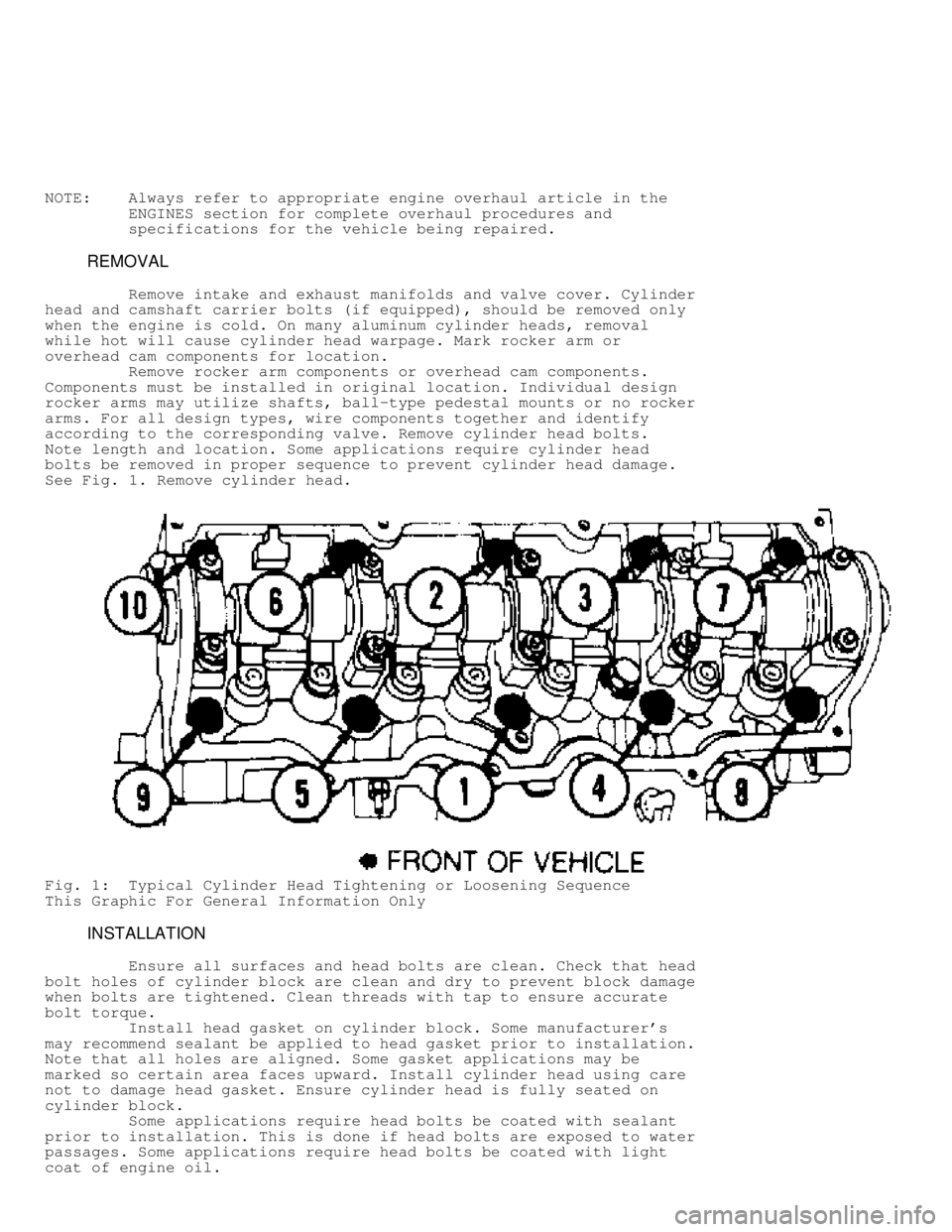
according to the corresponding valve. Remove cylinder head bolts.
Note length and location. Some applications require cylinder head
bolts be removed in proper sequence to prevent cylinder head damage.
See Fig. 1 . Remove cylinder head.
Fig. 1: Typical Cylinder Head Tightening or Loosening Sequence
This Graphic For General Information Only
INSTALLATION
Ensure all surfaces and head bolts are clean. Check that head
bolt holes of cylinder block are clean and dry to prevent block damage
when bolts are tightened. Clean threads with tap to ensure accurate
bolt torque.
Install head gasket on cylinder block. Some manufacturer's
may recommend sealant be applied to head gasket prior to installation.
Note that all holes are aligned. Some gasket applications may be
marked so certain area faces upward. Install cylinder head using care
not to damage head gasket. Ensure cylinder head is fully seated on
cylinder block.
Some applications require head bolts be coated with sealant
prior to installation. This is done if head bolts are exposed to water
passages. Some applications require head bolts be coated with light
coat of engine oil.
Page 615 of 1378

On cast cylinder heads, if warpage exceeds .003" (.08 mm)
in a 6" span, or .006" (.15 mm) over total length, cylinder head must
be resurfaced. On most aluminum cylinder heads, if warpage exceeds .
002" (.05 mm) in any area, cylinder head must be resurfaced. Warpage
specification may vary with manufacturer.
Cylinder head thickness should be measured to determine
amount of material which can be removed before replacement is
required. Cylinder head thickness must not be less than manufacturer's
specifications.
If cylinder head required resurfacing, it may not align
properly with intake manifold. On "V" type engines, misalignment is
corrected by machining intake manifold surface that contacts cylinder
head. Cylinder head may be machined on surface that contacts intake
manifold.
Using oil stone, remove burrs or scratches from all sealing
surfaces.
VALVE SPRINGS
Inspect valve springs for corroded or pitted valve spring
surfaces which may lead to breakage. Polished spring ends caused by
a rotating spring, indicates that spring surge has occurred. Replace
springs showing evidence of these conditions.
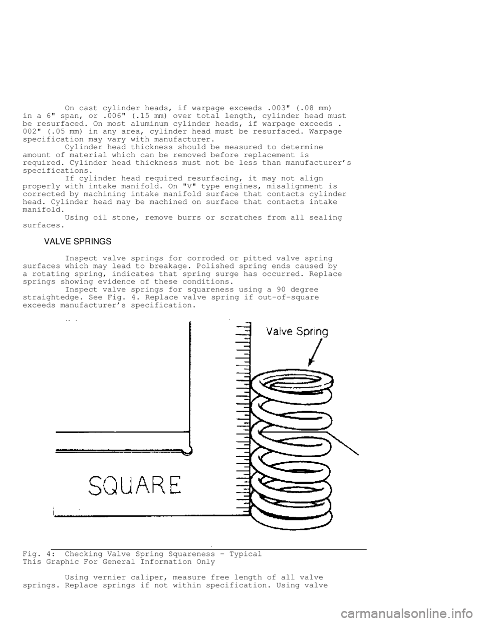
Inspect valve springs for squareness using a 90 degree
straightedge. See Fig. 4. Replace valve spring if out-of-square
exceeds manufacturer's specification.
Fig. 4: Checking Valve Spring Squareness - Typical
This Graphic For General Information Only
Using vernier caliper, measure free length of all valve
springs. Replace springs if not within specification. Using valve
Page 623 of 1378

ROCKER ARMS & ASSEMBLIES
Rocker Studs
Rocker studs are either threaded or pressed in place.
Threaded studs are removed by locking 2 nuts on the stud. Unscrew the
stud by turning the jam nut. Coat the stud threads with Loctite and
install. Tighten to specification.
Pressed in stud can be removed using a stud puller. Ream the
stud bore to proper specification and press in a new oversize stud.
Pressed in studs are often replaced by cutting threads in the stud
bore to accept a threaded stud.
Rocker Arms & Shafts
Mark rocker arms for location. Remove rocker arm retaining
bolts. Remove rocker arms. Inspect rocker arms, shafts, bushings and
pivot balls (if equipped) for excessive wear. Inspect rocker arms
for wear in valve stem contact area. Measure rocker arm bushing I.D.
Replace bushings if excessively worn.
The rocker arm valve stem contact point can be reground,
using special fixture for valve grinding machine. Remove minimum
amount of material as possible. Ensure all oil passages are clear.
Install rocker arms in original locations. Ensure rocker arm is
properly seated in push rod. Tighten bolts to specification. Adjust
valves if required. See VALVE ADJUSTMENT in this article.
Pushrods
Remove rocker arms. Mark push rods for location. Remove push
rods. Push rods can be steel or aluminum, solid or hollow. Hollow
pushrods must be internally cleaned to ensure oil passage to the
rocker arms is cleaned. Check the pushrod for damage, such as loose
ends on steel tipped aluminum types.
Check push rod for straightness. Roll push rod on a flat
surface. Using feeler gauge, check clearance at center. Replace push
rod if bent. The push rod can also be supported at each end and
rotated. A dial indicator is used to detect bends in the push rod.
Lubricate ends of push rod and install push rod in original
location. Ensure push rod is properly seated in lifter. Install rocker
arm. Tighten bolts to specification. Adjust valves if required. See
VALVE ADJUSTMENT in this article.
LIFTERS
Hydraulic Lifters
Before replacing a hydraulic lifter for noisy operation,
ensure noise is not caused by worn rocker arms or valve tips.
Hydraulic lifter assemblies must be installed in original locations.
Remove the rocker arm assembly and push rod. Mark components for
location. Some applications require intake manifold, or lifter cover
removal. Remove lifter retainer plate (if used). To remove lifters,
use a hydraulic lifter remover or magnet. Different type lifters are
used. See Fig. 13.
Page 625 of 1378

interchangeable. Inspect all components for wear. Note amount of wear
in lifter body-to-camshaft contact area. Surface must have smooth and
convex contact face. If wear is apparent, carefully inspect cam lobe.
Inspect push rod contact area and lifter body for scoring
or signs of wear. If body is scored, inspect lifter bore for damage
and lack of lubrication. On roller type lifters, inspect roller for
flaking, pitting, loss of needle bearings and roughness during
rotation.
Measure lifter body O.D. in several areas. Measure lifter
bore I.D. of cylinder block. Some models offer oversized lifters.
Replace lifter if damaged.
If lifter check valve is not operating, obstructions may be
preventing it from closing or valve spring may be broken. Clean or
replace components as necessary.
Check plunger operation. Plunger should drop to bottom of the
body by its own weight when assembled dry. If plunger is not free,
soak lifter in solvent to dissolve deposits.
Lifter leak-down test can be performed on lifter. Lifter
must be filled with special test oil. New lifters contain special test
oil. Using lifter leak-down tester, perform leak-down test following
manufacturer's instructions. If leak-down time is not within
specifications, replace lifter assembly.
Lifters should be soaked in clean engine oil several hours
prior to installation. Coat lifter base, roller (if equipped) and
lifter body with ample amount of Molykote or camshaft lubricant. See
Fig. 13. Install lifter in original location. Install remaining
components. Valve lash adjustment is not required on most hydraulic
lifters. Preload of hydraulic lifter is automatic. Some models may
require adjustment.
Mechanical Lifters
Lifter assemblies must be installed in original locations.
Remove rocker arm assembly and push rod. Mark components for location.
Some applications require intake manifold or lifter cover removal.
Remove lifter retainer plate (if used). To remove lifters, use lifter
remover or magnet.
Inspect push rod contact area and lifter body for scoring or
signs of wear. If body is scored, inspect lifter bore for damage and
lack of lubrication. Note amount of wear in lifter body-to-camshaft
contact area. Surface must have smooth and convex contact face. If
wear is apparent, carefully inspect cam lobe.
Coat lifter base, roller (if equipped) and lifter body with
ample amount of Molykote or camshaft lubricant. Install lifter in
original location. Install remaining components. Tighten bolts to
specification. Adjust valves. See VALVE ADJUSTMENT in this article.
PISTONS, CONNECTING RODS & BEARINGS
* PLEASE READ THIS FIRST *
NOTE: Always refer to appropriate engine overhaul article in the
ENGINES section for complete overhaul procedures and
specifications for the vehicle being repaired.
RIDGE REMOVAL
Ridge in cylinder wall must be removed prior to piston
removal. Failure to remove ridge prior to removing pistons will cause
piston damage in piston ring locations.
With the piston at bottom dead center, place a rag in the
bore to trap metal chips. Install ridge reamer in cylinder bore.
Adjust ridge reamer using manufacturer's instructions. Remove ridge
Page 643 of 1378

* PLEASE READ THIS FIRST *
NOTE: Always refer to appropriate engine overhaul article in the
ENGINES section for complete overhaul procedures and
specifications for the vehicle being repaired.
TIMING GEAR BACKLASH & RUNOUT
On engines where camshaft gear operates directly on
crankshaft gear, gear backlash and runout must be checked. To check
backlash, install dial indicator with tip resting on tooth of camshaft
gear. Rotate camshaft gear as far as possible. Adjust indicator to
zero. Rotate camshaft gear in opposite direction as far as possible
and note reading.
To determine timing gear runout, mount dial indicator with
tip resting on face edge of camshaft gear. Adjust indicator to zero.
Rotate camshaft gear 360 degrees and note reading. If backlash or
runout exceed specifications, replace camshaft and/or crankshaft
gear.
REAR MAIN OIL SEAL
* PLEASE READ THIS FIRST *
NOTE: Always refer to appropriate engine overhaul article in the
ENGINES section for complete overhaul procedures and
specifications for the vehicle being repaired.
INSTALLATION
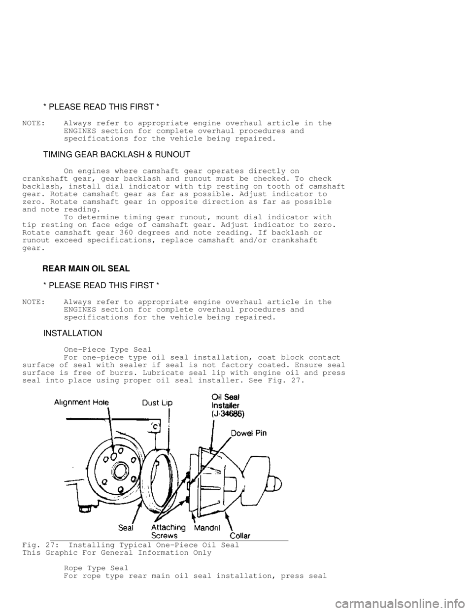
One-Piece Type Seal
For one-piece type oil seal installation, coat block contact
surface of seal with sealer if seal is not factory coated. Ensure seal
surface is free of burrs. Lubricate seal lip with engine oil and press
seal into place using proper oil seal installer. See Fig. 27.
Fig. 27: Installing Typical One-Piece Oil Seal
This Graphic For General Information Only
Rope Type Seal
For rope type rear main oil seal installation, press seal