Page 840 of 1378

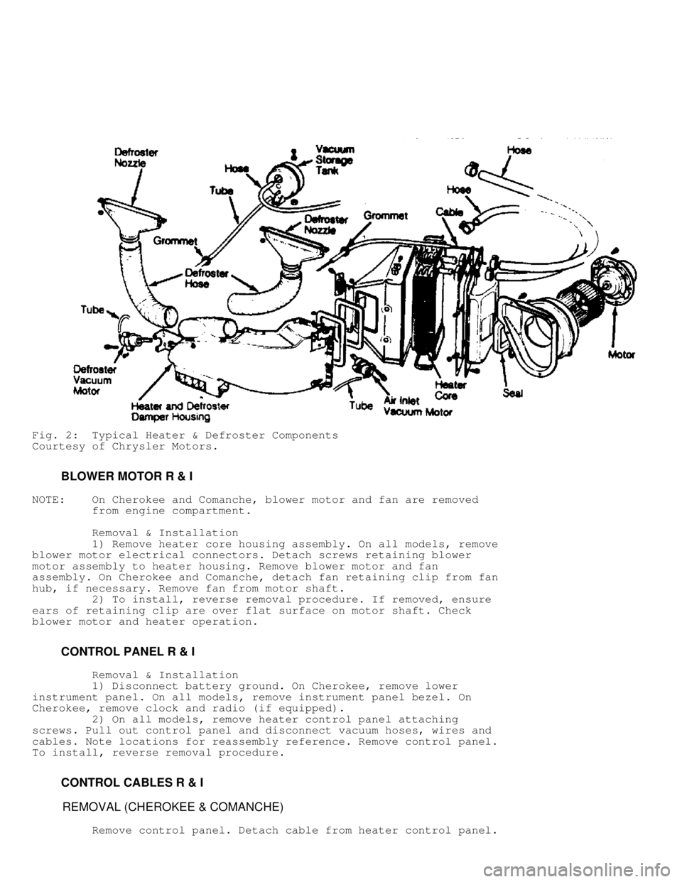
Fig. 2: Typical Heater & Defroster Components
Courtesy of Chrysler Motors.
BLOWER MOTOR R & I
NOTE: On Cherokee and Comanche, blower motor and fan are removed
from engine compartment.
Removal & Installation
1) Remove heater core housing assembly. On all models, remove
blower motor electrical connectors. Detach screws retaining blower
motor assembly to heater housing. Remove blower motor and fan
assembly. On Cherokee and Comanche, detach fan retaining clip from fan
hub, if necessary. Remove fan from motor shaft.
2) To install, reverse removal procedure. If removed, ensure
ears of retaining clip are over flat surface on motor shaft. Check
blower motor and heater operation.
CONTROL PANEL R & I
Removal & Installation
1) Disconnect battery ground. On Cherokee, remove lower
instrument panel. On all models, remove instrument panel bezel. On
Cherokee, remove clock and radio (if equipped).
2) On all models, remove heater control panel attaching
screws. Pull out control panel and disconnect vacuum hoses, wires and
cables. Note locations for reassembly reference. Remove control panel.
To install, reverse removal procedure.
CONTROL CABLES R & I
REMOVAL (CHEROKEE & COMANCHE)
Remove control panel. Detach cable from heater control panel.
Page 845 of 1378

IG NIT IO N S W IT C H & L O CK C YLIN DER
�
1988 J e ep C hero ke e
1988 Ignition Switch & Lock Cylinders
JEEP
DESCRIPTION
The ignition switch and lock cylinder is typically mounted on
the steering column and actuated by an ignition key.
SERVICING
To gain access to ignition components on Jeep vehicles, the
steering column must be removed or lowered and the turn signal switch
must be removed.
CAUTION: The lock plate is held by high spring pressure. DO NOT
remove snap ring without using a compressor tool. If the
steering shaft has standard threads, use Compressor Tool
(J-23653); if the shaft has metric threads use Metric
Forcing Screw (J-23653-4).
CAUTION: Special care must be taken to avoid bumping, jolting or
hammering on the steering shaft and gearshift tube.
REMOVAL & INSTALLATION
LOCK CYLINDER
Removal
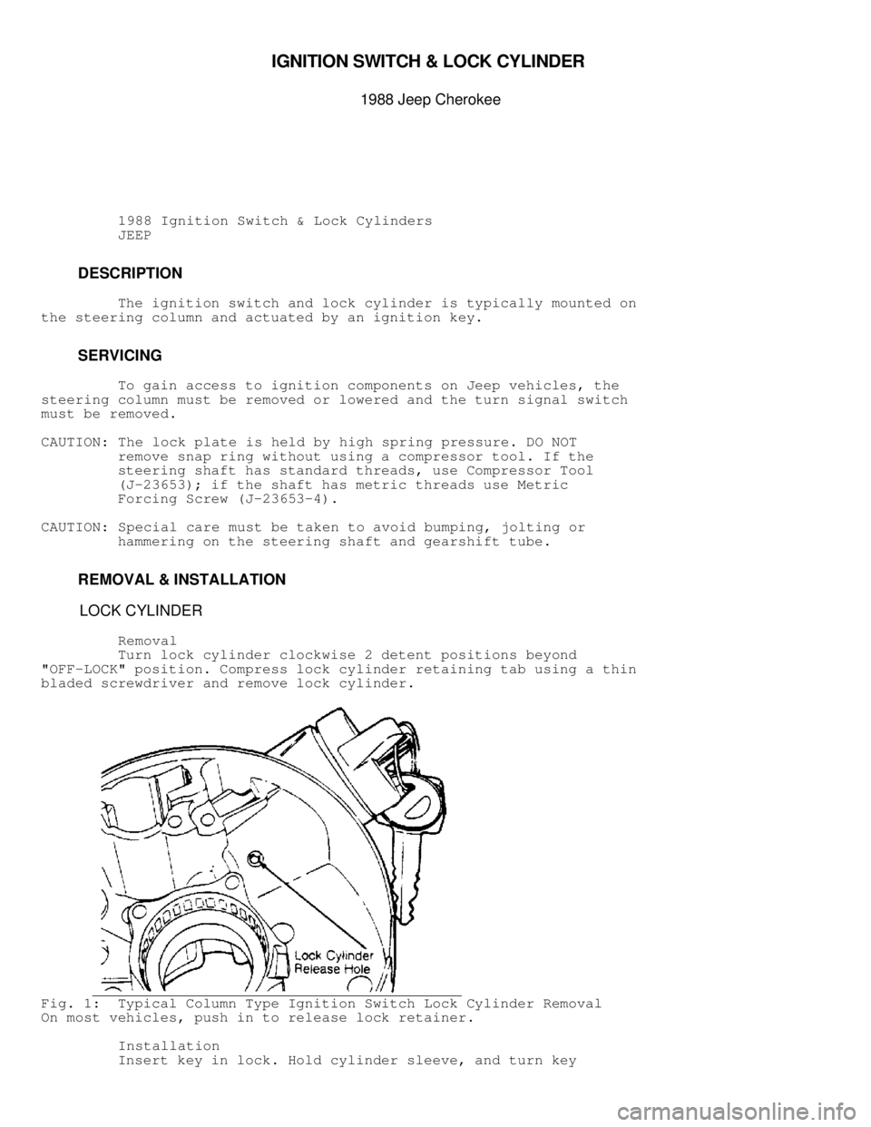
Turn lock cylinder clockwise 2 detent positions beyond
"OFF-LOCK" position. Compress lock cylinder retaining tab using a thin
bladed screwdriver and remove lock cylinder.
Fig. 1: Typical Column Type Ignition Switch Lock Cylinder Removal
On most vehicles, push in to release lock retainer.
Installation
Insert key in lock. Hold cylinder sleeve, and turn key
Page 846 of 1378
clockwise until key stops. Insert cylinder lock into bore with
cylinder tab aligned with keyway in housing. Push cylinder in until it
bottoms. Rotate cylinder counterclockwise to engage lock sector, and
push in until cylinder tab engages in housing groove.
IGNITION SWITCH
Removal
Lower column and remove switch mounting screws. Disconnect
harness connector. Remove switch.
Installation
Move switch slider to "ACC" position. Move switch slider back
2 clicks to "OFF-UNLOCK" position. Insert remote rod in switch slider,
and position switch on column. Do not move slider. Install and tighten
screws.
Fig. 2: Rod-Actuated Ignition Switch
Page 873 of 1378

Removal
1) Disconnect the battery negative cable.
2) On vehicles equipped with A/C, remove the electrical
cooling fan and shroud assembly from the radiator to allow room to
rotate the engine with a socket and ratchet using the vibration damper
bolt.
3) Scribe a mark on the distributor housing below the left
side (past) the number one spark plug wire post of the distributor cap\
for reassembly reference for No 1 cylinder firing position.
4) Remove the distributor cap.
5) Turn the engine in a clockwise direction until the rotor
is approaching the scribed mark on the distributor housing. Then
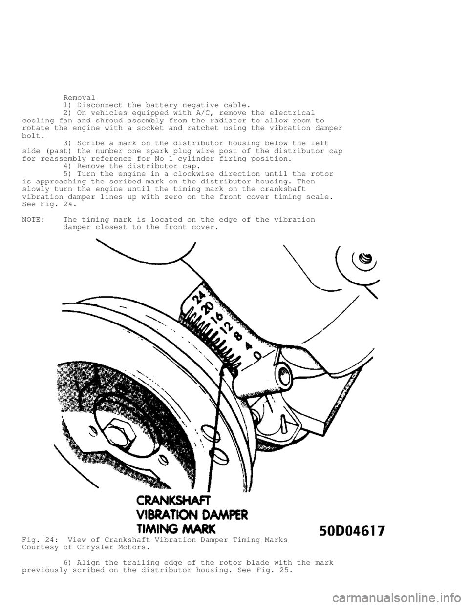
slowly turn the engine until the timing mark on the crankshaft
vibration damper lines up with zero on the front cover timing scale.
See Fig. 24 .
NOTE: The timing mark is located on the edge of the vibration
damper closest to the front cover.
Fig. 24: View of Crankshaft Vibration Damper Timing Marks
Courtesy of Chrysler Motors.
6) Align the trailing edge of the rotor blade with the mark
previously scribed on the distributor housing. See Fig. 25.
Page 875 of 1378
Installation
1) If needed, use a flat blade screwdriver to turn the oil
pump gear shaft until the slot is slightly past the 11 o'clock
position. See Fig. 26. The oil pump shaft is located down in the
distributor hole.
Fig. 26: Aligning Oil Pump Gear Shaft
Courtesy of Chrysler Motors.
2) Install the rotor.
3) Without engaging the distributor gear into the cam gear
and ensuring the distributor gasket is installed, position the
distributor into the hole in the engine block.
4) Visually line up the hold down ear of the distributor
housing with the hold down clamp hole. See Fig. 27.
Fig. 27: Installing Distributor
Courtesy of Chrysler Motors.
5) Turn the rotor to the 4 o'clock position. See Fig. 28.
Page 876 of 1378
Fig. 28: Installing & Aligning Rotor
Courtesy of Chrysler Motors.
6) Carefully slide the distributor into the block until it
seats, keeping the hold down ear aligned to the hole in the block.
7) The rotor should be in the 5 o'clock position with the
trailing edge of the rotor blade lined up with the mark previously
scribed on the distributor housing (number one spark plug wire post
location).
8) install the distributor hold-down clamp bolt and tighten
to 9.5-14 Ft. Lbs. (13-19 N.m).
9) Install the distributor cap. Connect the distributor
electrical connector.
10) Install the electric cooling fan and shroud if
applicable.
11) Connect the negative battery cable.
IGNITION/COIL WIRE REPLACEMENT PRECAUTIONS
Page 920 of 1378
1 - 25 Amp
Rear Washer/Wiper
2 - 15 Amp
Radio, Cigarette Lighter
3 - 25 Amp
Blower Motor
4 - 20 Amp
Turn Signal, Back-Up Lights, Rear Window Defogger Relay
5 - 10 Amp
Dome Light, Courtesy Lights, Glove Box Light, Cargo Light,
Radio Memory, Power Mirrors, Teltak Connector
6 - 15 Amp
Hazard Warning System, Stoplights
7 - 10 Amp
Parking Lights, Headlight Warning Chime/Buzzer, Instrument
Panel Light Dimmer
8 - 7.5 Amp
Gauges, Instrument Cluster, Seat Belt Warning,
Headlight Delay, Chime Module, Overhead Console
9 - 5 Amp
Instrument Panel Illumination
10 - 25 Amp
Rear Window Defogger
11 - 30 Amp (Circuit Breaker)
Power Door Locks, Power Seats, Trailer Towing Wiring Harness
12 - 10 Amp
ETR Radio, Power Antenna
13 - Not Used (1984-87)
7.5 Amp (1988)
Transmission Control Unit
14 - 25 Amp
Headlight Delay, Horns, Security Alarm
15 - 5.5 Amp (Circuit Breaker)
Front Wiper
16 - 30 Amp (Circuit Breaker)
Power Windows
17 - 10 Amp
Clock, Security Alarm (IGN)
Page 1014 of 1378

\003
STA R TE R - B O SC H/M IT S U BIS H I
�
1 988 J e ep C hero ke e
1988 Starters
BOSCH & MITSUBISHI
Jeep with 4.0L 6-Cyl.
DESCRIPTION
NOTE: Information on Jeep 2.5L starter not available from
manufacturer.
Bosch and Mitsubishi use a permanent magnet starter. A
planetary gear train transmits power between starter motor and pinion
shaft. The starter magnetic field is produced by 6 permanent magnets.
The Mitsubishi starter is a 12-volt unit that has the solenoid mounted
on the starter housing. See Fig. 3.
TROUBLE SHOOTING
NOTE: See the TROUBLE SHOOTING - BASIC PROCEDURES article
in the GENERAL TROUBLE SHOOTING section.
TESTING (ON VEHICLE)
AMPERAGE DRAW TEST
NOTE: Engine should be at operating temperature before performing
this test. Heavy duty oil or a tight engine will increase
starter draw amperage. Tests are performed with standard
volt-ammeter tester.
1) Connect tester and remote starter switch. Set voltmeter
selector to 16-volt position. Select function to 0-500-amp scale.
Connect voltmeter leads to corresponding polarity battery terminals.
2) Connect ammeter leads to corresponding battery terminals.
Disconnect coil wire from distributor cap and attach to ground to
prevent engine from starting.
3) Crank engine and observe exact reading on voltmeter. Stop
cranking engine. Turn tester control knob clockwise until voltmeter
reads exactly the same as when engine was cranked with remote starter
switch. Ammeter should indicate starter draw of about 150-220 amps.
STARTER RESISTANCE TEST
Use a voltmeter that will indicate tenths of a volt. Without
disconnecting any starter connections, perform the following
resistance tests:
1) Perform following tests with engine cranking and all
terminals connected. Connect a voltmeter at following locations:
* Positive lead to battery positive post and negative lead
to battery terminal on starter.
* Positive lead to starter housing and negative lead to
negative post on battery.
* Positive lead to battery negative post and negative lead
to battery cable connector on engine block.
2) Each of these 3 connections should show a voltmeter