1988 FIAT TEMPRA sensor
[x] Cancel search: sensorPage 91 of 171
Q Step 2: Before starting the engine, make sure all your
electrical connections are sound and your fuel, oil and coolant
connections are correct and secure.
Q Step 3: Run the engine to working temperature and then
allow to cool. Re-check all fluid levels.
Job 20. Diesel engine.
Mountings - replacement.
See
Job
12
and Job
18,
Step 20
Job 21. Diesel engine/
transmission (removed from car)
- separation.
Q Step 1: Remove the starter motor.
• Step 2: On the turbo version, undo the flange bolts see
Job
18,
Step 16A and withdraw the drive-shaft extension, if
still
fitted.
Q Step 3: Unbolt and remove the rear engine plate and the
gearbox, being careful to support the gearbox weight as it is
withdrawn.
Job 22. Diesel engine/
transmission (removed from car)
- reconnection.
Q Step 1: Before proceeding, check the condition of the
clutch and
its release mechanism. Make sure the driven plate
is
properly centred on the flywheel
-
see PART B: TRANS-
MISSION.
Q Step 2: Now reverse the order of separation, but be
careful when
engaging the gearbox input shaft with the
clutch
driven plate that you don't 'hang' its weight on the
splines.
Also,
see
Job 11.
Job 23. Diesel engine -
dismantling.
This Job should
be read in conjunction with Job 5 The
engines are
broadly similar although the information given in
this Job takes
priority for diesel engines. It is MOST
IMPORTANT that you read the FACT FILE on page 84.
SAFETY FIRST!
•
The inside
of diesel engines are particularly filthy
places!
•
Old diesel
oil
is
carcinogenic!
•
Wear suitable
impervious gloves!
I
• Step 1: Remove the timing belt and cylinder head. See
Jobs
13
and 14.
Q Step 2: Remove the alternator, water pump and
thermostat housing distribution pipe.
• Step 3: Remove the crankshaft timing belt sprocket.
Q INSIDE INFORMATION! Note that the bolt securing
the crankshaft sprocket has a left-hand thread and must
be undone clockwise. D
• Step 4: Unbolt the timing belt tensioner and idler pulleys.
• Step 5: Remove the injection pump sprocket.
Q INSIDE INFORMATION! You will need two FIAT tools
for this operation. One (No. 1860473000) is to prevent
the sprocket from turning when undoing the nut, and
the other (extractor No. 1842128000) to pull the sprocket
from the injection pump shaft. Alternatively it may be
possible to improvise a means of preventing sprocket
rotation, and a suitable three-leg puller may be carefully
used to withdraw the sprocket. Take care not to lose the
pump shaft Woodruff key. B
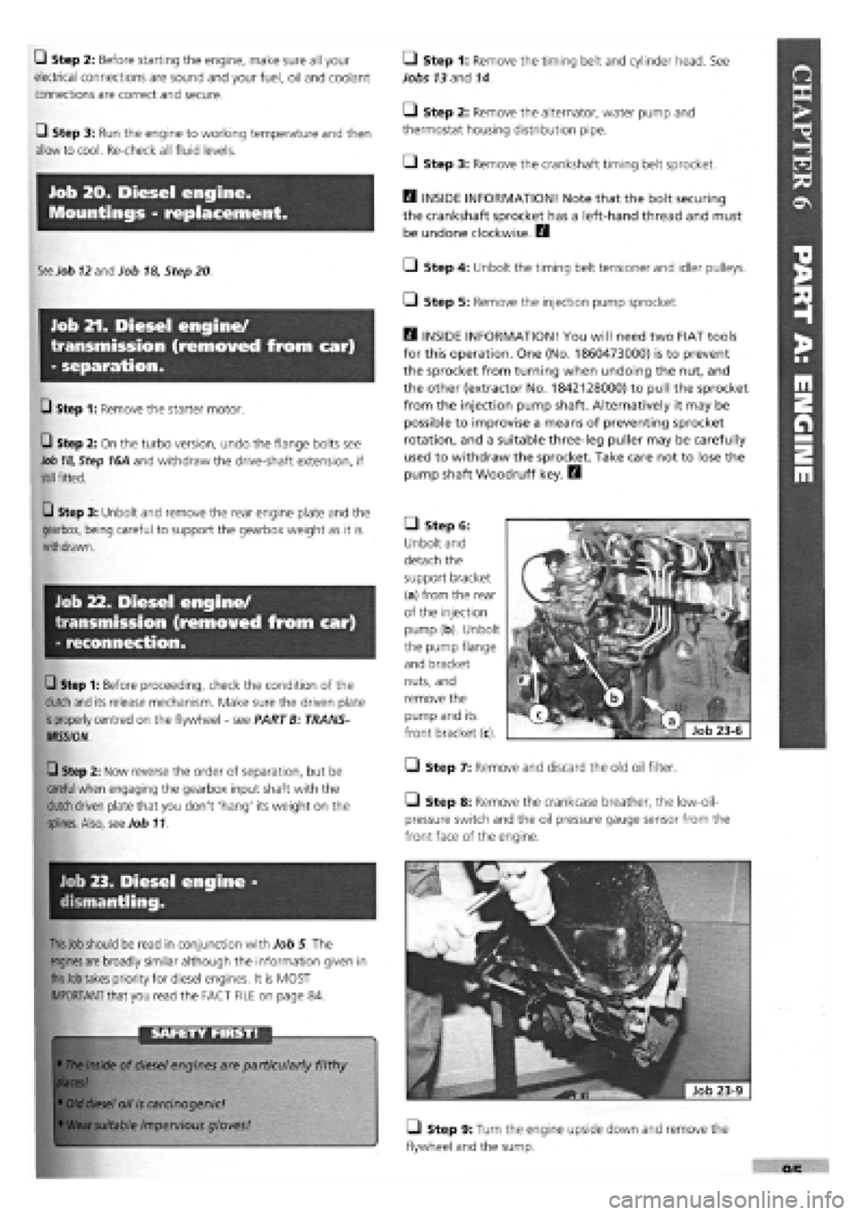
• Step 6:
Unbolt and
detach the
support bracket
(a) from the rear
of the injection
pump (b). Unbolt
the pump flange
and bracket
nuts, and
remove the
pump and its
front bracket (c).
• Step 7: Remove and discard the old oil filter.
Step 8: Remove the crankcase breather, the low-oil-
pressure switch and the oil pressure gauge sensor from the
front face of the engine.
• Step 9: Turn the engine upside down and remove the
flywheel and the sump.
Page 105 of 171
SAFETY FIRST!
Step 1: Take note of the location and identification of the
main
components:
Q Step 2: Before starting to remove the unit, unplug all of
the
distributor cap
HT
leads.
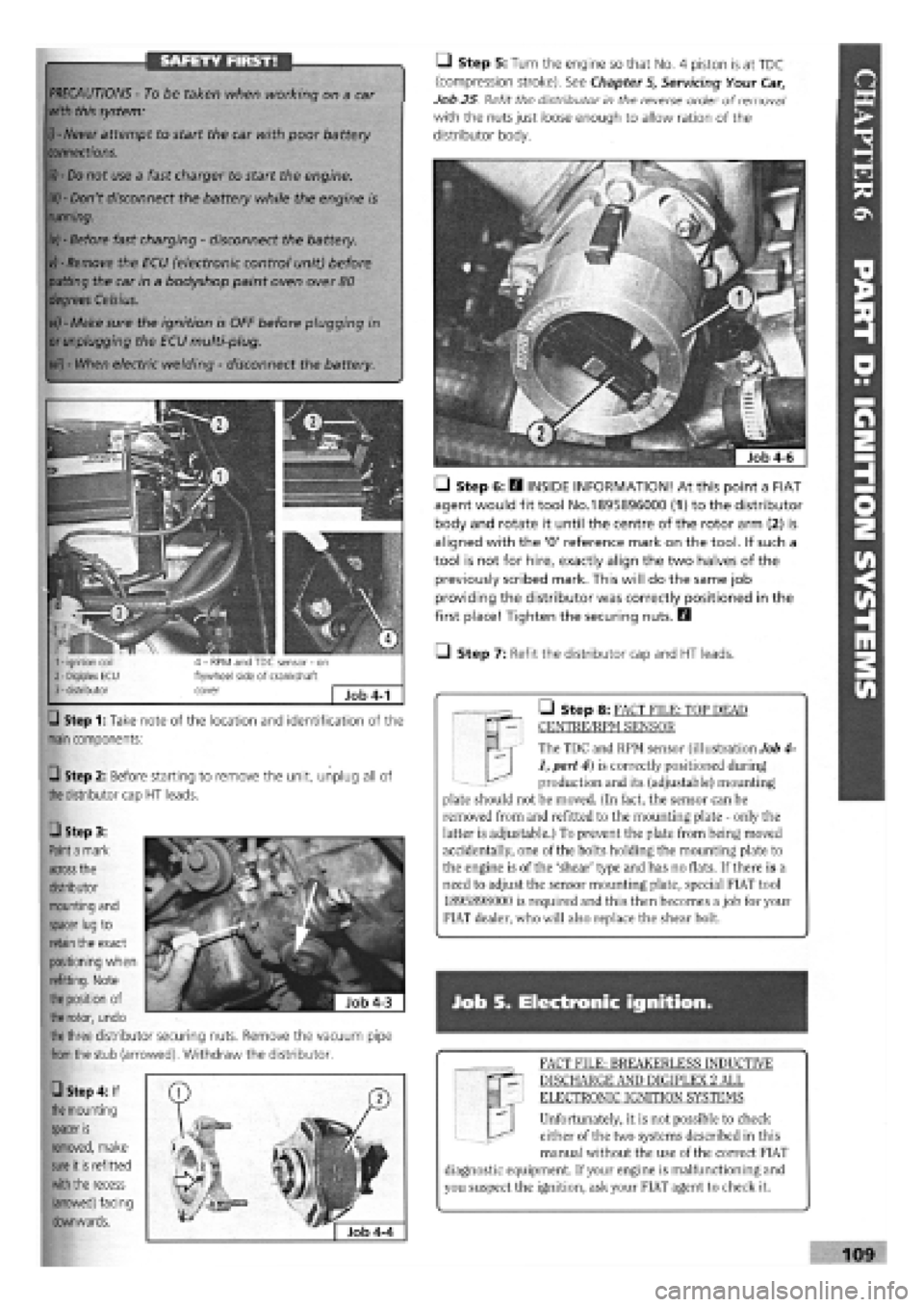
M | The TDC and RPM sensor (illustration Job 4-
1, part 4) is correctly positioned during
production and its (adjustable) mounting
plate should not be moved. (In fact, the sensor can be
removed from and refitted to the mounting plate - only the
latter is adjustable.) To prevent the plate from being moved
accidentally, one of the bolts holding the mounting plate to
the engine is of the 'shear' type and has no flats. If there is a
need to adjust the sensor mounting plate, special FIAT tool
1895898000 is required and this then becomes a job for your
FIAT dealer, who will also replace the shear bolt.
• Step 8: FACT FILE: TOP DEAD
CENTRE/RPM SENSOR
PRECAUTIONS -
To be taken when working on a car
with this system:
i) - Never
attempt to start the car with poor battery
connections.
ii) - Do
not use a fast charger to start the engine.
iii) -
Don't disconnect the battery while the engine is
running.
iv) -
Before fast charging
-
disconnect the battery.
vj - Remove
the ECU (electronic control unit) before
putting
the car in a bodyshop paint oven over
80
degrees Celsius.
vi) -
Make sure the ignition is OFF before plugging in
or unplugging
the ECU multi-plug.
vii) -
When electric welding
-
disconnect the battery.
Q Step 5: Turn the engine so that No. 4 piston is at TDC
(compression stroke). See Chapter
5,
Servicing Your Car,
Job 25 Refit the distributor in the reverse order of removal1
with the nuts just loose enough to allow ration of the
distributor body.
• Step 6: E3 INSIDE INFORMATION! At this point a FIAT
agent would fit tool No.1895896000 (1) to the distributor
body and rotate it until the centre of the rotor arm (2) is
aligned with the '0' reference mark on the tool. If such a
tool is not for hire, exactly align the two halves of the
previously scribed mark. This will do the same job
providing the distributor was correctly positioned in the
first place! Tighten the securing nuts. Q
• Step 7: Refit the distributor cap and HT leads.
Job S. Electronic ignition.
FACT FILE: BREAKERLESS INDUCTIVE
DISCHARGE AND DIGIPLEX 2 ALL
ELECTRONIC IGNITION SYSTEMS
Unfortunately, it is not possible to check
either of the two systems described in this
manual without the use of the correct FIAT
diagnostic equipment. If your engine is malfunctioning and
you suspect the ignition, ask your FIAT agent to check it.
109
• Step 3:
Paint a
mark
across
the
distributor
mounting and
spacer lug
to
retain
the exact
positioning when
refitting. Note
the position
of
the rotor,
undo
the three
distributor securing nuts. Remove the vacuum pipe
from the
stub (arrowed). Withdraw the distributor.
• Step 4: If
the
mounting
spacer
is
removed, make
sure
it
is
refitted
with the
recess
(arrowed) facing
downwards.
Page 112 of 171

PART F: FUEL AMD EXHAUST SYSTEMS
PART F: Contents
Job 1. Fuel system types. Job 9. Electric fuel pump, petrol engine (S.P.I.)
-
Job 2. Carburettor
-
removal and refitting. replacement.
Job 3. Petrol injection unit
-
removal and refitting. Job 10. Fuel tank
-
removal and refitting.
Job 4. Accelerator cable, carburettor engines
-
replacement Job 11. Hot air hoses/thermo-valves
-
general.
and adjustment. Job 12. Lambda sensor (S.P.I, engines)
-
replacement.
Job 5. Carburettor choke cable
-
replacement and Job 13. Fuel evaporation system.
adjustment. Job 14. Exhaust system
-
replacement.
Job 6. Accelerator cable, petrol injection engines -Job 15. Turbocharger, diesel engine
-
replacement.
replacement and adjustment. Job 16. Diesel injection pump
-
removal and refitting.
Job 7. Diesel engines. Accelerator cable
-
replacement and Job 17. Diesel injectors
-
remove and refit.
adjustment. Job 18. Bleeding Diesel fuel system.
Job 8. Mechanical fuel pump, petrol engine (carburettored) -
replacement.
Job 1. Fuel system types.
FACT FILE: FUEL INJECTION/ELECTRONIC
IGNITION PRECAUTIONS
OBSERVE THE FOLLOWING PRECAUTIONS
WHEN WORKING ON PETROL-ENGINED
VEHICLES WITH FUEL INJECTION - ELECTRONIC
IGNITION SYSTEMS:
• never start the engine when the electrical terminals are
poorly connected or loose on the battery poles;
• never use a quick battery charger to start the engine;
• never disconnect the battery from the car circuit with the
engine running;
• when charging the battery quickly, first disconnect the
battery from the vehicle circuit;
• if the vehicle is placed in a bodyshop drying oven after
painting at a temperature of more than 80 degrees Celsius,
first remove the injection/ignition ECU;
• never connect or disconnect the ECU multiple connector
with the ignition key in MARCIA position;
• always disconnect battery negative lead before carrying out
electrical welding on vehicle.
Note that some systems contain one memory that is always
active (stand-by memory) and that stores learnt self-adaptive
values. Because this data is lost when the battery is discon-
nected, this operation should be carried out as infrequently as
possible.
Refer to illustrations in Job 1 for typical layouts.
It's a good idea to familiarise yourself with the type of fuel
system fitted to your car. These are the main types.
• Type 1: This is the 1400/1600cc carburettored engines
fuel system.
SAFETY FIRST!
• The high pressure pipework on a petrol or diesel fuel
injection system can retain its pressure for days even
after the engine has been switched off.
• When you disconnect the pipework, a jet of fuel can
be emitted under very high pressure
-
strong enough to
penetrate the skin or damage the eyes.
• NEVER work on the fuel pipework when the engine is
running (except when bleeding Diesel injectors
-
see Job
18.
• ALWAYS place a rag over a union while it is being
undone until all the pressure has been let out of the
system.
• You must wear strong rubber gloves and goggles
when disconnecting the fuel injection system's high
pressure pipework. Always disconnect VERY slowly,
letting pressure out progressively.
• See Job 8 for details of how to depressurise the
system.
• Disconnect the battery negative earth before working
on the fuel system.
• Work outdoors and away from sources of flame or
ignition.
• ALWAYS wear rubber gloves
-
don't let your skin come
into contact with fuel.
1 - overflow pipe 2 - safety valve/roll over cut-off device 3 - fuel tank 4 - carburettor 5 - fuel supply, pump to carburettor 6 - mechanical fuel pump
7 - fuel filter 8 - fuel supply, tank to pump 9 - excess fuel return, carburettor to tank 10 - breather pipe, between highest and lowest Job
1-1
Page 114 of 171
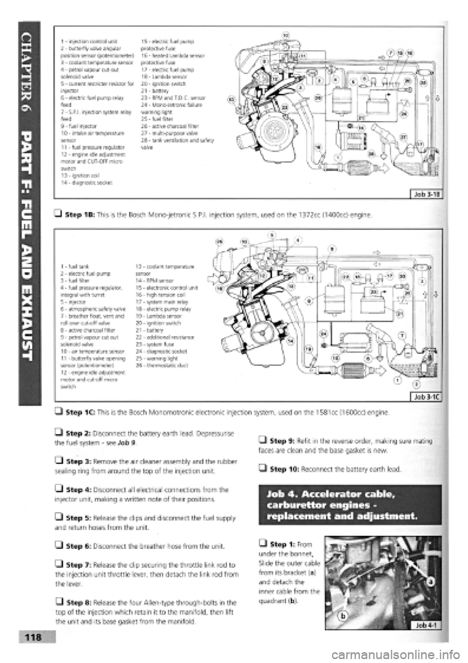
1 - injection control unit 15 - electric fuel pump 2 - butterfly valve angular protective fuse position sensor (potentiometer) 16 - heated Lambda sensor 3 - coolant temperature sensor protective fuse 4 - petrol vapour cut-out 17 - electric fuel pump solenoid valve 18 - Lambda sensor 5 - current restricter resistor for 20 - ignition switch injector 21 - battery 6 - electric fuel pump relay 23 - RPM and T.D.C. sensor feed 24 - Mono-Jetronic failure 7 - S.P.I, injection system relay warning light feed 25
-
fuel filter 9 - fuel injector 26 - active charcoal filter 10 - intake air temperature 27 - multi-purpose valve sensor 28 - tank ventilation and safety 11 - fuel pressure regulator valve 12 - engine idle adjustment motor and CUT-OFF micro switch 13 - ignition coil 14 - diagnostic socket
Q Step 1B: This is the Bosch Mono-jetronic S.P.I, injection system, used on the 1372cc (1400cc) engine.
1 - fuel tank 13 coolant temperature 2 - electric fuel pump sensor 3 - fuel filter 14 RPM sensor 4 - fuel pressure regulator, 15 electronic control unit integral with turret 16 - high tension coil 5 - injector 17 - system main relay 6 - atmospheric safety valve 18 - electric pump relay 7 - breather float, vent and 19 - Lambda sensor roll over cut-off valve 20 - ignition switch 8 - active charcoal filter 21 - battery 9 - petrol vapour cut out 22 - additional resistance solenoid valve 23 - system fuse 10 - air temperature sensor 24 - diagnostic socket 11 - butterfly valve opening 25 - warning light sensor (potentiometer) 26 - thermostatic duct 12 - engine idle adjustment motor and cut-off micro switch
Q Step 1C: This is the Bosch Monomotronic electronic injection system, used on the
1581
cc (1600cc) engine.
• Step 2: Disconnect the battery earth lead. Depressurise
the fuel system
-
see Job 9.
• Step 3: Remove the air cleaner assembly and the rubber
sealing ring from around the top of the injection unit.
Q Step 4: Disconnect all electrical connections from the
injector unit, making a written note of their positions.
Q Step 5: Release the clips and disconnect the fuel supply
and return hoses from the unit.
G Step 6: Disconnect the breather hose from the unit.
• Step 7: Release the clip securing the throttle link rod to
the injection unit throttle lever, then detach the link rod from
the lever.
Q Step 8: Release the four Allen-type through-bolts in the
top of the injection which retain it to the manifold, then lift
the unit and its base gasket from the manifold.
• Step 9: Refit in the reverse order, making sure mating
faces are clean and the base gasket is new.
• Step 10: Reconnect the battery earth lead.
Job 4. Accelerator cable,
carburettor engines -
replacement and adjustment.
• Step 1: From
under the bonnet,
Slide the outer cable
from its bracket (a)
and detach the
inner cable from the
quadrant (b).
118
Page 116 of 171
over stop and will also reach its 'maximum speed' stop with
the pedal fully depressed.
Job 8. Mechanical fuel pump,
petrol engine (carburettored) -
replacement.
O Step 1: Disconnect the battery earth lead.
• Step 2: Find the pump on the forward facing side of the
cylinder block near the timing cover end. Disconnect the two
fuel lines from the pump and plug the ends, (labelling them
for correct refitment).
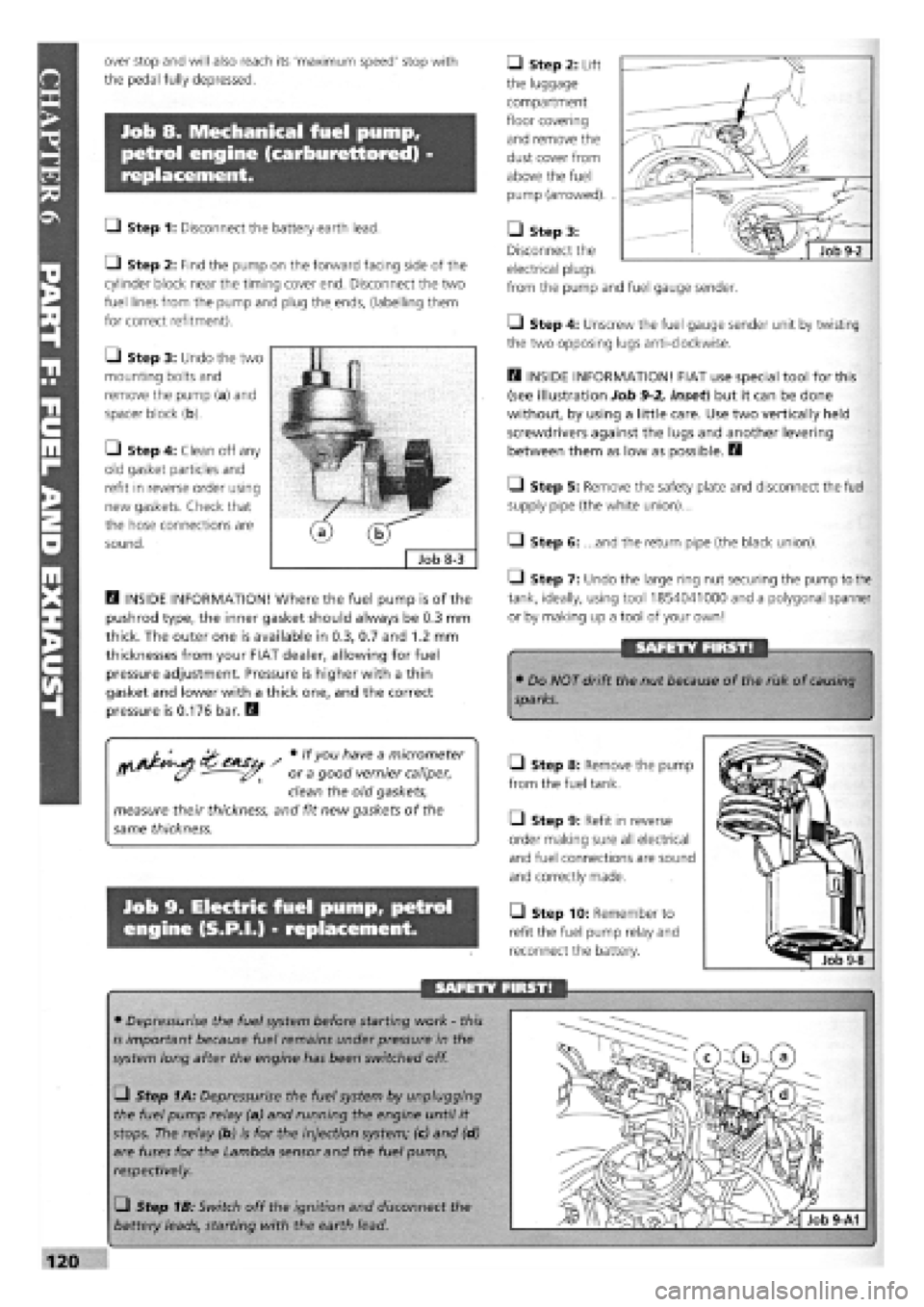
• Step 3: Undo the two
mounting bolts and
remove the pump (a) and
spacer block (b).
• Step 4: Clean off any
old gasket particles and
refit in reverse order using
new gaskets. Check that
the hose connections are
sound.
D INSIDE INFORMATION! Where the fuel pump is of the
pushrod type, the inner gasket should always be 0.3 mm
thick. The outer one is available in 0.3, 0.7 and 1.2 mm
thicknesses from your FIAT dealer, allowing for fuel
pressure adjustment. Pressure is higher with a thin
gasket and lower with a thick one, and the correct
pressure is 0.176 bar. Q
/ # lfyou h"ve a m/cromefer
ff (y - or a good vernier caliper,
clean the old gaskets,
measure their thickness, and fit new gaskets of the
same thickness.
Job 9. Electric fuel pump, petrol
engine (S.P.I.) - replacement.
• Step 2: Lift
the luggage
compartment
floor covering
and remove the
dust cover from
above the fuel
pump (arrowed). .
• Step 3:
Disconnect the
electrical plugs
from the pump and fuel gauge sender.
• Step 4: Unscrew the fuel gauge sender unit by twisting
the two opposing lugs anti-clockwise.
D INSIDE INFORMATION! FIAT use special tool for this
(see illustration Job
9-2,
inset) but it can be done
without, by using a little care. Use two vertically held
screwdrivers against the lugs and another levering
between them as low as possible. H
Q Step 5: Remove the safety plate and disconnect the fuel
supply pipe (the white union)...
Q Step 6: ...and the return pipe (the black union).
1-1 Step 7: Undo the large ring nut securing the pump to the
tank, ideally, using tool 1854041000 and a polygonal spanner
or by making up a tool of your own!
SAFETY FIRST!
• Do NOT drift the nut because of the risk of
causing
sparks.
Q Step 8: Remove the pump
from the fuel tank.
Q Step 9: Refit in reverse
order making sure all electrical
and fuel connections are sound
and correctly made.
• Step 10: Remember to
refit the fuel pump relay and
reconnect the battery.
SAFETY FIRST!
• Depressurise the fuel system before starting work
-
this
is important because fuel remains under pressure in the
system long after the engine has been switched off.
• Step 1A: Depressurise the fuel system by unplugging
the fuel pump relay (a) and running the engine until it
stops. The relay (b) is for the injection system; (c) and (d)
are fuses for the Lambda sensor and the fuel pump,
respectively.
• Step 1B: Switch off the ignition and disconnect the
battery leads, starting with the earth lead.
Page 117 of 171

Job 10. Fuel tank - removal and
refitting.
Job 11. Hot air hoses/thermo-
valves - general.
SAFETY FIRST!
Job 12. Lambda sensor
(S.P.I, engines) - replacement.
• We recommend that you carry out all of this work
out of
doors.
I
IMPORTANT NOTE:
• Read Chapter 1, Safety First! before carrying out
this
work!
• Plan ahead! Run the fuel in the tank as low as possible
before you start this job.
Q Step 1: Disconnect the battery leads starting with the
earth lead.
• Step 2: Syphon any remaining fuel from the tank and
into a suitable closed container.
Q Step 3: Disconnect the fuel sender wiring and any fuel
hoses
from within the boot (model-dependent
-
see Job 9 and
PARTE: ELECTRICAL AND INSTRUMENTS, Job 14).
• Step 4: Disconnect the filler and breather hoses from the
tank,
working from underneath the car.
a - Lambda sensor b - connector to ECU c - sensor heater power supply Job 12-2
Q Step 5: Support the tank while undoing the strap
securing bolts at the rear of the tank...
Q Step 6: ...and at the front.
Q Step 7: Lower the tank a very small amount at a time,
enough to check whether any hoses remain attached, then
lower it fully to the ground.
Q Step 8: Refit in the reverse order, making sure all connec-
tions are
sound. Reconnect the battery leads.
• Step 1: H INSIDE INFORMATION: The good
operation of the thermostatic valve in the air cleaner
where the heated air pipe from the manifold enters the
air filter) relies on air hoses that are in good condition.
Replace any that are doubtful before suspecting the
valve to be faulty. These valves usually give little trouble
and usually only suffer from sticking, caused by dirt.
Try cleaning the flap and hinge before assuming the
worst! Q
• Step 1: The Lambda sensor
can be found screwed into the
exhaust just behind the point
where the down pipes run into
one (arrowed).
Q Step 2: Trace the wiring
back from the sensor and
disconnect the two plugs,
(b and c).
a - air filter b - injection unit c - inlet manifold d - cool air intake e - heated air intake - from exhaust manifold f
-
thermostatic valve flap g - thermostatic valve
Job 11-1
Page 118 of 171
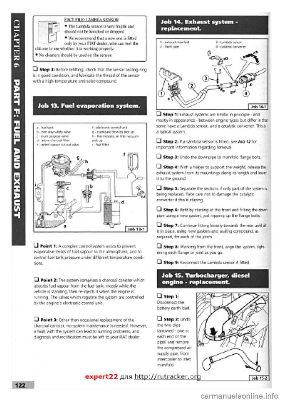
Job 14. Exhaust system -
replacement.
FACT FILE: LAMBDA SENSOR
• The Lambda sensor is very fragile and
should not be knocked or dropped.
• We recommend that a new one is fitted
only by your FIAT dealer, who can test the
old one to see whether it is working properly.
• No cleaners should be used on the sensor.
Q Step 3: Before refitting, check that the sensor sealing ring
is in good condition, and lubricate the thread of the sensor
with a high-temperature anti-seize compound.
Job 13. Fuel evaporation system.
a - fuel tank b - two way safety valve c - multi purpose valve d
-
active charcoal filter e - petrol vapour cut out valve
f - electronic control unit g - crankcase blow by pick up h - thermostatic air filter vacuum pick up i - fuel filter
• Point 1: A complex control system exists to prevent
evaporative losses of fuel vapour to the atmosphere, and to
control fuel tank pressure under different temperature condi-
tions.
—) Step 1: Exhaust systems are similar in principle
-
and
mostly in appearance
-
between engine types but differ in that
some have a Lambda sensor, and a catalytic converter. This is
a typical system.
• Step 2: If a Lambda sensor is fitted, see Job
12
for
important information regarding removal.
• Step 3: Undo the downpipe to manifold flange bolts.
• Step 4: With a helper to support the weight, release the
exhaust system from its mountings along its length and lower
it to the ground.
O Step 5: Separate the sections if only part of the system is
being replaced. Take care not to damage the catalytic
converter if this is staying.
• Step 6: Refit by starting at the front and fitting the down
pipe using a new gasket, just nipping up the flange bolts.
• Step 7: Continue fitting loosely towards the rear until all
is in place, using new gaskets and sealing compound, as
required, for each of the joints.
• Step 8: Working from the front, align the system, tight-
ening each flange or joint as you go.
• Step 9: Reconnect the Lambda sensor if fitted.
• Point 2: The system comprises a charcoal canister which
absorbs fuel vapour from the fuel tank, mostly while the
vehicle is standing, then re-injects it when the engine is
running. The valves which regulate the system are controlled
by the engine's electronic control unit.
• Point 3: Other than occasional replacement of the
charcoal canister, no system maintenance is needed. However,
a fault with the system can lead to running problems, and
diagnosis and rectification must be left to your FIAT dealer.
Job 15. Tlurbocharger, diesel
engine - replacement.
• Step 1:
Disconnect the
battery earth lead.
• Step 2: Undo
the two clips
(arrowed
-
one at
each end of the
pipe) and remove
the compressed air
supply pipe, from
intercooler to inlet
manifold.
expert22 fl/i* http://rutracker.or
Page 130 of 171

• Step 8:
Support the
axle beam with
the jack and
undo the
mounting bolts
(arrowed and
indicated by
operator with
socket bar).
Lower the
complete unit
from the car.
IMPORTANT NOTE: In this shot, the top shock absorber
mountings have been disconnected, leaving the shock
absorber fitted to the suspension and the coil springs in
place. We recommend 'our' approach, covered in Step 7!
• Step 9: Undo the bolts securing the anti-roll bar and
remove it. (See Job 9.) Disconnect the brake pipes from the
side to be worked on and remove the brake drum.
Q Step 10: Remove the hub cap (see illustration Job 1-1D,
part 13) by carefully tapping and levering with a screwdriver.
• Step 11: Undo the hub nut (see illustration Job 1-1D,
part
10).
PART H: BRAKES
• Step 12: A special tool
(1857508000) or a VERY
strong Allen key (a) will be
required to reach into the
hub (b), and plenty of
leverage!
Q Step 13: Remove the
hub and inspect the bearing
for roughness or noise or
roughness when turning it by hand.
E3 INSIDE INFORMATION! The bearing is lubricated for
life and is only supplied as an assembly with the hub. B
• Step 14: Inspect the stub axle pin (see illustration Job
1-
1D, part
12)
for any signs of damage or distortion. Replace if
in doubt.
Q Step 15: Refitting is the reverse of removal but note the
following:
• See Chapter
3,
Facts and Figures for all tightening
torques as you progress through the assembling.
• Use new hub nuts and fully tighten once the suspension is
mounted to give you stability.
• Refer to PART H: BRAKES when refitting the brake parts
and bleeding the brakes.
PART H: Contents %
Job 1. Understanding Tipo/Tempra brakes.
Job 2. Front brake pads
-
replacement.
Job 3. Front brake caliper
-
replacement.
Job 4. Front brake disc
-
replacement.
Job 5. Rear brake shoes
-
replacement.
Job 6. Rear wheel cylinder
-
replacement.
Job 7. Rear brake disc pads
-
replacement.
Job 8. Rear brake caliper
-
replacement.
Job 9. Rear brake disc
-
replacement.
Job 10. Master cylinder
-
replacement.
Job 11. Servo check
-
remove and refit.
Job 12. Pressure regulating valve, non-ABS system -
replacement and adjustment.
Job 13. Pressure regulating valves, ABS system
-
replacement
and adjustment.
Job 14. RPM sensors, ABS systems
-
replacement.
Job 15. Flexible hoses
-
replacement.
Job 16. Metal pipes
-
replacement.
Job 17. Brake bleeding.
Job 18. Handbrake cables
-
replacement.
Job 1. Understanding
Tipo/Tempra brakes.
• Point
1
A: This is the standard disc/drum system used on
cars without anti-lock brakes, shown here in left hand drive
form.
1 - fluid reservoir and master cylinder 2 - servo 3
-
front disc brakes
4 - handbrake lever 5 - rear drum brakes 6
-
four way pipe union 7 - load proportioning/ pressure limiting valve
Job 1-1A
1 - front disc brakes 2
-
front flywheel 3 - front wheel RPM sensors 4 - hydraulic control unit 5 - brake light switch 6 - device failure warning light switch
7 - rear flywheel 8 - main control relay with excess voltage protection 9 - electronic control unit 10 - rear disc brakes 11 - rear wheel RPM sensors 12 - load proportioning/pressure limiting valve Job
1-1B