1988 FIAT TEMPRA change wheel
[x] Cancel search: change wheelPage 75 of 171
G Step 43: Stop the engine and allow it to cool, check the
oil
and coolant levels and look for any leaks.
G Step 44: Avoid over-rewing or overloading the engine
during its settling down period of 600 miles. We recommend
an oil
and filter change at this mileage
-
this will help to
extend the life of your new engine.
Job 7. Petrol engine.
Valve clearances - adjustment.
0 INSIDE INFORMATION! Adjustment should always be
made with the engine cold. B
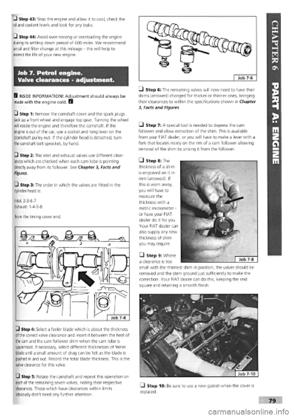
G Step 1: Remove the camshaft cover and the spark plugs.
Jack up a front wheel and engage top gear. Turning the wheel
will rotate the engine and therefore the camshaft. If the
engine
is
out of the car, use a socket and long lever on the
crankshaft pulley nut. If the cylinder head is detached, turn
the
camshaft belt sprocket, by hand.
G Step 2: The inlet and exhaust valves use different clear-
ances
which are checked when each cam lobe is pointing
directly away from its follower. See Chapter
3,
Facts and
Figures.
G Step 3: The order in which the valves are fitted in the
cylinder head is:
Inlet: 2-3-6-7
Exhaust: 1-4-5-8
from
the timing cover end.
G Step 4: Select a feeler blade which is about the thickness
of the
correct valve clearance and insert it between the heel of
the cam
and the cam follower shim when the cam lobe is
uppermost. If necessary, select different thicknesses of feeler
blade until a small amount of drag can be felt as the blade is
pushed in and out. Record the total blade thickness. This is the
valve clearance for this valve.
G Step 5: Rotate the camshaft and repeat this operation on
each
of the remaining seven valves, noting their respective
clearances. Those which have clearances within limits
obviously don't need any further attention.
Q Step 6: The remaining valves will now need to have their
shims (arrowed) changed for thicker or thinner ones, bringing
their clearances to within the specifications shown in Chapter
3, Facts and Figures
Ll Step 7: A special tool is needed to depress the cam
follower and allow extraction of the shim. This is available
from your FIAT dealer, or you will have to make a lever with a
fork that locates nicely on the rim of a cam follower allowing
removal of the shim by prising it from the follower.
• Step 8: The
thickness of a shim
is engraved on it in
mm (arrowed). If
this is worn away,
you will have to
measure the
thickness with a
metric micrometer
-
or have your FIAT
dealer do it for you.
Your FIAT dealer can
also supply any new
thickness of shim
you may require.
• Step 9: Where
a clearance is too
small with the thinnest shim in position, the valves should be
removed and the stem ground just sufficiently to make the
correction. Your FIAT dealer can do this, keeping the end
square and retaining a smooth finish.
fjfefe^ | Job 7-10
Q Step 10: Be sure to use a new gasket when the cover is
replaced.
Page 79 of 171

Job 10. Petrol engine/
transmission (removed from car)
- separation.
Job 11. Petrol engine/
transmission (removed from car)
- reconnection.
• Clean the whole unit
with a proprietary
degreaser
-
and dry off
before
starting work.
•
This
makes these heavy components easier and safer
to
handle
and greatly reduces the risk of contami-
nation
when you strip them down.
Job 10-1
Q Step 1: Undo and remove the transmission mounting
bracket (b),
the starter motor (d) and unbolt and remove the
pressed
steel cover plate (a) from the lower face of the
flywheel housing. Undo the flywheel housing connecting bolts
and note
the position of the engine and transmission
mounting brackets and lifting eyes. The engine mounting arm
can be
left in place but the mounting itself (c) can now be
removed, if required.
Q Step 2: Support the weight of the transmission so that it
doesn't 'hang' on the clutch and withdraw it from the engine
in a
straight line.
Refer to Job
10
for the location of components referred to
here.
• Step 1: Offer the transmission to the engine. The input
shaft should slide easily through the splined hub of the driven
plate, provided that it is still centralised. See PART B:
TRANSMISSION Re-centre the clutch if necessary.
r ' «the input shaft and
- hub splines are not aligned,
ask a helper to turn the
crankshaft pulley nut while you apply gentle pressure
to bring the two units together.
• Step 2: Once the input shaft is properly engaged, use
two bolts, tightened evenly, to draw the units together.
DON'T force it! If the units don't come together easily,
separate them, check clutch centring and try again. Fit the
remaining bolts, not forgetting the lifting eyes and brackets.
• Step 3: Refit the flywheel housing cover plate and
mounting bracket.
Q Step 4: Refit the starter motor.
Job 12. Petrol engine.
Mountings - replacement.
See Job 8, Steps 21 to 23 for details of engine and trans-
mission mounting positions.
Change one mounting at
time.
• The others will help you
keep the power unit correctly positioned.
• Step 1: Support the weight of the power unit with a jack
until there is no upward or downward pressure on the
mounting to be changed.
Q Step 2: Undo the securing bolts and fit the new
mounting. Remove the supporting jack.
H INSIDE INFORMATION! If you unbolt the whole of
the rear mounting bracket, be sure to replace the two
bolts which go into the gearbox casing to prevent oil
leakage. D
Page 95 of 171

• Step 2: Remove the bonnet. Disconnect and remove the
battery.
0 Step 3: Drain the oil from the transmission.
0 Step 4: Disconnect the clutch cable or remove the slave
cylinder, if hydraulic, from the top of the gearbox.
• Step 13: Disconnect the
gearchange rods at the gearbox
(arrowed).
O Step 14: Remove the trans-
mission mounting and bracket
assembly.
Job 2. Transmission refitting
(with engine in car).
/ a 5tep1S: • SLjpp°n the
'' £/ gearbox in such a way that
when disconnecting, it can
be withdrawn smoothly and without 'hanging' on the
engine. A trolley jack might do the job nicely.
• Step 16:
Undo the gearbox
to engine fixing
bolts...
• Step 17: ...slide the
box back until it's clear of
the clutch and lower it to
the ground using a
hydraulic stand or trolley
jack.
IMPORTANT NOTE: Refer to PART A: ENGINE, Jobs 8
and 9 in connection with this Job.
• Step 1: Refitting is the reverse of the removal work
carried out in Job 1 but bear in mind the following:
Q Step 2: Centralise the clutch driven plate, if it has been
disturbed. See Job 3.
• Step 3: NON-HYDRAULIC CLUTCHES ONLY. Adjust the
clutch cable. See Job 4
Q Step 6: Raise the front of the car and support securely on
axle stands.
Remove the road wheels and the previously
slackened hub nuts.
Q Step 7: Remove the wheel arch protective shields.
Q Step 8: Disconnect the speedometer cable from the
gearbox. (If digital instrumentation, disconnect the wiring
from
the sender unit.)
Q Step 9: Disconnect and remove the starter motor and
unplug
the reverse light connector and the earth lead from
the
transmission housing.
Q Step 10: Undo the trackrod ends securing nuts and use a
suitable 'splitter' tool to part the balljoints from the steering
arms.
Slacken the drive-shaft inner boot securing clips. Undo
the pinch
bolts fixing the stub axles to the suspension struts,
pull
the stub axles clear and extract the drive-shafts.
0 Step 11: Support the engine at the gearbox end, just
taking
the weight as described in Step 1.
Q Step 12: Remove the central power unit support (a), the
flywheel guard (b) and the exhaust bracket (c).
• Step 5: With
the
car
still
on the
ground, loosen
the nuts
fixing the
constant velocity
joints
to the hubs.
These require an
enormous force
to be
tightened or
released (see
Chapter 3,
Facts and Figures) and they will have been
staked. There is a severe risk of pulling the car off supports if
you
attempt to undo these nuts while the car is raised off the
ground. Slacken the front wheel nuts.
Job 1-14
Page 98 of 171
Job 8. Automatic gear selector
control cable - replacement.
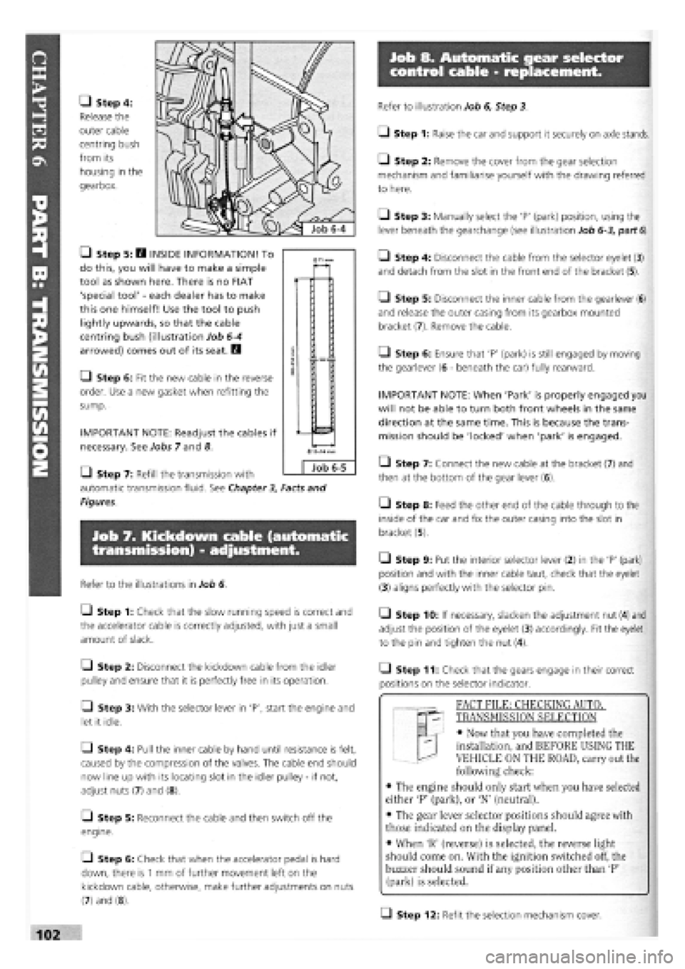
• Step 4:
Release the
outer cable
centring bush
from its
housing in the
gearbox.
• Step 5: H INSIDE INFORMATION! To
do this, you will have to make a simple
tool as shown here. There is no FIAT
'special tool'
-
each dealer has to make
this one himself! Use the tool to push
lightly upwards, so that the cable
centring bush (illustration Job
6-4
arrowed) comes out of its seat. B
• Step 6: Fit the new cable in the reverse
order. Use a new gasket when refitting the
sump.
IMPORTANT NOTE: Readjust the cables if
necessary. See Jobs 7 and 8.
Q Step 7: Refill the transmission with
automatic transmission fluid. See Chapter
3,
Facts and
Figures.
Job 7. Kickdown cable (automatic
transmission) - adjustment.
Refer to the illustrations in Job 6.
Q Step 1: Check that the slow running speed is correct and
the accelerator cable is correctly adjusted, with just a small
amount of slack.
Q Step 2: Disconnect the kickdown cable from the idler
pulley and ensure that it is perfectly free in its operation.
• Step 3: With the selector lever in 'P', start the engine and
let it idle.
Q Step 4: Pull the inner cable by hand until resistance is felt,
caused by the compression of the valves. The cable end should
now line up with its locating slot in the idler pulley
-
if not,
adjust nuts (7) and (8).
[_l Step 5: Reconnect the cable and then switch off the
engine.
• Step 6: Check that when the accelerator pedal is hard
down, there is
1
mm of further movement left on the
kickdown cable, otherwise, make further adjustments on nuts
(7) and (8).
Refer to illustration Job 6, Step 3.
• Step 1: Raise the car and support it securely on axle stands.
• Step 2: Remove the cover from the gear selection
mechanism and familiarise yourself with the drawing referred
to here.
Q Step 3: Manually select the 'P' (park) position, using the
lever beneath the gearchange (see illustration Job
6-3,
part
6).
• Step 4: Disconnect the cable from the selector eyelet (3)
and detach from the slot in the front end of the bracket (5).
Q Step 5: Disconnect the inner cable from the gearlever (6)
and release the outer casing from its gearbox mounted
bracket (7). Remove the cable.
Q Step 6: Ensure that 'P' (park) is still engaged by moving
the gearlever (6
-
beneath the car) fully rearward.
IMPORTANT NOTE: When 'Park' is properly engaged you
will not be able to turn both front wheels in the same
direction at the same time. This is because the trans-
mission should be 'locked' when 'park' is engaged.
• Step 7: Connect the new cable at the bracket (7) and
then at the bottom of the gear lever (6).
• Step 8: Feed the other end of the cable through to the
inside of the car and fix the outer casing into the slot in
bracket (5).
• Step 9: Put the interior selector lever (2) in the 'P' (park)
position and with the inner cable taut, check that the eyelet
(3) aligns perfectly with the selector pin.
• Step 10: If necessary, slacken the adjustment nut (4) and
adjust the position of the eyelet (3) accordingly. Fit the eyelet
to the pin and tighten the nut (4).
• Step 11: Check that the gears engage in their correct
positions on the selector indicator.
T "I FACT FILE: CHECKING AUTOT
qp- TRANSMISSION SELECTION
EL
-
• Now that you have completed the
installation, and BEFORE USING THE
VEHICLE ON THE ROAD, carry out the
following check:
• The engine should only start when you have selected
either 'P' (park), or 'N' (neutral).
• The gear lever selector positions should agree with
those indicated on the display panel.
• When 'R' (reverse) is selected, the reverse light
should come on. With the ignition switched off, the
buzzer should sound if any position other than 'P'
(park) is selected.
Q Step 12: Refit the selection mechanism cover.
0
Job 6-5
Page 125 of 171
Job 4. Steering rack gaiter -
replacement.
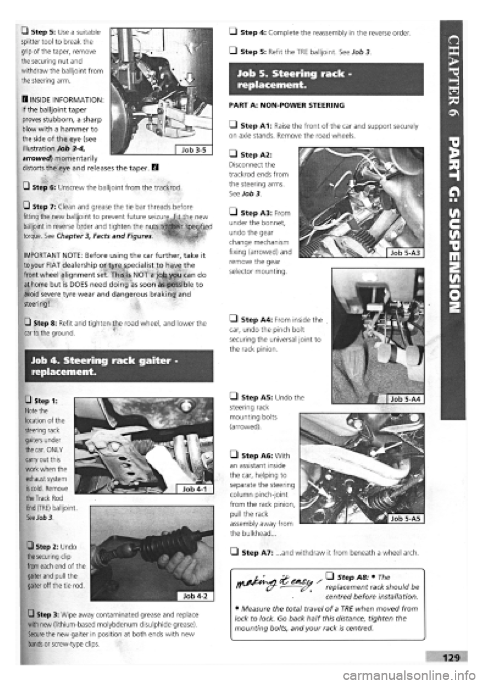
• Step 1:
Note
the
location of the
steering rack
gaiters under
the car.
ONLY
carry out this
work when the
exhaust system
is cold.
Remove
Q Step 5: Use a suitable
splitter tool to break the
grip of the taper, remove
the securing nut and
withdraw the balljoint from
the steering arm.
B INSIDE INFORMATION:
If the balljoint taper
proves stubborn, a sharp
blow with a hammer to
the side of the eye (see
illustration Job
3-4,
arrowed) momentarily
distorts the eye and releases the taper. B
G Step 6: Unscrew the balljoint from the trackrod.
Q Step 7: Clean and grease the tie bar threads before
fitting the new balljoint to prevent future seizure,.fit the new
balljoint in reverse order and tighten the
torque. See Chapter 3, Facts and Figures.
1 ' ™
IMPORTANT NOTE: Before using the car further, take it
to
your FIAT dealership or tyre specialist to have the
front wheel alignment set. This4s NOT a job you can do
at home but is DOES need doing as soon as possible to
avoid severe tyre wear and dangerous braking and
steering!
Q Step 8: Refit and tighten the road wheel, and lower the
car to
the ground.
Q Step 3: Wipe away contaminated grease and replace
with new (lithium-based molybdenum disulphide grease).
Secure
the new gaiter in position at both ends with new
bands
or screw-type clips.
the Track
Rod
End
(TRE) balljoint.
See Job 3.
0 Step 2: Undo
the securing
clip
from
each end of the
gaiter
and
pull the
gaiter off the tie rod.
Q Step 4: Complete the reassembly in the reverse order.
• Step 5: Refit the TRE balljoint. See Job 3
Job 5. Steering rack -
replacement.
PART A: NON-POWER STEERING
Q Step A1: Raise the front of the car and support securely
on axle stands. Remove the road wheels.
• Step A5: Undo the
steering rack
mounting bolts
(arrowed).
• Step A2:
Disconnect the
trackrod ends from
the steering arms.
See Job 3.
Q Step A3: From
under the bonnet,
undo the gear
change mechanism
fixing (arrowed) and
remove the gear
selector mounting.
• Step A4: From inside the
car, undo the pinch bolt
securing the universal joint to
the rack pinion.
• Step A6: With
an assistant inside
the car, helping to
separate the steering
column pinch-joint
from the rack pinion,
pull the rack
assembly away from
the bulkhead...
• Step A7: ...and withdraw it from beneath a wheel arch.
replacement rack should be
centred before installation.
• Measure the total travel of a TRE when moved from
lock to lock. Go back half this distance, tighten the
mounting bolts, and your rack is centred.
Page 126 of 171
Q Step A9: Place the steering wheel in the dead ahead
position and engage the rack pinion splines with the column
coupling.
Q Step A10: Continue refitting in the reverse order of
removal.
• Step A11: Take your car to your nearest FIAT dealership
or tyre specialist to have the front wheel alignment set before
using the car further. This is NOT a job you can do at home
but is DOES need doing as soon as possible to avoid severe
tyre wear and dangerous braking and steering!
PART B: POWER STEERING RACK
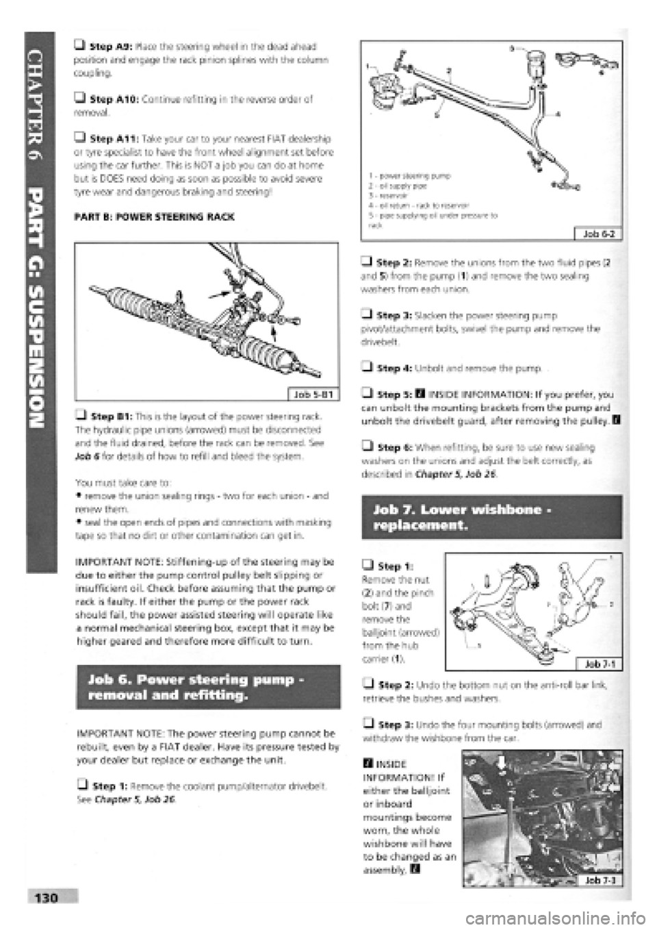
LI Step B1: This is the layout of the power steering rack.
The hydraulic pipe unions (arrowed) must be disconnected
and the fluid drained, before the rack can be removed. See
Job 6 for details of how to refill and bleed the system.
You must take care to:
• remove the union sealing rings
-
two for each union
-
and
renew them.
• seal the open ends of pipes and connections with masking
tape so that no dirt or other contamination can get in.
IMPORTANT NOTE: Stiffening-up of the steering may be
due to either the pump control pulley belt slipping or
insufficient oil. Check before assuming that the pump or
rack is faulty. If either the pump or the power rack
should fail, the power assisted steering will operate like
a normal mechanical steering box, except that it may be
higher geared and therefore more difficult to turn.
Job 6. Power steering pump
removal and refitting.
IMPORTANT NOTE: The power steering pump cannot be
rebuilt, even by a FIAT dealer. Have its pressure tested by
your dealer but replace or exchange the unit.
[_) Step 1: Remove the coolant pump/alternator drivebelt.
See Chapter
5,
Job 26.
• Step 2: Remove the unions from the two fluid pipes (2
and 5) from the pump (1) and remove the two sealing
washers from each union.
Q Step 3: Slacken the power steering pump
pivot/attachment bolts, swivel the pump and remove the
drivebelt.
• Step 4: Unbolt and remove the pump.
• Step 5: B INSIDE INFORMATION: If you prefer, you
can unbolt the mounting brackets from the pump and
unbolt the drivebelt guard, after removing the pulley. I
• Step 6: When refitting, be sure to use new sealing
washers on the unions and adjust the belt correctly, as
described in Chapter
5,
Job 26
Job 7. Lower wishbone
replacement.
• Step 1:
Remove the nut
(2) and the pinch
bolt (7) and
remove the
balljoint (arrowed)
from the hub
carrier (1).
• Step 2: Undo the bottom nut on the anti-roll bar link,
retrieve the bushes and washers.
• Step 3: Undo the four mounting bolts (arrowed) and
withdraw the wishbone from the car.
H INSIDE
INFORMATION! If
either the balljoint
or inboard
mountings become
worn, the whole
wishbone will have
to be changed as an
assembly. E3
130
1 - power steering pump 2 - oil supply pipe 3 - reservoir 4 - oil return - rack to reservoir 5 - pipe supplying oil under pressure to rack Job
6-2
Page 129 of 171
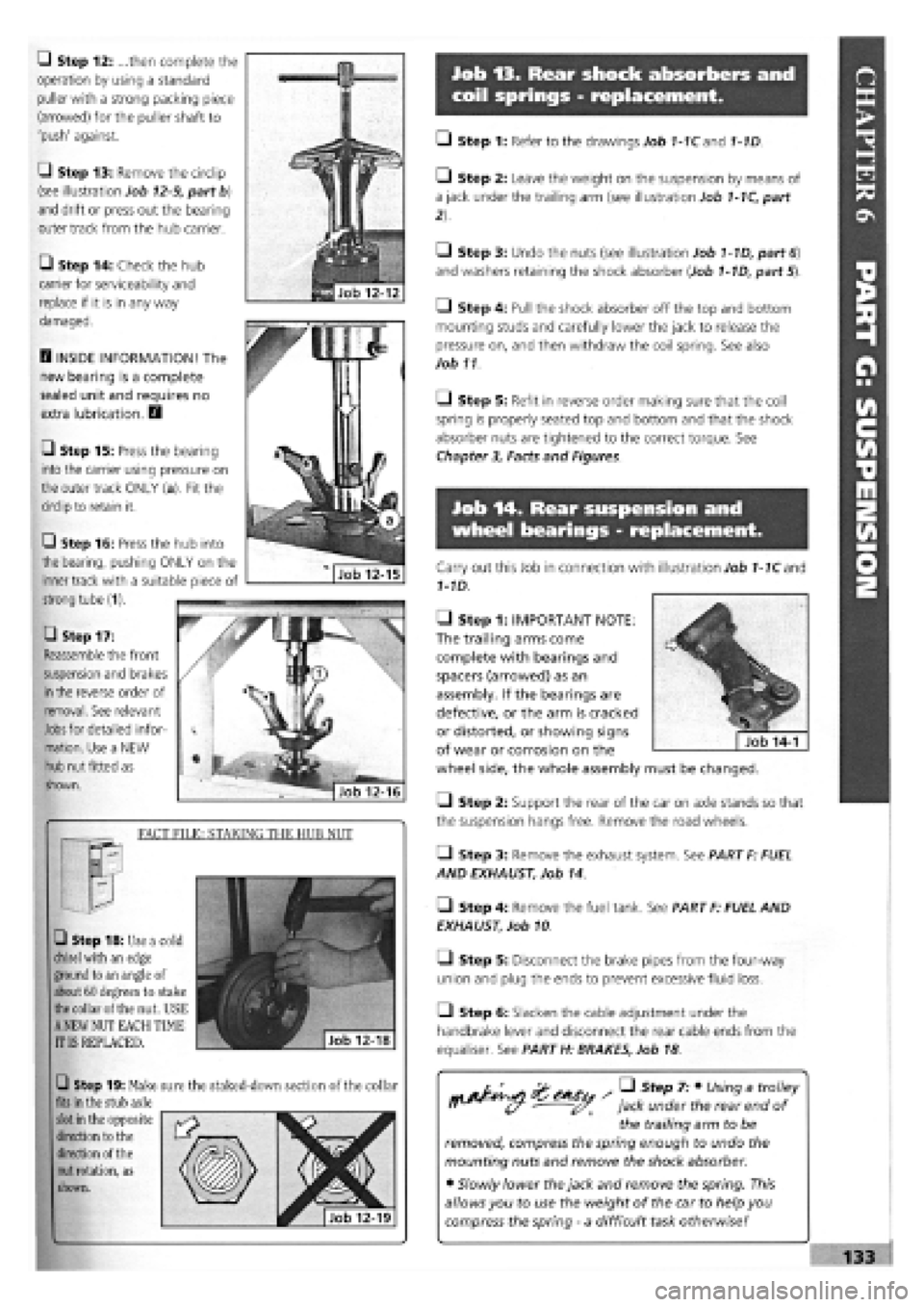
Job 13. Rear shock absorbers and
coil springs - replacement.
Q Step 12: ...then complete the
operation by using a standard
puller with a strong packing piece
(arrowed) for the puller shaft to
'push' against.
G Step 13: Remove the circlip
(see illustration Job
12-9,
part b)
and drift or press out the bearing
outer track from the hub carrier.
• Step 14: Check the hub
carrier for serviceability and
replace if it is in any way
damaged.
D INSIDE INFORMATION! The
new bearing is a complete
sealed unit and requires no
extra lubrication. D
• Step 15: Press the bearing
into the carrier using pressure on
the outer track ONLY (a). Fit the
circlip to retain it.
• Step 17:
Reassemble the front
suspension and brakes
in
the reverse order of
removal. See relevant
Jobs
for detailed infor-
mation. Use a NEW
hub nut fitted as
shown.
FACT FILE: STAKING THE HUB NUT
• Step 18: Use a cold
chisel
with an edge
ground to an angle of
about 60 degrees to stake
the
collar of the nut. USE
A
NEW NUT EACH TIME
IT IS REPLACED.
Q Step 19: Make sure the staked-down section of the collar
fits
in the stub axle
slot
in the opposite
direction to the
direction of the
nut
rotation, as
shown.
• Step 1: Refer to the drawings Job 1-1Cand 1-1D.
• Step 2: Leave the weight on the suspension by means of
a jack under the trailing arm (see illustration Job
1-1C,
part
• Step 3: Undo the nuts (see illustration Job
1-1D,
part
6)
and washers retaining the shock absorber (Job
1-1D,
part 5).
• Step 4: Pull the shock absorber off the top and bottom
mounting studs and carefully lower the jack to release the
pressure on, and then withdraw the coil spring. See also
Job 11
O Step 5: Refit in reverse order making sure that the coil
spring is properly seated top and bottom and that the shock
absorber nuts are tightened to the correct torque. See
Chapter
3,
Facts and Figures.
Job 14. Rear suspension and
wheel bearings - replacement.
Carry out this Job in connection with illustration Job
1-1C
and
1-1D.
• Step 1: IMPORTANT NOTE:
The trailing arms come
complete with bearings and
spacers (arrowed) as an
assembly. If the bearings are
defective, or the arm is cracked
or distorted, or showing signs
of wear or corrosion on the
wheel side, the whole assembly must be changed.
Q Step 2: Support the rear of the car on axle stands so that
the suspension hangs free. Remove the road wheels.
• Step 3: Remove the exhaust system. See PART F: FUEL
AND EXHAUST, Job 14.
• Step 4: Remove the fuel tank. See PART F: FUEL AND
EXHAUST, Job 10
• Step 5: Disconnect the brake pipes from the four-way
union and plug the ends to prevent excessive fluid loss.
Q Step 6: Slacken the cable adjustment under the
handbrake lever and disconnect the rear cable ends from the
equaliser. See PART H: BRAKES, Job 18
/ • Step 7: • Using a trolley
jack under the rear end of
the trailing arm to be
removed, compress the spring enough to undo the
mounting nuts and remove the shock absorber.
• Slowly lower the jack and remove the spring. This
allows you to use the weight of the car to help you
compress the spring
-
a difficult task otherwise!
Q Step 16: Press the hub into
the bearing, pushing ONLY on the
inner track with a suitable piece of
strong tube (1).
Page 171 of 171

A Accelerator linkages and cables 118,119 Aerial 112 Airbag 14, 63, 128 Air cleaner/filter 51 Air Conditioning 12,41 Alternator, drive belt . . 49, 50, 110 Antifreeze 43, 44 Anti-roll bars 131 Auto-Biography 1 Automatic transmission fluid 45 gear selector cable 102
B Ball-joints steering and suspension 57 Battery disconnecting 36 electrolyte 36 safety 7 Bellows, steering gear (see 'Gaiters') Bonnet 15, 143 Brakes 59 to 62, 134 to 142 bleeding 141 caliper 59 to 61, 135, 137 cylinder (master) 138 discs, front 59, 135 discs, rear 61, 137 drums 60, 136 fluid, check level 35,36 handbrake 61, 142 hoses/pipes 62, 141 pads 59, 135, 137 pressure regulating/proportioning . . . valve (ABS) 140 pressure regulating/proportioning valve (Non-ABS) 139 RPM sensors (ABS systems) .... 140 safety 7 servo 138 shoes 135 wear sensors (non-ABS) 60 Bulb renewal (see 'Lights') Bushes 57 Bumper removal and refitting. 146
c Cables accelerator 118,119 automatic transmission ... 101, 102 choke 119 clutch 46, 101 handbrake 61 Caliper, brakes (see 'Brakes') Camshaft belt 43, 66 Capacities 19,154 Carburettor adjustment 53 removal 117 Catalytic converter 54, 55 safety 6 Central locking 114 Choke 119 Clutch adjustment 46, 100 hydraulic 46, 105 replacement 100 cable 46, 101 Coil, ignition 47, 107, 108 Coil spring 57 Constant Velocity (C.V.) joints (see 'Driveshaft') Contents 4 Controls and switches ... 10 to 14 Cooling system .. 35, 43, 106 to107 change coolant 43 radiator pressure cap 35 Crankcase ventilation system 42 Cylinder head Diesel 87 to 93
Petrol 67 to 73
D Data 17 to 27 Diesel bleeding the system 126,127 fuel filter 52 glow plugs 115 injection pump 56,124 injectors 126 Disc, brakes (see 'Brakes') Distributor 108, 109 cap 47 Marelli Breakerless 48 Marelli Digiplex 2 48, 49 Doors hinges 62 locKs and handles 147 to 150 removal and refitting 147 trim panels 146 Drivebelts alternator 49, 50, 110 camshaft 43 Driveshaft C.V. joints 103 gaiters 45, 103 removal and refitting 103 Drum (see 'Brakes')
E Electrical system 110 to 115 Electronic control module 54 safety 7 Emergency starting 16 Emissions 31, 51 to 56 control 53, 54 legal limits 31 Engine bay layouts 34 Engine dismantling Diesel 95 Petrol 73 Engine mountings Diesel 95 Petrol 83 Engine oil (see 'Oil') check level 34 Engine refitting Diesel 94 Petrol 82 Exhaust manifold 56 Exhaust 56 system 56, 122 Expansion tank 35
F Facts & Figures 17 to 27 Fan 50, 106 Fast idle carburettor 53, 54 fuel injection 54 diesel 55 Filter air 51 diesel 52 petrol 52 oil (see 'Oil filter') pollen 63 Fire Extinguisher . 6 Fluoroelastomers, safety 8 Fuel cut-off switch 13 Fuel gauge 114 Fuel injection 52, 54, 55, 117 Fuel lines/pipes 51 Fuel pump electric 120 mechanical 120 Fuel system 51 to 56 evaporation control system . 54,122 Fuel tank 121 Fumes, safety 6 Fuses 40
Gearbox (transmission) .... 44 to 46 oil (automatic) . . 45 oil (manual) 44 Generator drive belt (see 'Alternator, drive belt')
H Handbrake 61, 142 Headlights (see 'Lights') adjustment 62 bulb replacement 37 Headrest 153 Heater 11 Hoses/pipes (see 'Pipes and hoses') HT leads 47 Hub front 104 rear 134
I Identification numbers 27 Idle speed adjustment (see 'Carburettor') Ignition system 46 to 51, 107 to 109 coil 47,48 safety 7 Ignition timing 19, 48 to 50 Instruments 110 panel lights 10 Intercooler 123, 124
J Jacking safety 5 wheelchange 15, 16 Jump leads (Jump starting) 16
L Lambda sensor ... 54, 55, 121, 122 Lights fog lights 13, 38 hazard warning 13 headlights 13,37 indicators 13, 37 interior 15, 39, 40 MoT 28 number plate 39 rear lights 38 reversing lights 39 sidelights 13, 37 Locks and latches 9, 10, 62 Lubricants 154
m Manifold fixings 56 Mirrors 14, 150 Mixture adjustment (see 'Carburettor') Model years 17, 18 MoT, getting through 28 to 31
m Number plates (lights) . . 28, 39, 145
o Oil change disposal 7, 8 engine 41, 42 transmission 44, 45 safety 7 Oil filler cap 35 Oil filter 41 Oil level engine 34, 35 gearbox 44, 45 topping up 35
P-Pads, brake (see 'Brakes') Pipes and hoses brakes 62, 138, 141 hot air 121 radiator (cooling system) 43 Plastics, safety 7 Production changes 17, 18
ft Radiator .* 106 Raising the car 5 Repair data 20 Road test, brakes and steering ... 63 Rotor arm 47, 49
s Safety First! 5 to 8 Seats 14, 151 to 153 mountings 62 Seat belts mountings 62 pretensioners 151, 152 Servicing Your Car 32 to 63 Shock absorbers 57,131 Shoes, brake (see 'Brakes') Sidelights (see 'Lights') Spark plugs 47, 154 Specifications (see 'Facts & Figures') Speedometer cable 110 Starter motor 110 Steering 57, 58, 127 to 131 lower wishbone 127, 130 power steering 58, 130 rack gaiters 58, 133 Steering wheel 128 Sun roof 151 Suspension ... 57 to 59, 127 to 134 front 57, 127, 131 rear 58, 59, 128, 133 strut 57, 131
T Tailgate wiper (see 'Windscreen wipers') Tailgate and strut 144 Thermostat 107 Throttle cable and pedal (see 'Accelerator, linkage and cables') Timing belt 43 Diesel 85 to 87 Petrol 65, 66 Torque wrench settings ... 23 to 27 Track control arm (inner bushes). . 57 Track rod ends 57, 58, 128 Transmission. . 80 to 83, 95, 98 to 106 removal 80 to 82 separation and reconnection (Diesel). . 95 separation and reconnection (Petrol). . 83 Transmission fluid 44, 45 Turbocharger replacement 122 to 124 Tyre checking 30, 36 pressures 18,36
u Universal joints 28, 58 Using your car 9 to 16
¥ Vacuum unit, distributor 48 Valve clearances 42, 43, 79, 93 Valve grinding 72 Vehicle Identification Numbers (VIN) 27
w Washer fluid reservoir 36 Water pump 107 Wheel alignment 28 Wheel bearings 57, 58 Wheel bolts 59 Wheel changing 15,16 Wheel cylinder 137 Wheel sizes 18 Windscreen, damage 29,162 Window regulator 147 to 149 Windscreen washers 112 Windscreen wipers 13,111 Wiring diagrams 155 to 174
Gaiters 30, 57
expert22 fl/ia http://rutracker.org