1987 PORSCHE 944 reset
[x] Cancel search: resetPage 12 of 66
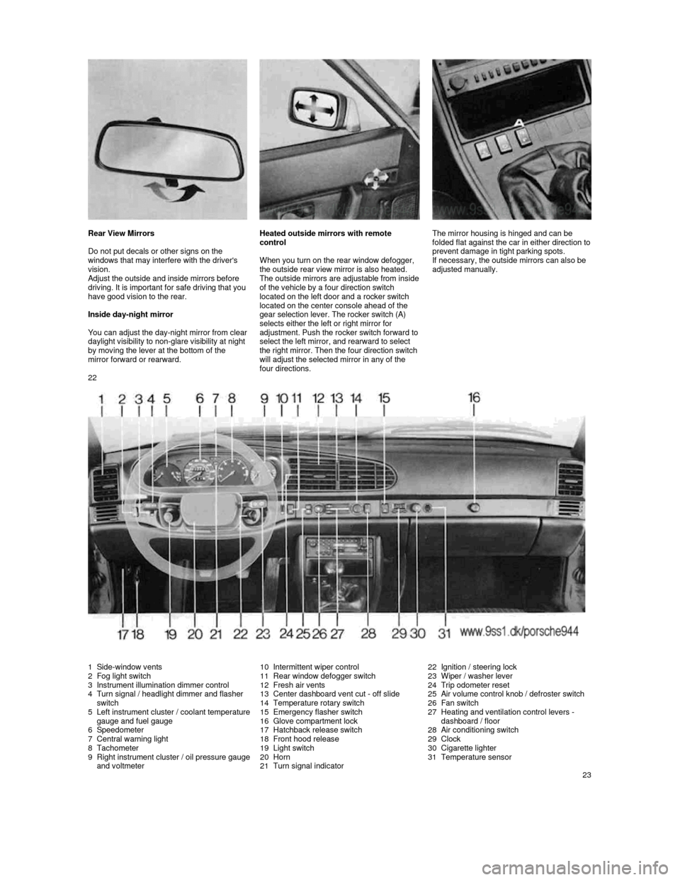
Rear View Mirrors
Do not put decals or other signs on the
windows that may interfere with the driver's
vision.
Adjust the outside and inside mirrors before driving. It is important for safe driving that you have good vision to the rear.
Inside day-night mirror
You can adjust the day-
night mirror from clear daylight visibility to non-glare visibility at night by moving the lever at the bottom of the
mirror forward or rearward.
Heated outside mirrors with remote
control
When you turn on the rear window defogger,
the outside rear view mirror is also heated.
The outside mirrors are ad
justable from inside of the vehicle by a four direction switch
located on the left door and a rocker switch
located on the center console ahead of the
gear selection lever. The rocker switch (A)
selects either the left or right mirror for
adjustment. Push
the rocker switch forward to select the left mirror, and rearward to select
the right mirror. Then the four direction switch
will adjust the selected mirror in any of the four directions.
The mirror housing is hinged and can be
folded flat against the c
ar in either direction to prevent damage in tight parking spots.
If necessary, the outside mirrors can also be
adjusted manually.
22
1 Side-window vents 2 Fog light switch
3 Instrument illumination dimmer control
4 Turn signal / headlight dimmer and flasher
switch
5
Left instrument cluster / coolant temperature gauge and fuel gauge
6 Speedometer
7 Central warning light
8 Tachometer
9 Right instrument cluster / oil pressure gauge and voltmeter
10 Intermittent wiper control
11 Rear window defogger switch
12 Fresh air vents
13 Center dashboard vent cut -
off slide14 Temperature rotary switch
15 Emergency flasher switch
16 Glove compartment lock
17 Hatchback release switch
18 Front hood release
19 Light switch
20 Horn
21 Turn signal indicator
22 Ignition / steering lock
23 Wiper / washer lever
24 Trip odometer reset
25
Air volume control knob / defroster switch
26 Fan switch
27 Heating and ventilation control levers -
dashboard / floor
28
Air conditioning switch
29 Clock
30 Cigarette lighter
31 Temperature sensor
23
Page 15 of 66
ABS Brake System (Antilock brake system)
The ABS system represents a major
contribution to the enhancement of active
safety in your vehicle. This system prevents
the wheels from locking in a panic stop on
almost all road surfaces.
With ABS system in your vehicle, the
following areas are enhanced:
Full steerability , vehicle remains steerable
under all braking forces.
Good directional control , no swerving
caused by locking of wheels under braking
conditions.
Excellent stopping distance , stopping
distances are usually reduced because
controlled braking is maximized.
Prevention of wheel lock up , no brake-
induced sliding and thus no localized tire wear from emergency braking.
The crucial advantage of ABS system over a
conventional brake system is in the area of
maintaining directional control and
maneuverability of the car in emergency
situations, including panic braking in turns.
WARNING:
In spite of the improved handling afforded
by the ABS system, it still remains the
responsibility of the driver to adapt the
driving style to the prevailing road and
weather conditions, as well as, obeying
traffic laws. In no case, should the higher
degree of safety offered by ABS be
regarded as a
justification for taking greater risks. Other vehicles not equipped with the ABS
system may not be able to maintain
control, especially on wet or poor road
surfaces and thus may be more likely to
impact you in the rear. To minimize that r
isk, use your ABS system to increase your ability to maneuver to avoid dangerous
situations and not merely to try to stop in
the shortest distance possible.
Driving with the ABS System
A wheel speed sensor is fitted to each of the four wheels. If wheel slippage of either of the
front wheels or the rear wheels is sensed
during braking, the brake pressure is adjusted
automatically until the wheel no longer slips.
The brake pressure is regulated for each front
wheel individually and for both rear wheels together.
On a road surface which is slippery on only
one side, the rear wheel which is braking on
the slippery surface determines the brake
pressure which will be applied equally to both
rear wheels. This ensures that directional
stability is maintained. However, if braking
force approaches the wheel locking-up point
for all wheels (panic braking) the ABS system
will intervene in a way comparable with rapid rhythmic braking. The proper operation of ABS is perceived by the driver as a pulsating brake pedal in conjunction with audible noise
and perhaps some vibration. The driver is
thereby warned to reduce vehicle speed
appropriate for the prevailing road conditions.
If your ABS system should ever malfunction,
the ABS system is automatically switched off,
but the normal brake system, without ABS,
would remain fully operational. Such a malfunction would be indicated by the illumination of the central warning light, as well as the "ANTILOCK" light on the right hand
side of the instrument cluster.
If the ABS system becomes inoperative,
take your vehicle to your authorized dealer immediately.
Note
The control unit of the ABS brake system is
set for standard tire sizes. If non-standard
tires are fitted, the control unit may
misinterpret the speed of the vehicle, because of the variant data it receives from the sensors on the axles.
If the difference in rolling radius exceeds
approx. 17%, the control unit deactivates the
ABS system and the ABS warning lamp lights up.
28
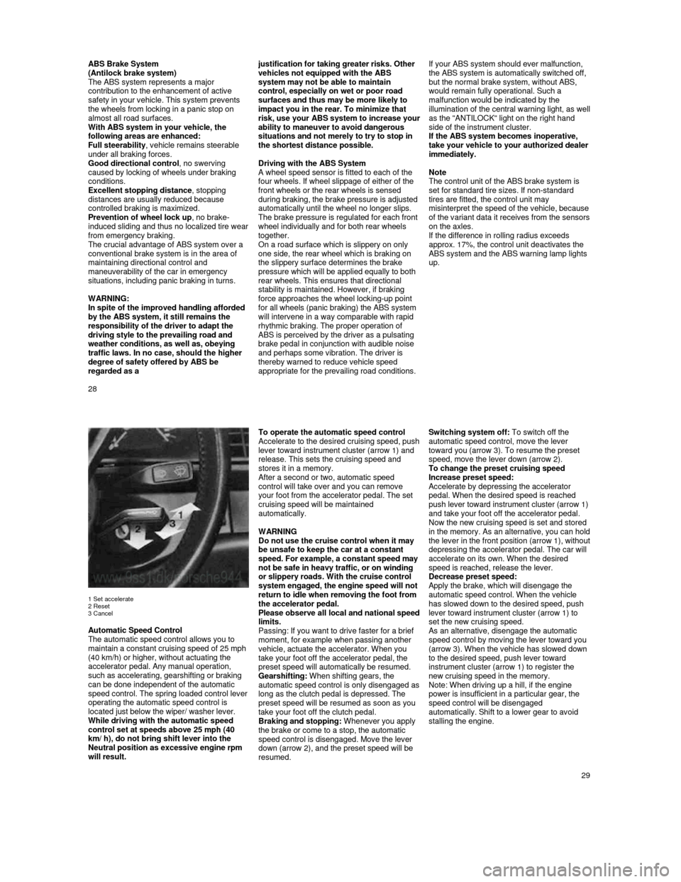
1 Set accelerate
2 Reset
3 Cancel
Automatic Speed Control
The automatic speed control allows you to
maintain a constant cruising speed of 25 mph
(40 km/h) or higher, without actuating the
accelerator pedal. Any manual operation,
such as accelerating, gearshifting or braking
can be done independent of the automatic
speed control. The spring loaded control lever
operating the automatic speed control is
located just below the wiper/ washer lever.
While driving with the automatic speed
control set at speeds above 25 mph (40
km/ h), do not bring shift lever into the
Neutral position as excessive engine rpm
will result.
To operate the automatic speed control Accelerate to the desired cruising speed, push lever toward instrument cluster (arrow 1) and
release. This sets the cruising speed and
stores it in a memory.
After a second or two, automatic speed control will take over and you can remove
your foot from the accelerator pedal. The set
cruising speed will be maintained
automatically.
WARNING
Do not use the cruise control when it may
be unsafe to keep the car at a constant
speed. For example, a constant speed may not be safe in heavy traffic, or on winding
or slippery roads. With the cruise control
system engaged, the engine speed will not
return to idle when removing the foot from
the accelerator pedal.
Please observe all local and national speed limits.
Passing: If you want to drive faster for a brief
moment, for example when passing another
vehicle, actuate the accelerator. When you
take your foot off the accelerator pedal, the
preset speed will automatically be resumed.
Gearshifting: When shifting gears, the
automatic speed control is only disengag
ed as long as the clutch pedal is depressed. The
preset speed will be resumed as soon as you
take your foot off the clutch pedal.
Braking and stopping: Whenever you apply
the brake or come to a stop, the automatic
speed control is disengaged. Move the lever
down (arrow 2), and the preset speed will be
resumed.
Switching system off: To switch off the
automatic speed control, move the lever
toward you (arrow 3). To resume the preset
speed, move the lever down (arrow 2).
To change the preset cruising speed
Increase preset speed:
Accelerate by depressing the accelerator pedal. When the desired speed is reached push lever toward instrument cluster (arrow 1) and take your foot off the accelerator pedal.
Now the new cruising speed is set and stored
in the memory. As an alternative, you can hold the lever in the front position (arrow 1), without depressing the accelerator pedal. The car will
accelerate on its own. When the desired
speed is reached, release the lever.
Decrease preset speed:
Apply the brake, which will disengage the automatic speed control. When the vehicle
has slowed down to the desired speed, push
lever toward instrument cluster (arrow 1) to
set the new cruising speed.
As an alternative, disengage the automatic
speed control by moving the lever toward you
(arrow 3). When the vehicle has slowed down
to the desired speed, push lever toward
instrument cluster (arrow 1) to register the
new cruising speed in the memory.
Note: When driving up a hill, if the engine
power is insufficient in a particular gear, the
speed control will be disengaged
automatically. Shift to a lower gear to avoid
stalling the engine.
29
Page 18 of 66
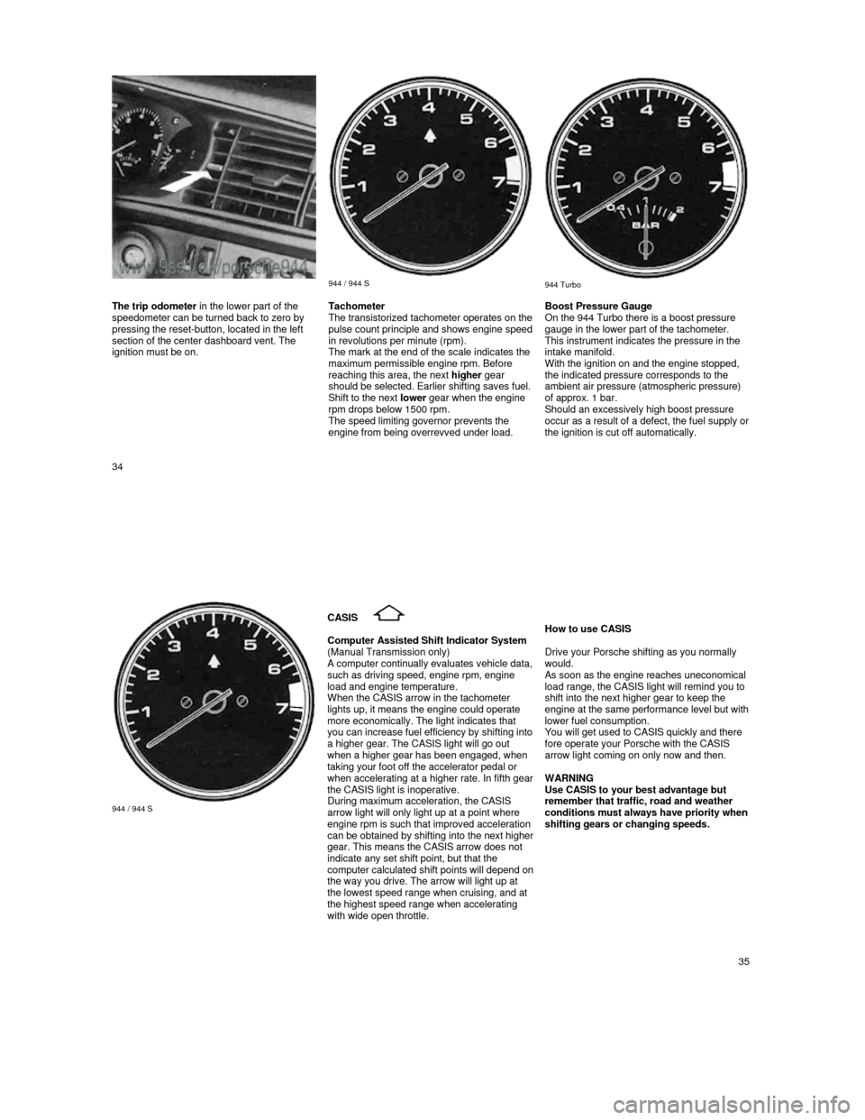
944 / 944 S
944 Turbo The trip odometer
in the lower part of the
speedometer can be turned back to zero by
pressing the reset-button, located in the left
section of the center dashboard vent. The
ignition must be on. Tachometer
The transistorized tachometer operates on the pulse count principle and shows engine speed in revolutions per minute (rpm).
The mark at the end of the scale indicates the
maximum permissible engine rpm. Before
reaching this area, the next higher gear
should be selected. Earlier shifting saves fuel.
Shift to the next lower gear when the engine
rpm drops below 1500 rpm.
The speed limiting governor prevents the
engine from being overrevved under load.
Boost Pressure Gauge
On the 944 Turbo there is a boost pressure
gauge in the lower part of the tachometer.
This instrument indicates the pressure in the
intake manifold.
With the ignition on and the engine stopped,
the indicated pressure corresponds to the
ambient air pressure (atmospheric pressure)
of approx. 1 bar.
Should an excessively high boost pressure
occur as a result of a defect, the fuel supply or the ignition is cut off automatically.
34
944 / 944 S
CASIS
Computer Assisted Shift Indicator System (Manual Transmission only) A computer continually evaluates vehicle data, such as driving speed, engine rpm, engine
load and engine temperature.
When the CASIS arrow in the tachometer
lights up, it means the engine could operate
more economically. The light indicates that
you can increase fuel efficiency by shifting into a higher gear. The CASIS light will go out when a higher gear has been engaged, when taking your foot off the accelerator pedal or when accelerating at a higher rate. In fifth gear the CASIS light is inoperative.
During maximum acceleration, the CASIS
arrow light will only light up at a point where
engine rpm is such that improved acceleration
can be obtained by shifting into the next higher gear. This means the CASIS arrow does not
indicate any set shift point, but that the
computer calculated shift points will depend on the way you drive. The arrow will light up at
the lowest speed range when cruising, and at
the highest speed range when accelerating
with wide open throttle.
How to use CASIS
Drive your Porsche shifting as you normally
would. As soon as the engine reaches uneconomical load range, the CASIS light will remind you to
shift into the next higher gear to keep the
engine at the same performance level but with lower fuel consumption.
You will get used to CASIS quickly and there
fore operate your Porsche with the CASIS
arrow light coming on only now and then.
WARNING
Use CASIS to your best advantage but
remember that traffic, road and weather
conditions must always have priority when shifting gears or changing speeds.
35
Page 21 of 66
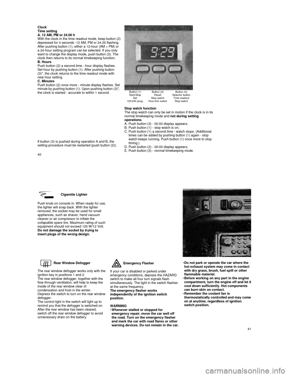
Clock Time setting
A. 12 AM, PM or 24.00 h
With the clock in the time readout mode, keep butto n (2) depressed for 4 seconds -12 AM, PM or 24.00 flashin g. After pushing button (1), either a 12-hour (AM + PM) or
a 24-hour setting program can be selected. If you o nly
want to change the display mode, push button (3). The
clock then returns to its normal timekeeping functi on.
B. Hours
Push button (2) a second time - hour display flashe s.
Set hour by pushing button (1). After pushing butto n
(3)*, the clock returns to the time readout mode wi th
new hour setting.
C. Minutes
Push button (2) once more -
minute display flashes. Set minute by pushing button (1). Upon pushing button ( 3)*, the clock is started - accurate to within 1 second.
Button (1)
Start/Stop Set
12h/24h prog.
Button (2) Reset
Stop watch
Hour/min select
Button (3)
Selector button Time readout Stop watch
If button (3) is pushed during operation A and B, t he
setting procedure must be restarted (push button (2 )).
Stop watch function
The stop watch can only be set in motion if the clo ck is in its
normal timekeeping mode and not during setting
operations .
A. Push button (3) - 00:00 display appears;
B. Push button (1) - stop watch is on;
C. Push button (1) a second time - watch stops. (Addit ional
times can be added by pushing button (1) again - st op
watch keeps running. Push button (1) once more to s top timing.)
D. Push button (2) - 00:00 display appears;
E. Push button (3) - normal timekeeping mode.
40
Cigarette Lighter
Push knob on console in. When ready for use, the lighter will snap back. With the lighter
removed, the socket may be used for small
appliances, such as shaver, hand vacuum
cleaner or air compressor to inflate the
collapsible spare tire. Maximum rating of such
equipment should not exceed 120 W/12 Volt.
Do not damage the socket by trying to
insert plugs of the wrong design.
Rear Window Defogger
The rear window defogger works only with the
ignition key in positions 1 and 2.
The rear window defogger, together with the
flow through ventilation, will help to keep the
inside of the rear window clear of
condensation and frost in the winter.
Depress the switch to turn on the rear window
defogger.
The control light in the switch will light up to
remind you that the defogger is switched on.
After the rear window has been cleared, switch off the rear window defogger to avoid
unnecessary drain on the battery.
Emergency Flasher
If your car is disabled or parked under
emergency conditions, depress the HAZARD
switch to make all four turn signals flash
simultaneously. The light in the switch flashes
at the same frequency.
The emergency flasher works
independently of the ignition switch
position.
WARNING
Whenever stalled or stopped for emergency repair, move the car well off
the road. Turn on the emergency flasher
and mark the car with road flares or other
warning devices. Do not remain in the car.
Do not park or operate the car where the hot exhaust system may come in contact
with dry grass, brush, fuel spill or other
flammable material.
Before working on any part in the engine compartment, turn the engine off and let it cool down sufficiently. Hot components
can burn skin on contact.
Remember the coolant fan is thermostatically controlled and may come on at anytime, regardless of ignition
switch position.
41
Page 23 of 66
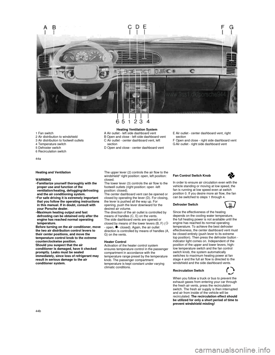
Heating Ventilation System
1 Fan switch
2 Air distribution to windshield
3 Air distribution to footwell outlets
4 Temperature switch
5 Defroster switch
6 Recirculation switch
A Air outlet - left side dashboard vent
B Open and close - left side dashboard vent
C
Air outlet - center dashboard vent, left
section
D Open and close - center dashboard vent
E Air outlet - center dashboard vent, right
section
F
Open and close - right side dashboard vent
G Air outlet - right side dashboard vent
44a
Heating and Ventilation
WARNING
Familiarize yourself thoroughly with the proper use and function of the
ventilation/heating, defogging/defrosting
and the air conditioning system.
For safe driving it is extremely important that you follow the operating instructions
in this manual. If in doubt, consult with
your Porsche dealer.
Maximum heating output and fast defrosting can be obtained only after the
engine has reached normal operating
temperature.
Before turning on the air conditioner, move the two air distribution control levers to
their center positions, and move the
temperature control knob to the extreme
counterclockwise position.
Should you suspect that the air
conditioner is damaged, have it checked
promptly. Leaks must be sealed
immediately, since loss of refrigerant may
result in serious damage to the air
conditioner system.
The upper lever (2) controls the air flow to the windshield" right position: open, left position: closed.
The lower lever (3) controls the air flow to the
footwell outlets (right position: open -left
position: closed).
The center dashboard vent can be opened or
closed by operating the lever (D). For closing,
the lever is pushed all the way up. For
opening, push the lever downward for the
desired air volume.
The direction of the air outlet is controlled by
means of handles (C, E) on the vents.
The side dashboard vents are opened or
closed by means of the lower levers (B, F) (
- open, - closed). Again, the air outlet direction is controlled by means of handles (A, G) on the vents.
Heater Control
Activation of the heater control system ensures temperature control in the passenger
compartment in accordance with the
temperature range preset by the temperature
knob. The passenger compartment
temperature is kept constant under varying
climatic conditions.
Fan Control Switch Knob
In order to ensure air circulation even with the
vehicle standing or moving at low speed, the
fan is running at low speed even at switch
position 0. If you desire more air flow, the fan
can be switched to steps 1 through 4.
Defroster Switch
Since the effectiveness of the heating
depends on the cooling water temperature,
the full heating power is not available until the
engine has reached its normal operating
temperature. To achieve the best defroster
effectiveness, the center dashboard vent must be closed entirely (push lever to its extreme
top position). Then press the defroster button - indicator light comes on. Independent of the
position of the upper and lower levers, high-
low temperature switch and the fan control
switch knob, the system automatically
switches to maximum heating power at fan
stage 4 and the full air flow is directed to the
windshield and the side dashboard vents.
Recirculation Switch
When you follow a truck or bus to prevent the
exhaust gases from entering your car through
the fresh air vents, press the recirculation
switch. The fresh air supply is then interrupted and air from inside of the vehicle will be
recirculated. The recirculation effect should
be utilized for only a short period of time to prevent windshield misting! 44b
Page 24 of 66
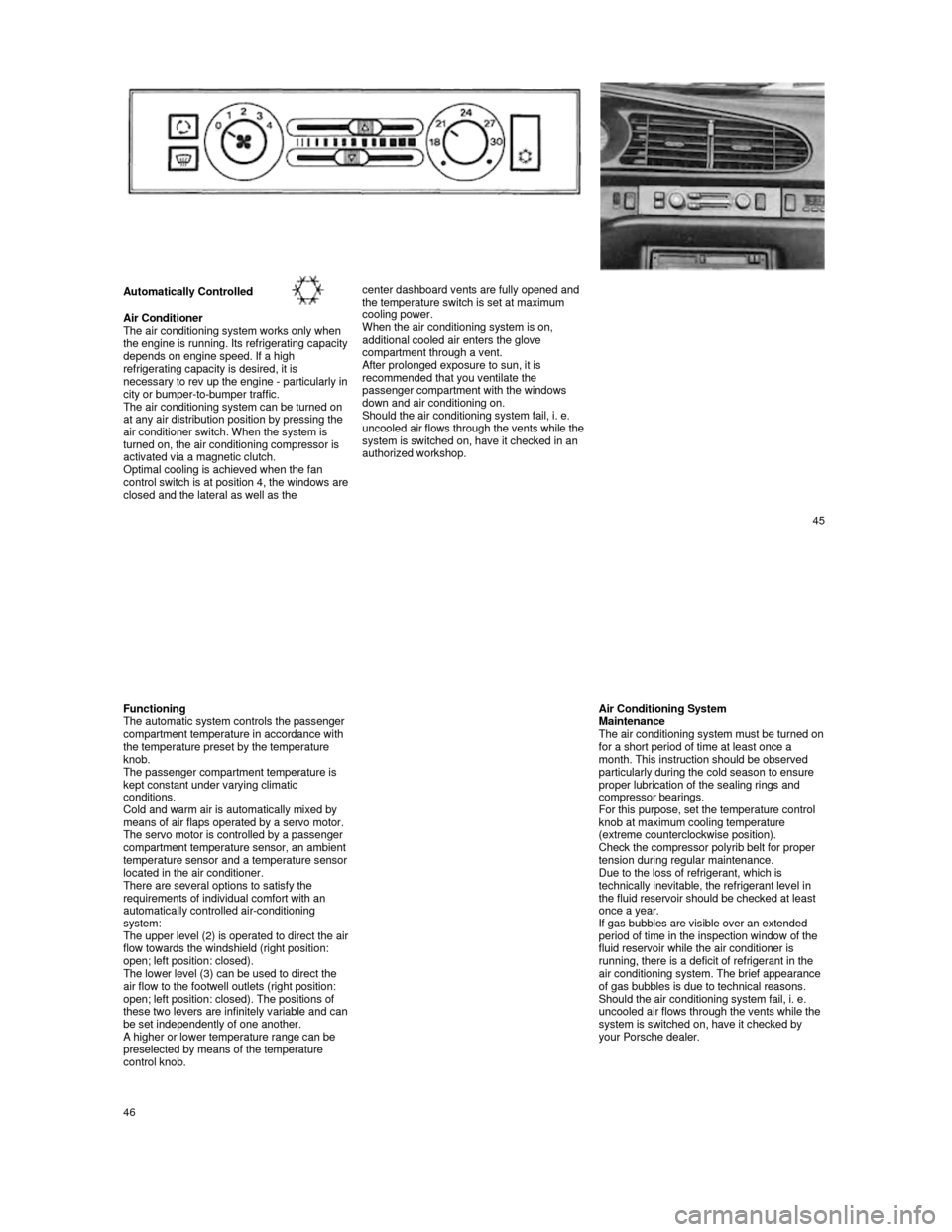
Automatically Controlled
Air Conditioner
The air conditioning system works only when
the engine is running. Its refrigerating capacity depends on engine speed. If a high
refrigerating capacity is desired, it is
necessary to rev up the engine -
particularly in city or bumper-to-bumper traffic.
The air conditioning system can be turned on
at any air distribution position by pressing the
air conditioner switch. When the system is
turned on, the air conditioning compressor is
activated via a magnetic clutch.
Optimal cooling is achieved when the fan
control switch is at position 4, the windows are closed and the lateral as well as the
center dashboard vents are fully opened and
the temperature switch is set at maximum
cooling power.
When the air conditioning system is on,
additional cooled air enters the glove
compartment through a vent.
After prolonged exposure to sun, it is recommended that you ventilate the
passenger compartment with the windows
down and air conditioning on.
Should the air conditioning system fail, i. e.
uncooled air flows through the vents while the
system is switched on, have it checked in an
authorized workshop.
45
Functioning
The automatic system controls the passenger
compartment temperature in accordance with
the temperature preset by the temperature
knob.
The passenger compartment temperature is
kept constant under varying climatic
conditions.
Cold and warm air is automatically mixed by
means of air flaps operated by a servo motor.
The servo motor is controlled by a passenger
compartment temperature sensor, an ambient
temperature sensor and a temperature sensor located in the air conditioner.
There are several options to satisfy the
requirements of individual comfort with an
automatically controlled air-conditioning
system:
The upper level (2) is operated to direct the air flow towards the windshield (right position:
open; left position: closed).
The lower level (3) can be used to direct the
air flow to the footwell outlets (right position:
open; left position: closed). The positions of
these two levers are infinitely variable and can be set independently of one another. A higher or lower temperature range can be preselected by means of the temperature
control knob.
Air Conditioning System Maintenance The air conditioning system must be turned on for a short period of time at least once a
month. This instruction should be observed
particularly during the cold season to ensure
proper lubrication of the sealing rings and
compressor bearings.
For this purpose, set the temperature control
knob at maximum cooling temperature
(extreme counterclockwise position).
Check the compressor polyrib belt for proper
tension during regular maintenance.
Due to the loss of refrigerant, which is
technically inevitable, the refrigerant level in
the fluid reservoir should be checked at least
once a year.
If gas bubbles are visible over an extended
period of time in the inspection window of the
fluid reservoir while the air conditioner is
running, there is a deficit of refrigerant in the
air conditioning system. The brief appearance
of gas bubbles is due to technical reasons.
Should the air conditioning system fail, i. e.
uncooled air flows through the vents while the
system is switched on, have it checked by
your Porsche dealer.
46