1987 PORSCHE 944 low beam
[x] Cancel search: low beamPage 16 of 66

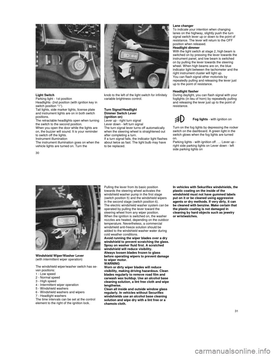
Lane changer
To indicate your intention when changing
lanes on the highway, slightly push the turn
signal switch lever up or down to the point of
resistance. The lever will return to the OFF
position when released.
Headlight dimmer
With the light switch at stage 2, high beam is
switched on by pressing the lever towards the
instrument panel, and low beam is switched
on by pulling the lever towards the steering
wheel. When high beams are on, the blue indicator light between the tachometer and the right instrument cluster will light up.
You can flash signal other motorists by
repeatedly pulling and releasing the lever just
up to the point of resistance.
Light Switch
Parking light - 1st position
Headlights -2nd position (with ignition key in
switch position "1").
Tail lights, side marker lights, license plate
and instrument lights are on in both switch
positions.
The retractable headlights open when turning
the switch to the second position.
When you open the door while the lights are
on, the buzzer will sound. It is your reminder
to switch off the lights.
Instrument illumination
The instrument illumination goes on when the
vehicle lights are turned on. Turn the
knob to the left of the light switch for infinitely
variable brightness control.
Turn Signal/Headlight
Dimmer Switch Lever
(ignition on)
Lever up - right turn signal
Lever down - left turn signal
The turn signal lever turns off automatically
when the steering wheel is straightened out after completing a turn.
If a turn signal fails, the indicator light flashes
about twice as fast. The light bulb may have
to be replaced.
Headlight flasher
During daylight, you can flash signal with your
foglights (in lieu of horn) by repeatedly pulling
and releasing the lever just up to the point of
resistance.
Fog lights
- with ignition on
Turn on the fog lights by depressing the rocker switch on the dashboard. A green light in the
switch glows when the fog lights are turned
on.
Parking lights - with ignition off . ... Lever up -
right side parking lights on Lever down - left
side parking lights on
30
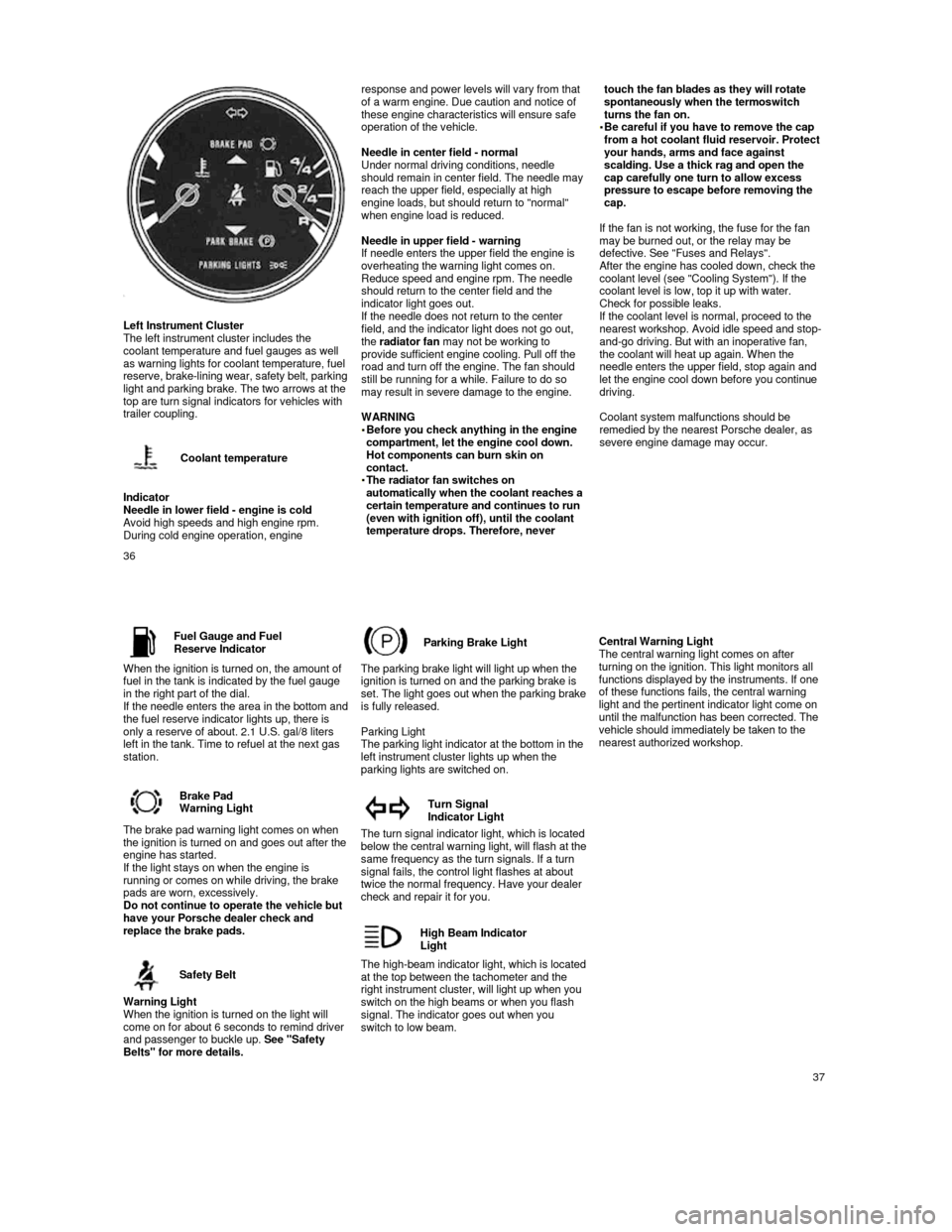
Windshield Wiper/Washer Lever
(with intermittent wiper operation)
The windshield wiper/washer switch has se-
ven positions:
1 - Low speed
2 - Normal speed
3 - High speed
4 - Intermittent wiper operation
5 - Windshield washers
6 - Windshield washers and wipers
7 - Headlight washers
The time intervals can be set at the control
element to the right of the ignition lock.
Pulling the lever from its basic position
towards the steering wheel activates the
windshield washer pump in the first stage
(switch position 5) and the windshield wipers
in the second stage (switch position 6).
The electric windshield washer system can be operated by pulling the lever toward the
steering wheel from any wiper position.
When the ignition is switched on, the washer
nozzles are heated, depending on the outdoor temperature. Nevertheless, a commercial windshield anti-freeze solution should be
added to the windshield washer water during
cold weather conditions.
Avoid running the wiper blades over a dry
windshield to p
revent scratching the glass. Spray on washer fluid first. A scratched
windshield will reduce visibility.
Always loosen blades frozen to glass
before operating wipers to prevent damage to wiper motor.
WARNING
Worn or dirty wiper blades will reduce
visibility, making driving hazardous. Clean
blades regularly to remove road film and
carwash wax buildup. Use an alcohol base
cleaning solution, a lint free cloth and wipe lengthwise.
Clean all inside and outside window glass
regularly. In vehicles without Securiflex
windshields use an alcohol base cleaning
solution and wipe dry with a lint free or a
chamois cloth.
In vehicles with Sekuriflex windshields, the plastic coating on the inside of the
windshield must not have gummed labels
put on it or be cleaned using aggressive
agents or dry methods. If very dirty, it can
be cleaned with benzine. Make certain that
the plastic coating is not damaged in
cleaning by hard objects such as jewelry
or wristwatches.
31
Page 19 of 66

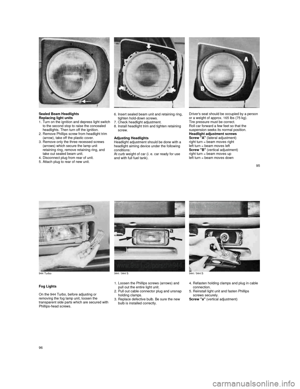
Left Instrument Cluster
The left instrument cluster includes the
coolant temperature and fuel gauges as well
as warning lights for coolant temperature, fuel
reserve, brake-
lining wear, safety belt, parking light and parking brake. The two arrows at the
top are turn signal indicators for vehicles with
trailer coupling.
Coolant temperature
Indicator
Needle in lower field - engine is cold
Avoid high speeds and high engine rpm. During cold engine operation, engine
response and power levels will vary from that
of a warm engine. Due caution and notice of
these engine characteristics will ensure safe
operation of the vehicle.
Needle in center field - normal
Under normal driving conditions, needle
should remain in center field. The needle may
reach the upper field, especially at high
engine loads, but should return to "normal"
when engine load is reduced.
Needle in upper field - warning
If needle enters the upper field the engine is
overheating the warning light comes on.
Reduce speed and engine rpm. The needle
should return to the center field and the
indicator light goes out.
If the needle does not return to the center
field, and the indicator light does not go out,
the radiator fan may not be working to
provide sufficient engine cooling. Pull off the
road and turn off the engine. The fan should
still be running for a while. Failure to do so
may result in severe damage to the engine.
WARNING
Before you check anything in the engine compartment, let the engine cool down.
Hot components can burn skin on
contact. The radiator fan switches on automatically when the coolant reaches a
certain temperature and continues to run
(even with ignition off), until the coolant
temperature drops. Therefore, never
touch the fan blades as they will rotate spontaneously when the termoswitch
turns the fan on.
Be careful if you have to remove the cap from a hot coolant fluid reservoir. Protect
your hands, arms and face against
scalding. Use a thick rag and open the
cap carefully one turn to allow excess
pressure to escape before removing the
cap.
If the fan is not working, the fuse for the fan
may be burned out, or the relay may be
defective. See "Fuses and Relays".
After the engine has cooled down, check the coolant level (see "Cooling System"). If the
coolant level is low, top it up with water.
Check for possible leaks.
If the coolant level is normal, proceed to the
nearest workshop. Avoid idle speed and stop-
and-go driving. But with an inoperative fan,
the coolant will heat up again. When the
needle enters the upper field, stop again and
let the engine cool down before you continue
driving.
Coolant system malfunctions should be
remedied by the nearest Porsche dealer, as
severe engine damage may occur.
36
Fuel Gauge and FuelReserve Indicator
When the ignition is turned on, the amount of
fuel in the tank is indicated by the fuel gauge
in the right part of the dial.
If the needle enters the area in the bottom and the fuel reserve indicator lights up, there is
only a reserve of about. 2.1 U.S. gal/8 liters
left in the tank. Time to refuel at the next gas
station.
Brake Pad
Warning Light
The brake pad warning light comes on when the ignition is turned on and goes out after the engine has started.
If the light stays on when the engine is
running or comes on while driving, the brake
pads are worn, excessively.
Do not continue to operate the vehicle but
have your Porsche dealer check and
replace the brake pads.
Safety Belt
Warning Light
When the ignition is turned on the light will
come on for about 6 seconds to remind driver
and passenger to buckle up. See "Safety
Belts" for more details.
Parking Brake Light
The parking brake light will light up when the
ignition is turned on and the parking brake is
set.
The light goes out when the parking brake is fully released.
Parking Light
The parking light indicator at the bottom in the
left instrument cluster lights up when the
parking lights are switched on.
Turn Signal
Indicator Light
The turn signal indicator light, which is located below the central warning light, will flash at the same frequency as the turn signals. If a turn
signal fails, the control light flashes at about
twice the normal frequency. Have your dealer
check and repair it for you.
High Beam Indicator
Light
The high-beam indicator light, which is located at the top between the tachometer and the
right instrument cluster, will light up when you
switch on the high beams or when you flash
signal. The indicator goes out when you
switch to low beam.
Central Warning Light
The central warning light comes on after
turning on the ignition. This light monitors all
functions displayed by the instruments. If one
of these functions fails, the central warning
light and the pertinent indicator light come on
until the malfunction has been corrected. The
vehicle should immediately be taken to the
nearest authorized workshop.
37
Page 49 of 66

Sealed Beam Headlights
Replacing light units
1.
Turn on the ignition and depress light switch to the second stop to raise the concealed
headlights. Then turn off the ignition.
2.
Remove Phillips screw from headlight trim
(arrow), take off the plastic cover.
3.
Remove only the three recessed screws
(arrows) which secure the lamp unit
retaining ring, remove retaining ring, and
take out sealed beam unit.
4.
Disconnect plug from rear of unit.
5. Attach plug to rear of new unit.
6. Insert sealed beam unit and retaining ring,
tighten hold-down screws.
7.
Check headlight adjustment.
8. Install headlight trim and tighten retaining
screw.
Adjusting Headlights
Headlight adjustment should be done with a
headlight aiming device under the following
conditions:
At curb weight of car (i. e. car ready for use
and with full fuel tank).
Driver's seat should be occupied by a person
or a weight of approx. 165 Ibs (75 kg).
Tire pressure must be correct.
Roll car forward a few feet so that the
suspension seeks its normal position.
Headlight adjustment screws
Screw "A" (lateral adjustment)
right turn = beam moves right
left turn = beam moves left
Screw "B" (vertical adjustment)
right turn = beam moves up
left turn = beam moves down
95
944 Turbo
944 / 944 S
944 / 944 S
Fog Lights
On the 944 Turbo, before adjusting or
removing the fog lamp unit, loosen the
transparent side parts which are secured with
Phillips-head screws.
1. Loosen the Phillips screws (arrows) and
pull out the entire light unit.
2.
Pull out cable connector plug and unsnap
holding clamps.
3.
Replace defective bulb. Be sure the new
bulb is installed correctly.
4. Refasten holding clamps and plug in cable
connection.
5.
Reinstall light unit and fasten Phillips
screws securely.
Screw "a" (vertical adjustment)
96