1987 MITSUBISHI MONTERO heater
[x] Cancel search: heaterPage 223 of 284

BACK DOOR WINDOW DEFOGGER - Specifications / Special Tools
BACK DOOR WINDOW DEFOGGER
8-203
SPECIFICATIONS
( ;ENERAL SPECIFICATIONS NOOPB-B
Items
Back door window defogger switch
Type Seesaw type Specifications
Rated current
Back door window defogger timer
Timer
Back door window glass with defogger
No. of printed heater lines
Power consumption [2O”C (68”F)] 20A
-
11
112-148W
SPECIAL TOOLS
Tool (Number and name)
MB990784
Ornament remover Use
Removal of back door
window defogger
switch
NOBPG-B
1 STB Revision
Page 227 of 284

BACK DOOR WINDOW DEFOGGER - Printed Heater Lines B-207
Normal characteristic curve
Voltage
I;\
Positive
terminal Printed heater line Negative
terminal
Abnormal characteristic curve
Voltage
IZV
6V
ov :-
Tf I Open-circuit
I point
I
i
!
Positive Printed heater line Negative
terminal terminal
161332
Alignme.nt holes
Masking tape
16FfiSCl
PRINTED HEATER LINES
INSPECTION N08PKAA
1. The printed heater lines should be tested while the engine
is running at 2,000 rpm and the battery is being charged.
2. Turn the defogger switch to the “ON” position, and use
voltmeter to measure the voltage of each printed heater
line at the back door window glass center point “A”.
3. If all of the heater lines indicate approximately 6V, the back
door window printed heater lines are functioning properly.
4. If a voltage of 12V is indicated at point “A”, the heater line
is broken between point “A” and the negative (-) terminal.
Move the test probe gradually toward the negative (-)
terminal, and search for the place where there is a sudden
change in the voltage (to 0 V).
5. This place where the voltage suddenly changes indicates
the location of the broken heater line.
6. If OV is indicated at point “A”, the heater line is broken
between point “A” and the positive (+) terminal. Find the
point where there is a sudden change in the voltage (to
12V). as described in step 4. above.
REPAIR
I. Prepare the following items:
e Conductive paint
@ Paint thinner
e Masking tape, decal, etc.
a, Unleaded gasoline
@ Thin brush
Wipe the glass adjacent to the broken heater line, clean
with unleaded gasoline, and bond a decal or masking tape
as shown.
2. Shake the electroconductive paint container well, and
remove the amount of paint needed. Dilute it with a small
quantity of paint thinner, and apply three coats with the
brush at intervals of about 15 minutes.
3. Remove the tape or decal and leave the repaired defogger
unused for a while before supplying power.
4. For a better finish, scrape away excess deposits with a
knife after drying is complete (one day later).
Caution
After repair, clean the glass with a soft dry shop towel
or wipe along the printed heater line with a slightly
moistened shop towel.
1 STB Revision
Page 237 of 284

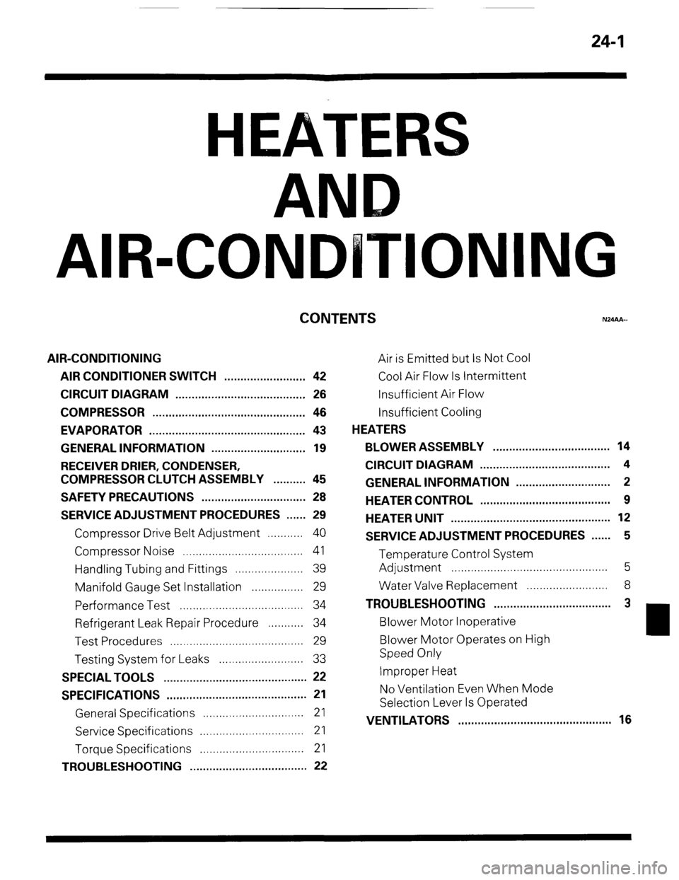
24-1
AIR-CO IONING
CONTENTS
AIR-CONDITIONING
AIR CONDITIONER SWITCH ......................... 42
CIRCUIT DIAGRAM ...................................... . . 26
COMPRESSOR ............................................... 46
EVAPORATOR ............................................ . ... 43
GENERAL INFORMATION .............. . ....... . . . .... 19
RECEIVER DRIER, CONDENSER,
COMPRESSOR CLUTCH ASSEMBLY .......... 45
SAFETY PRECAUTIONS ................................ 28
SERVICE ADJUSTMENT PROCEDURES ...... 29
Compressor Drive Belt Adjustment ...........
40
Compressor Noise ..................................... 41
Handling Tubing and Fittings ..................... 39
Manifold Gauge Set Installation ................ 29
Performance Test ...................................... 34
Refrigerant Leak Repair Procedure ........... 34
Test Procedures ......................................... 29
Testing System for Leaks .......................... 33
SPECIAL TOOLS ............................................ 22
SPECIFICATIONS ...... . .
.. . ................................ 21
General Specifications ...............................
21
Service Specifications ................................
21
Torque Specifications ................................
21
TROUBLESHOOTING .................................... 22 Air is Emitted but Is Not Cool
Cool Air Flow Is Intermittent
Insufficient Air Flow
Insufficient Cooling
HEATERS
BLOWER ASSEMBLY . . . . . . . . . . . . . . . . . . ..a............... 14
CIRCUIT DIAGRAM . . . . . . . . . . . . . . . . . . . . . . . . . . . . . . . . . . . . . . . . 4
GENERAL INFORMATION . . . . . . . . . . . . . . . . . . . . . . . . . . . . . 2
HEATER CONTROL . . . . . . . . . . . . . . . . . . . . . . . . . . . . . . . . . . . . . . . . 9
HEATER UNIT . . . . . . . . . . . . . . . . . . . . . . . . . . . . . . . . . . . . . . . . . . . . . . . . . 12
SERVICE ADJUSTMENT PROCEDURES . . . . . . 5
Temperature Control System
Adjustment . . . . . . . . . . . . . . . . . . . . . . . . . . . . . . . . . . . . . . . . . . . . . . . . 5
Water Valve Replacement . . . . . . . . . . . . . . . . . . . . . . . 8
TROUBLESHOOTING . . . . . . . . . . . . . . . . . . . . . . . . . . . . . . . . . . . . 3
Blower Motor Inoperative
Blower Motor Operates on High
Speed Only
Improper Heat
No Ventilation Even When Mode
Selection Lever Is Operated
VENTILATORS . . . . . . . . . . . . . . . . . . . . . . . . . . . ..a..... . . . . . . . . . . . .
16
Page 238 of 284

24-2 HEATERS - General Information
GENERAL INFORMATION 24BAAD
The heater unit and the blower motor are the separate type.
For temperature control of the heater, the blend air system is used for excellent response and easy
temperature adjustment.
Because the damper in the blend air system controls the warm air, which passes through the heater core,
and fresh (cool) air, which does not pass througlh the core, minor adjustments of the temperature are
therefore possible, and the temperature’can be ,set to the optimum level.
The lap heater ducts (which provide warm air to th$ knee area for the front seats) and the-rear heater ducts
(which provide warm air to the foot area for the rebr seats) from the heater unit, plus the warm-water-type
rear heater, assure heating comfort throughout. :
Blower motor
/
2OW640
Rear heater duct ;;eselection
I Mode selection lever
I I
58W540 Temperature
Blower switch contra’ lever To defroster and
Blend air Air selection
demister damper damper
Fresh air
Mode selection
damper (VENT) To lap heater &@
duct To foot area
ro rear heater duct To rear heater duct 2OW706 Mode selection damper (FOOT/DEF)
1 ST6 Revision
Page 239 of 284

TROUBLESHOOTING
HEATERS -Troubleshooting 24-3
N24EAAC
Reference
Symptom Probable cause Remedy
paw
Improper heat Obstructed floor outlets Correct -
’ Changeover dampers improperly adjusted Correct 24-5
or binding
, Thermostat malfunction
Replace -
Obstructed heater hoses
Replace 24-l 2
’ Improperly adjusted control cables
Adjust 24-5
Plugged or partially plugged heater core
Clean or replace 24-l 3
No ventilation even Incorrect adjustment of changeover dam-
Adjust 24-5
when mode selection pers
lever is operated
Incorrect installation mode selection control
Adjust 24-5
wire
Blower motor oper-
ates on high speed
only
Blower motor inop-
erative Ducts are incorrectly/incompletely con-
netted, crushed, bent or clogged.
Broken blower motor resister
Broken blower switch
Burnt-out fuse
Poor grounding
Malfunction blower switch
Malfunction blower motor Repair or replace
Replace
Replace
Replace
Correct
Replace
Replace -
24-l 5
24-l 0
-
-
24-l 0
24-l 4 1 STB Revision
Page 240 of 284

24-4 HEATERS c Circuit Diagram
CIRCUIT DIAGRAM
I
El3 1 El1
lanition switch
Sub fusible link
Battery link m- (Fuse B)
3
1 I (Ignition switch)
Multi-purpose Q
fuse
M $5
LA,:
a3
To turn sional flasher (Init
0.85RI I I f-Y ’ I [Refer to P.8-49.7- - - ‘d -r i
I Blower
Blower switch
CJ -18
Heater r&v Blower motor ?
resistor
Remark
For information concerning the ground points (example:
q ),
refer to P.8-7.
Wiring color code
B: Black Br. Brown
G: Green
Gr: Gray
LI: Light blue
0: Orange P: Pink
R: Red L: Blue
Y: Yellow Lg: Light green
W: White
1 STB Revision
Page 241 of 284

HEATERS - Service Adjustment Procedures 24-5
SERVICE DJUSTMENT PROCEDURES
TEMPERATURE CONTROL SYSTEM ADJUST-
ENT
N24FAAD
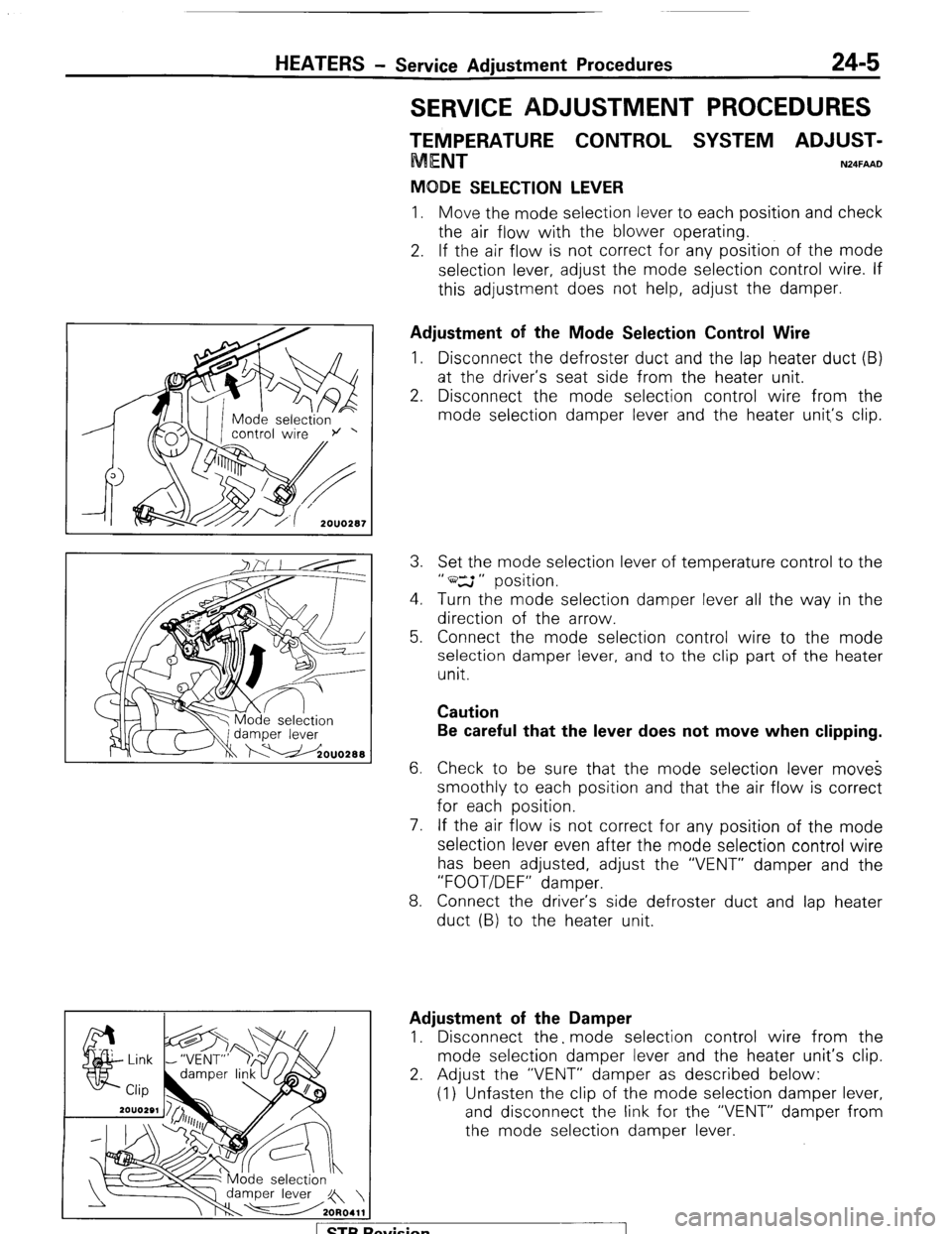
MODE SELECTION LEVER
1. Move the mode selection lever to each position and check
the air flow with the blower operating.
2. If the air flow is not correct for any position of the mode
selection lever, adjust the mode selection control wire. If
this adjustment does not help, adjust the damper.
Adjustment of the Mode Selection Control Wire
1. Disconnect the defroster duct and the lap heater duct (B)
at the driver’s seat side from the heater unit.
2. Disconnect the mode selection control wire from the
mode selection damper lever and the heater unit,‘s clip.
3. Set the mode selection lever of temperature control to the
” ws ” position.
4. Turn the mode selection damper lever all the way in the
direction of the arrow.
5. Connect the mode selection control wire to the mode
selection damper lever, and to the clip part of the heater
unit.
Caution
Be careful that the lever does not move when clipping.
6. Check to be sure that the mode selection lever moves
smoothly to each position and that the air flow is correct
for each position.
7. If the air flow is not correct for any position of the mode
selection lever even after the mode selection control wire
has been adjusted, adjust the “VENT” damper and the
“FOOT/DEF” damper.
8. Connect the driver’s side defroster duct and lap heater
duct (B) to the heater unit.
Adjustment of the Damper
1. Disconnect the. mode selection control wire from the
mode selection damper lever and the heater unit’s clip.
2. Adjust the “VENT” damper as described below:
(1) Unfasten the clip of the mode selection damper lever,
and disconnect the link for the “VENT” damper from
the mode selection damper lever.
1 STB Revision
Page 242 of 284

24-6 HEATERS - Service Adjustment Procedures
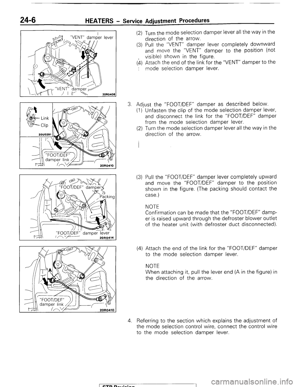
(2) Turn the mode selection damper lever all the way in the
direction of the arrow.
(3) Pull the “VENT” damper lever completely downward
and move the “VENT” damper to the position (not
visible) shown in the figure.
(4) Attach the end of the link for the “VENT” damper to the
: mode selection damper lever.
3. Adjust the “FOOT/DEF” damper as described below.
(1) Unfasten the clip of the mode selection damper lever,
and disconnect the link for the “FOOT/DEF” damper
from the mode selection damper lever.
(2) Turn the mode selection damper lever all the way in the
direction of the arrow.
(3) Pull the “FOOT/DEF” damper lever completely upward
and move the “FOOT/DEF” damper to the position
shown in the figure. (The packing should contact the
case.)
NOTE
Confirmation can be made that the “FOOT/DEF” damp-
er is raised upward through the defroster blower outlet
of the heater unit (with defroster duct disconnected).
(4) Attach the end of the link for the “FOOT/DEF” damper
to the mode selection damper lever.
NOTE
When attaching it, pull the lever end (A in the figure) in
the direction of the arrow.
4. Referring to the section which explains the adjustment of
the mode selection control wire, connect the control wire
to the mode selection damper lever.
1 STB Revision