1987 MAZDA 626 radiator
[x] Cancel search: radiatorPage 638 of 1865

EGR SYSTEM (UNLEADED FUEL) 4C
EXHAUST GAS RECIRCULATION
(EGR)
SYSTEM (UNLEADED FUEL)
This system introduces exhaust gas into the intake manifold to reduce NOx emissions. It operates de-
pending on the engine load, engine speed (1,500—3,500 rpm), engine coolant temperature (above
70°C, 158°F), and radiator coolant temperature (above 17°C, 63°F).
COMPONENT DESCRIPTION
Component Function Remark
EGR control valve Recirculates portion of exhaust gas
EGR modulator valve Controls vacuum acting on EGR control valve
Engine control unit Detects signals from input sensors and switches; con-trols solenoid valve (EGR)
Ne signal pick-up Detects crank angle at 180° intervals; sends signal to engine control unit
Solenoid valve (EGR) Controls vacuum to EGR control valve
Throttle sensor Detects throttle valve opening angle; sends signal to en-
gine control unit
Installed on throttle body
Water thermo sensor Detects coolant temperature; sends signal to engine control unit
Water thermo switch Detects radiator coolant temperature; sends signal to engine control unit ON: above 17°C (63°F)
76G04C-143
AC—17
Page 653 of 1865

4C CONTROL SYSTEM
RELATIONSHIP CHART
Output Devices
and
Input Devices (Unleaded fuel)
IGNITION SWITCH
(ON POSION) X X X X X O X X X X X X X X O
TEST CONNECTOR X X X O X X X X X X X X X O X
ELECTRICAL LOAD CONTROL UNIT X X X o X X X X X X X X X X X
P/S PRESSURE SWITCH X X X o X X X X X X X X X X X
A/C SWITCH X X X o X X X X X X X X O X X
IGNITION SWITCH
(STA POSITION) O O X o O X X X X O X X X O X
NEUTRAL
AND
CLUTCH SWITCH O X X o X X X X X X X X X X X
OXYGEN SENSOR o X X X X X X X X X X X X X X
WATER THERMO
SWITCH (RADIATOR) o X X X X X X X o X X X X X X
INTAKE
AIR
THERMO SENSOR X X X X X X X X X O X X X X X
WATER
THERMO SENSOR o X X o X X o o O O X X X O o
IDLE SWITCH o X X o X X X X X o X X X O X
THROTTLE SENSOR o X X X X X X X O X X X X o X
AIR FLOW SENSOR o X X X X X X o X X X X X o O
Ne SIGNAL o o X O o X X O O O o o X o O
G SIGNAL X O X X X X X X X X X X X X X
\
INPUT
DEVICE
OUTPUT
DEVICE
FUEL
INJECTION
AMOUNT FUEL
INJECTION
TIMING
AIR
VALVE
ISC
VALVE
FUEL
PUMP
CONTROL
MAIN
POWER
CONTROL
SOLENOID
VALVE
(No.1
PURGE)
SOLENOID
VALVE
(No.2
PURGE)
SOLENOID
VALVE
(EGR)
SOLENOID
VALVE
(PRESSURE
REGULATOR
CONTROL)
SOLENOID
VALVE
(VARIABLE
INERTIA
CONTROL)
OXYGEN
SENSOR
RELAY
I A/C
RELAY
IGNITER
AIR
FLOW
SENSOR
(BURN-OFF)
\
INPUT
DEVICE
OUTPUT
DEVICE
INJECTOR
BAC
VALVE
CONTROL
RELAY
SOLENOID
VALVE
(No.1
PURGE)
SOLENOID
VALVE
(No.2
PURGE)
SOLENOID
VALVE
(EGR)
SOLENOID
VALVE
(PRESSURE
REGULATOR
CONTROL)
SOLENOID
VALVE
(VARIABLE
INERTIA
CONTROL)
OXYGEN
SENSOR
RELAY
I A/C
RELAY
IGNITER
AIR
FLOW
SENSOR
(BURN-OFF)
76G04C-167
4C—92
Page 660 of 1865

CONTROL SYSTEM 4C
Terminal Voltage
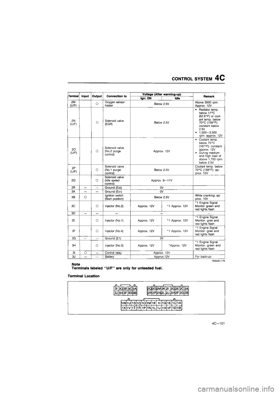
If the input and output devices wiring are normal, but the engine control unit terminal voltage is incor-
rect, replace the engine control unit.
Terminal Input Output Connection to Voltage (After warming-up) Remark Terminal Input Output Connection to Ign: ON Idle Remark
1A — — — — — —
1B o Self-Diagnosis Checker (Code No.)
For 3sec. after ignition switch OFF ->• ON: below 2.5V (Buzzer sounds) After 3sec.: approx. 12V (Buzzer does not sound)
• Using Self-Diagnosis Check-er and test con-nector grounded • Buzzer sounds: below 2.5V • Buzzer does not sound: approx. 12V
1C o
Solenoid valve (Variable inertia control) Approx. 12V
Above 5200 rpm (Unleaded fuel) or 5400 rpm (Leaded fuel): Below 2.5V
1D o Self-Diagnosis Checker (Monitor lamp)
For 3sec.after igni-tion switch OFF -» ON:
approx. 5V (light il-luminates)
After 3sec.: approx. 12V (light does not illuminate)
(Test connector grounded) approx. 5V (Test connector not grounded) Monitor lamp ON: approx. 5V Monitor lamp OFF: approx. 12V
With Self-Diagnosis
Checker
1E O Idle switch Accelerator pedal released: OV
Accelerator pedal depressed: approx. 12V
1F o A/C relay A/C switch ON: below 2.5V
A/C switch OFF: approx. 12V Blower motor ON
1G O Neutral or clutch switch
In-gear condition Clutch pedal depressed: approx. 12V Clutch pedal released: OV
MTX (Neutral: con-stant approx. 12V)
1H
(U/F) o Water thermo
switch
Approx. 12V Radiator temp.: be-low 17°C (63°R 1H
(U/F) o Water thermo
switch OV Radiator temp.:
above 17°C (63°F)
11 o Electrical load control unit E/L switch ON: below 2.5V
E/L switch OFF: approx. 10—12V
Electrical load: Rear defroster switch
Headlight switch Blower motor switch (3rd & 4th position) Electrical fan switch
1J — — — — —
1K o P/S pressure
switch
Constant approx.
12V
P/S ON: below 2.5V P/S OFF: approx. 12V
1L o A/C switch A/C switch ON: below 2.5V A/C switch OFF: aDDrox. 12V Blower motor: ON
1M o Distributor
(Ne signal) OV or 5V Approx. 2.0V
1N o Distributor (G signal) OV or 5V Approx. 1.2V
Note
Terminals labeled "U/F" are only for unleaded fuel.
4C-99
Page 662 of 1865

CONTROL SYSTEM 4C
Terminal Input Output Connection to Voltage (After warming-up) Remark Terminal Input Output Connection to Ign: ON Idle Remark
2M
(U/F) o Oxygen sensor
heater Below 2.5V Above 3000 rpm: Approx. 12V
2N
(U/F) o Solenoid valve (EGR) Below 2.5V
• Radiator temp, below 17°C (62.6°F) or cool-ant temp, below 70°C (158°F): constant below 2.5 V
• 1,500-3,500 rpm: approx. 12V
20 (U/F) 0 Solenoid valve (No.2 purge control) Approx. 12V
• Coolant temp, below 75 °C (167°F): constant approx. 12V
• During medium and high load of above 1,700 rpm: below 2.5V
2P
(U/F) o
Solenoid valve
(No.1 purge
control)
Below 2.5V
Coolant temp, below 70°C (158°F): ap-prox. 12V
2Q o Solenoid valve (Idle speed control) Approx. 9—11V
2R — — Ground (E02) OV
3A — — Ground (E01) OV
3B O Ignition switch
(Start position) Below 2.5V While cranking: ap-
Drox. 10V
3C o Injector (No.2) Approx. 12V *1 Approx. 12V
*1 Engine Signal Monitor green and red liahts flash
3D — — — — —
3E o Injector (No.1) Approx. 12V *1 Approx. 12V
*1 Engine Signal
Monitor: gree and
red liahts flash
3F 0 Injector (No.4) Approx. 12V *1 Approx. 12V
*1 Engine Signal Monitor: gree and red liahts flash
3G — Ground (E1) OV
3H o Injector (No.3) Approx. 12V 'Approx. 12V *1 Engine Signal
Monitor: green and
red lights flash
31 0 — Control relav ADDrox. 12V
3J — — Battery Approx. 12V For back-uD
76G04C-179
Note
Terminals labeled "U/F" are only for unleaded fuel.
Terminal Location
31 3G 3E 3C 3A
3J 3H 3F 3D 3B
2Q 2d 2M *
L
2G 2E 2C <
CM
2R 2P 2N 2L 2J 2H 2F 20 2B
1W 1U 1S 1Q 10 1M 1K 11 1G 1E 1C 1A
1X 1V 1T 1R 1P 1N 1L 1J 1H 1F 1D 1B
4C-101
Page 667 of 1865

4C CONTROL SYSTEM
4. Make sure that the throttle valve is fully closed.
5. Turn the throttle sensor so that the BLUE wire volt-
age indicates within the specified closed range.
6. Tighten the throttle sensor mounting screw.
7. Recheck that the BLUE wire voltage is within the
specified range.
76G04C-195
8. Turn the ignition switch OFF.
9. Disconnect the SST and reconnect the throttle sen-
sor connector.
10. Disconnect the negative battery terminal and de-
press the brake pedal for 5 seconds to eliminate
the from the malfunction memory from the control
unit.
76G04C-196
76G04C-198
4C-106
IDLE SWITCH
Inspection
1. Disconnect the idle switch connector.
2. Check continuity between the switch and a ground.
Throttle valve condition Continuity
Fully closed Yes
Open No
3. If not correct, check condition of the wiring harness
of the idle switch. Replace the idle switch and throt-
tle body as an assembly, if necessary.
WATER THERMO SWITCH
Inspection
1. Remove the switch from the radiator.
2. Place the switch in water with a thermometer and
heat the water gradually.
3. Check for continuity of the switch with an
ohmmeter.
Coolant temp. Continuity
More than approx. 17°C (63°F) Yes
Less than approx. 10°C (63°F) No
4. If not correct, replace the water thermo switch.
Page 786 of 1865

5 QUICK START SYSTEM (QSS)
Glow plug relay GLOW PLUG RELAY
Inspection
1. As shown in the figure, connect the battery and
an ohmmeter to the relay.
2.
If
the ohmmeter shows continuity when the battery
is connected, and no continuity when the battery
is disconnected, the relay is good.
3. Replace the relay if it fails this test.
4BG05X-123
GLOW PLUG
Inspection
1. Check the continuity between the positive termi-
nal of the glow plug and cylinder head with a cir-
cuit tester.
2. If there is no continuity, replace the glow plug.
4BG05X-121
Removal
Remove in the following order:
1. Glow plug connector attaching nut.
2. Glow plug connector.
3. Glow plug
Installation
Install the glow plug, reverse order of removal.
76G05X-053
63G05X-336
5-80
WATER TEMPERATURE SWITCH
Removal
Remove the water temperature switch from the
radiator.
Installation
Install in the reverse order of removal.
Inspection
1. Place the water temperature switch in water with
a thermometer and heat the water gradually.
2. Check the temperature at which continuity exists
between the terminals.
3. Replace the switch, if necessary.
Specified temperature: above 28—32°C
(82—90°F)
Page 1552 of 1865

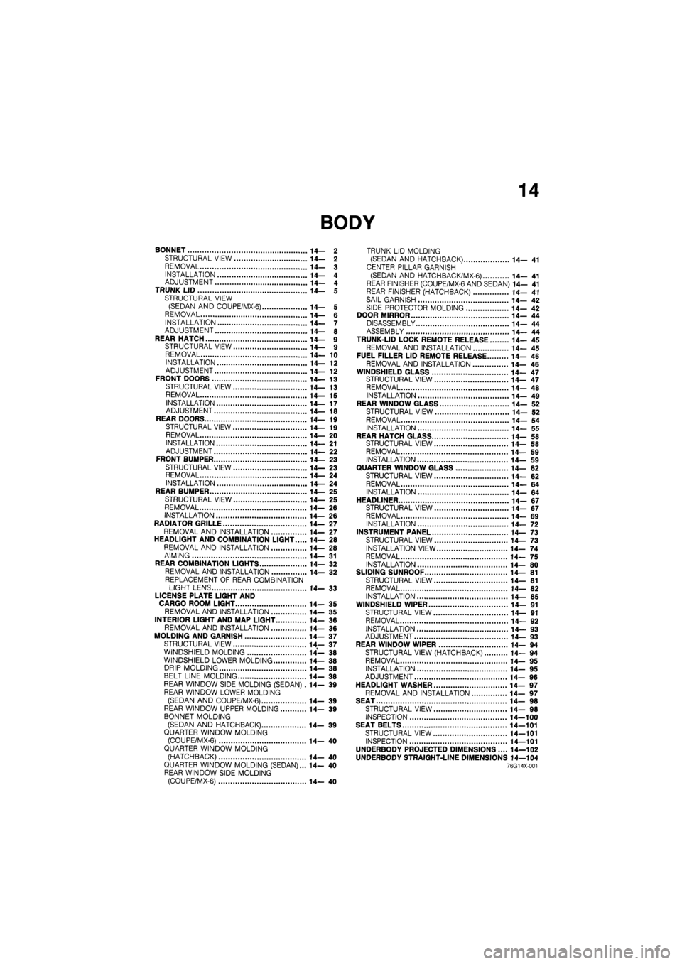
14
BONNET 14— 2
STRUCTURAL VIEW 14— 2
REMOVAL 14— 3
INSTALLATION 14— 4 ADJUSTMENT 14— 4 TRUNK LID 14— 5 STRUCTURAL VIEW (SEDAN AND COUPE/MX-6) 14— 5 REMOVAL 14— 6 INSTALLATION 14— 7 ADJUSTMENT 14— 8
REAR HATCH 14— 9 STRUCTURAL VIEW 14— 9 REMOVAL 14— 10 INSTALLATION 14— 12 ADJUSTMENT 14— 12 FRONT DOORS 14—13
STRUCTURAL VIEW 14— 13
REMOVAL 14—15
INSTALLATION 14—17 ADJUSTMENT 14— 18 REAR DOORS 14—19 STRUCTURAL VIEW 14— 19 REMOVAL 14— 20
INSTALLATION 14— 21 ADJUSTMENT 14— 22 FRONT BUMPER 14— 23
STRUCTURAL VIEW 14—23 REMOVAL 14— 24 INSTALLATION 14—24 REAR BUMPER 14— 25
STRUCTURAL VIEW 14— 25 REMOVAL 14— 26
INSTALLATION 14— 26 RADIATOR GRILLE 14— 27 REMOVAL AND INSTALLATION 14— 27 HEADLIGHT AND COMBINATION LIGHT 14— 28 REMOVAL AND INSTALLATION 14— 28
AIMING 14— 31 REAR COMBINATION LIGHTS 14— 32 REMOVAL AND INSTALLATION 14— 32
REPLACEMENT OF REAR COMBINATION LIGHT LENS 14— 33
LICENSE PLATE LIGHT AND CARGO ROOM LIGHT 14— 35 REMOVAL AND INSTALLATION 14— 35
INTERIOR LIGHT AND MAP LIGHT 14- 36 REMOVAL AND INSTALLATION 14— 36
MOLDING AND GARNISH 14— 37
STRUCTURAL VIEW 14— 37 WINDSHIELD MOLDING 14— 38 WINDSHIELD LOWER MOLDING 14— 38 DRIP MOLDING 14— 38 BELT LINE MOLDING 14— 38 REAR WINDOW SIDE MOLDING (SEDAN) .14— 39 REAR WINDOW LOWER MOLDING
(SEDAN AND COUPE/MX-6) 14— 39 REAR WINDOW UPPER MOLDING 14— 39
BONNET MOLDING
(SEDAN AND HATCHBACK) 14— 39 QUARTER WINDOW MOLDING (COUPE/MX-6) 14— 40 QUARTER WINDOW MOLDING
(HATCHBACK) 14—40 QUARTER WINDOW MOLDING (SEDAN)... 14— 40 REAR WINDOW SIDE MOLDING (COUPE/MX-6) 14— 40
TRUNK LID MOLDING (SEDAN AND HATCHBACK) 14— 41
CENTER PILLAR GARNISH
(SEDAN AND HATCH BAC K/MX-6) 14— 41 REAR FINISHER (COUPE/MX-6 AND SEDAN) 14— 41 REAR FINISHER (HATCHBACK) 14— 41
SAIL GARNISH 14— 42
SIDE PROTECTOR MOLDING 14— 42 DOOR MIRROR 14— 44 DISASSEMBLY 14— 44 ASSEMBLY 14— 44 TRUNK-LID LOCK REMOTE RELEASE 14— 45 REMOVAL AND INSTALLATION 14— 45 FUEL FILLER LID REMOTE RELEASE 14— 46
REMOVAL AND INSTALLATION 14— 46 WINDSHIELD GLASS 14—47 STRUCTURAL VIEW 14—47 REMOVAL 14— 48 INSTALLATION 14— 49 REAR WINDOW GLASS 14— 52
STRUCTURAL VIEW 14— 52 REMOVAL 14— 54
INSTALLATION 14— 55 REAR HATCH GLASS 14— 58 STRUCTURAL VIEW 14— 58 REMOVAL 14— 59 INSTALLATION 14— 59 QUARTER WINDOW GLASS 14— 62 STRUCTURAL VIEW 14— 62
REMOVAL 14— 64 INSTALLATION 14—64
HEADLINER 14- 67 STRUCTURAL VIEW 14—67 REMOVAL 14— 69 INSTALLATION 14— 72 INSTRUMENT PANEL 14— 73 STRUCTURAL VIEW 14— 73
INSTALLATION VIEW 14— 74
REMOVAL 14— 75 INSTALLATION 14— 80 SLIDING SUNROOF 14— 81 STRUCTURAL VIEW 14— 81 REMOVAL 14— 82 INSTALLATION 14— 85 WINDSHIELD WIPER 14— 91
STRUCTURAL VIEW 14— 91
REMOVAL 14— 92
INSTALLATION 14— 93 ADJUSTMENT 14— 93 REAR WINDOW WIPER 14—94 STRUCTURAL VIEW (HATCHBACK) 14— 94 REMOVAL 14— 95 INSTALLATION 14—95 ADJUSTMENT 14— 96
HEADLIGHT WASHER 14— 97 REMOVAL AND INSTALLATION 14— 97 SEAT 14— 98 STRUCTURAL VIEW 14— 98 INSPECTION 14—100 SEAT BELTS 14—101
STRUCTURAL VIEW 14—101 INSPECTION 14—101
UNDERBODY PROJECTED DIMENSIONS.... 14—102 UNDERBODY STRAIGHT-LINE DIMENSIONS 14—104 76G14X-001
Page 1578 of 1865

RADIATOR
GRILLE 1
4
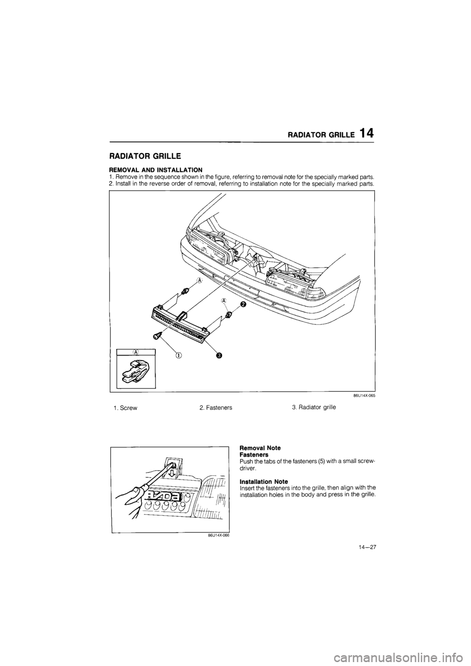
RADIATOR GRILLE
REMOVAL AND INSTALLATION
1. Remove in the sequence shown in the figure, referring to removal note for the specially marked parts.
2. Install in the reverse order of removal, referring to installation note for the specially marked parts.
86U14X-065
1. Screw 2. Fasteners 3. Radiator grille
Removal Note
Fasteners
Push the tabs of the fasteners (5) with a small screw-
driver.
Installation Note
Insert the fasteners into the grille, then align with the
installation holes in the body and press in the grille.
86U14X-066
14—27