Page 1579 of 1865
1 4 HEADLIGHT AND COMBINATION LIGHT
HEADLIGHT AND COMBINATION LIGHT
REMOVAL AND INSTALLATION
1. Disconnect the negative battery cable.
2. Remove in the sequence shown in the figure, referring to removal note for the specially marked parts.
3. Install in the reverse order of removal.
76G14X-005
1. Screw
2. Turn signal light assembly
3. Screw
4. Radiator grille
5. Bolts
6. Bolts
7. Headlight assembly
8. Screws
9. Light garnish
10. Headlight bulb
60 + 55W/55W
11. Parking light bulb 5W
12. Turn signal light bulb
21W
14—28
Page 1580 of 1865
HEADLIGHT AND COMBINATION LIGHT 1 4
76G14X-006
1. Screw 6. Bolts
2. Turn signal light assembly 7. Fastener
3. Screw 8. Screw
4. Radiator grille 9. Light garnish
5. Bolts 10. Headlight assembly
11. Headlight bulb
60 + 55/55W
12. Parking light bulb 5W
13. Turn signal light bulb
21W
14—29
Page 1807 of 1865
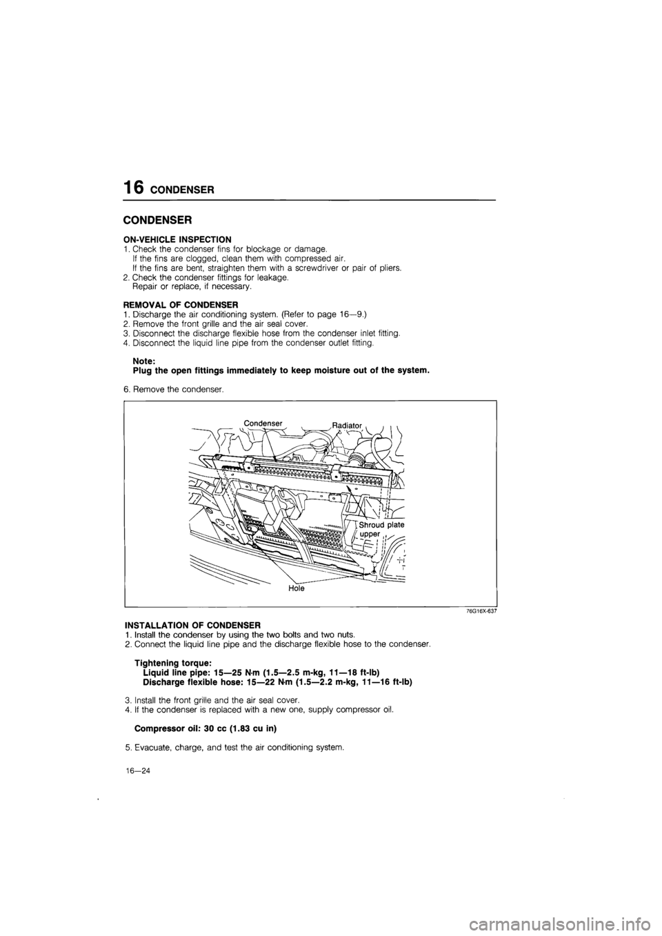
16 CONDENSER
CONDENSER
ON-VEHICLE INSPECTION
1. Check the condenser fins for blockage or damage.
If the fins are clogged, clean them with compressed air.
If the fins are bent, straighten them with a screwdriver or pair of pliers.
2. Check the condenser fittings for leakage.
Repair or replace, if necessary.
REMOVAL OF CONDENSER
1. Discharge the air conditioning system. (Refer to page 16—9.)
2. Remove the front grille and the air seal cover.
3. Disconnect the discharge flexible hose from the condenser inlet fitting.
4. Disconnect the liquid line pipe from the condenser outlet fitting.
Note:
Plug the open fittings immediately to keep moisture out of the system.
6. Remove the condenser.
Condenser Radiator
Hole
76G16X-637
INSTALLATION OF CONDENSER
1. Install the condenser by using the two bolts and two nuts.
2. Connect the liquid line pipe and the discharge flexible hose to the condenser.
Tightening torque:
Liquid line pipe: 15—25 Nm (1.5—2.5 m-kg, 11—18 ft-lb)
Discharge flexible hose: 15—22 N-m (1.5—2.2 m-kg, 11—16 ft-lb)
3. Install the front grille and the air seal cover.
4. If the condenser is replaced with a new one, supply compressor oil.
Compressor oil: 30 cc (1.83 cu in)
5. Evacuate, charge, and test the air conditioning system.
16—24
Page 1830 of 1865
30 TECHNICAL DATA
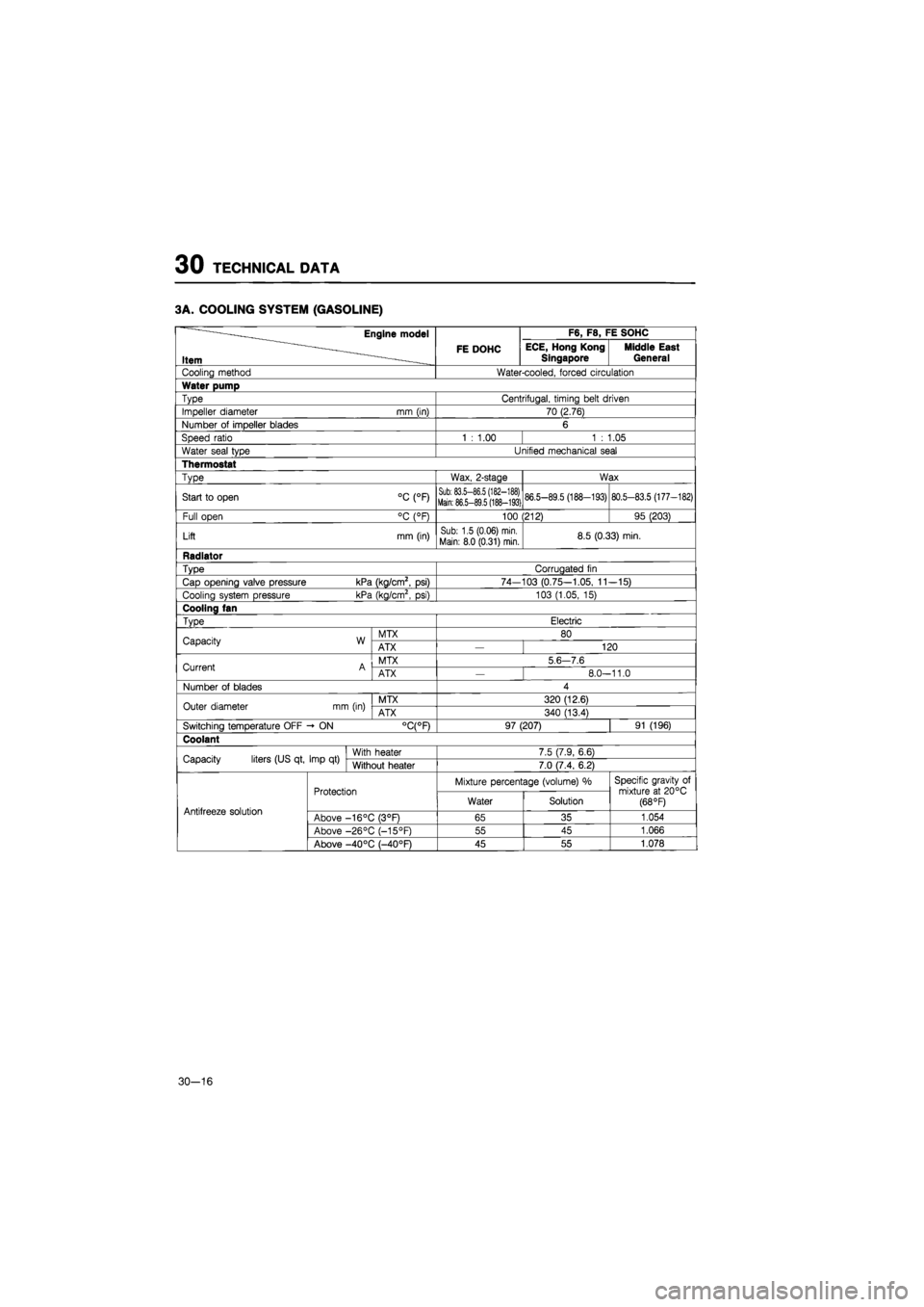
3A. COOLING SYSTEM (GASOLINE)
Engine model F6, F8, FE SOHC
Item FE DOHC ECE, Hong Kong
Singapore Middle East General
Cooling method Water-cooled, forced circulation
Water pump
Type Centrifugal, timing belt driven
Impeller diameter mm (in) 70 (2.76)
Number
of
impeller blades 6
Speed ratio 1
:
1.00 1
:
1.05
Water seal type Unified mechanical seal
Thermostat
Type Wax, 2-stage Wax
Start
to
open °C (°F) Sub: 83.5-86.5 (182-188) Main: 86.5-89.5 (188-193) 86.5-89.5 (188-193) 80.5-83.5 (177-182)
Full open °C (°F) 100 (212) 95 (203)
Lift mm (in) Sub: 1.5 (0.06) min.
Main: 8.0 (0.31) min. 8.5 (0.33) min.
Radiator
Type Corrugated
fin
Cap opening valve pressure kPa (kg/cm2,
psi)
74-103 (0.75-1.05,
11
-15)
Cooling system pressure kPa (kg/cm2,
psi)
103 (1.05,
15)
Cooling fan
Type Electric
Capacity W MTX 80 Capacity W ATX 120
Current A MTX 5
6 7.6
Current A ATX
—
8.0-11.0
Number
of
blades 4
Outer diameter mm (in) MTX 320 (12.6) Outer diameter mm (in) ATX 340 (13.4)
Switching temperature OFF -
ON
°C(°F) 97 (207) 91 (196)
Coolant
Capacity liters (US qt, Imp
qt)
With heater 7.5 (7.9, 6.6) Capacity liters (US qt, Imp
qt)
Without heater 7.0 (7.4, 6.2)
Protection Mixture percentage (volume)
%
Specific gravity
of
mixture
at
20°C (68 °F) Antifreeze solution
Protection Water Solution
Specific gravity
of
mixture
at
20°C (68 °F) Antifreeze solution Above -16°C (3°F) 65 35 1.054
Above -26°C (-15°F) 55 45 1.066
Above -40 °C (—40°F) 45 55 1.078
30-16
Page 1831 of 1865
TECHNICAL DATA 30
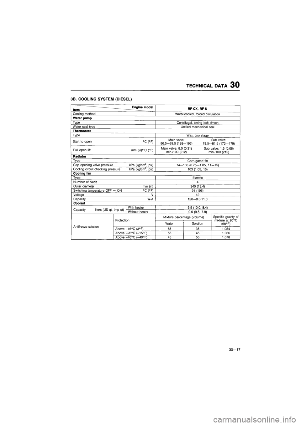
3B. COOLING SYSTEM (DIESEL)
Item Engine model RF-CX, RF-N
Cooling method Water-cooled, forced circulation
Water pump
Type Centrifugal, timing belt driven
Water seal type Unified mechanical seal
Thermostat
Type Wax, two stage
Start
to
open °C (°F) Main valve:
86.5-89.5 (188-193)
78.5-
Sub valve: 81.5 (173-179)
Full open lift mm (in)/°C (°F) Main valve: 8.0 (0.31) Sub valve: 1.5 (0.06) min./100 (212) min./100 (212)
Radiator
Type Corrugated
fin
Cap opening valve pressure kPa (kg/cm2,
psi)
74—103 (0.75—1.05,
11
-15)
Cooling circuit checking pressure kPa (kg/cm2,
psi)
103 (1.05,
15)
Cooling fan
Type Electric
Number
of
blade 4
Outer diameter mm (in) 340 (13.4)
Switching temperature OFF -»
ON
°C (°F) 91 (196)
Voltage V 12
Capacity W-A 120-8.0-11.0
Coolant
Capacity liters (US qt, Imp
qt)
With heater 9.5 (10.0, 8.4) Capacity liters (US qt, Imp
qt)
Without heater 9.0 (9.5, 7.9)
Protection Mixture percentage (Volume) Specific gravity
of
mixture
at
20°C (68 °F) Antifreeze solution
Protection Water Solution
Specific gravity
of
mixture
at
20°C (68 °F) Antifreeze solution Above -16°C (3°F) 65 35 1.054
Above -26°C (-15°F) 55 45 1.066
Above -40°C (-40°F) 45 55 1.078
30-17
Page 1834 of 1865
30 TECHNICAL DATA
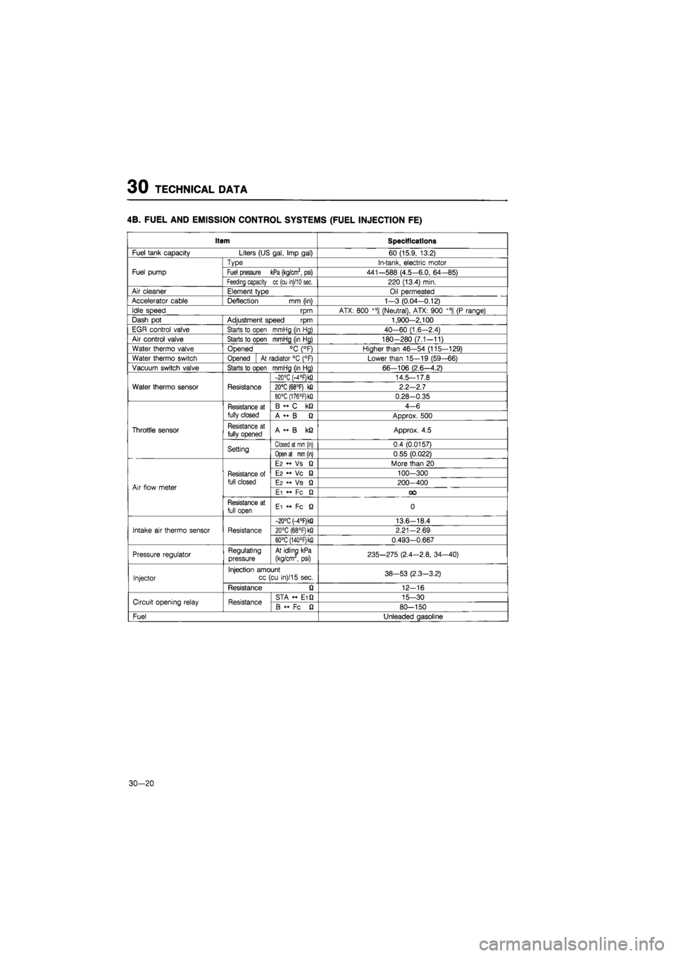
4B. FUEL AND EMISSION CONTROL SYSTEMS (FUEL INJECTION FE)
Item Specifications
Fuel tank capacity Liters (US gal, Imp gal) 60 (15.9, 13.2)
Fuel pump
Type In-tank, electric motor
Fuel pump Fuel pressure kPa (kg/cm2, psi) 441-588 (4.5-6.0, 64-85) Fuel pump
Feeding capacity cc (cu in)/10 sec. 220 (13.4) min.
Air cleaner Element type Oil permeated
Accelerator cable Deflection
mm
(in) 1—3 (0.04-0.12)
Idle speed
rpm
ATX: 800 +58 (Neutral), ATX: 900 +600
(P
range)
Dash
pot
Adjustment speed
rpm
1,900-2.100
EGR control valve Starts
to
open mmHg (in Hg) 40-60 (1.6-2.4)
Air control valve Starts
to
open mmHg (in Hg) 180-280 (7.1-11)
Water thermo valve Opened
°C
(°F) Higher than 46—54 (115-129)
Water thermo switch Opened
At
radiator
°C
(°F) Lower than 15—19 (59—66)
Vacuum switch valve Starts to open mmHg (in Hg) 66—106 (2.6—4.2)
Water thermo sensor Resistance
-20°C (-4°F)k!) 14.5-17.8
Water thermo sensor Resistance 20°C (68°F)
kQ
2.2-2.7 Water thermo sensor Resistance
80°C (176°F)k!i 0.28-0.35
Throttle sensor
Resistance
at
fully closed
B
C kQ
4-6
Throttle sensor
Resistance
at
fully closed A
« B Q
Approx.
500
Throttle sensor Resistance
at
fully opened A
«• B kQ
Approx.
4.5
Throttle sensor
Setting Closed at mm (in) 0.4 (0.0157)
Throttle sensor
Setting Open at mm (in) 0.55 (0.022)
Air flow meter
Resistance
of
full closed
E2 « Vs fi
More than
20
Air flow meter
Resistance
of
full closed
E2 •+ Vc 0
100-300
Air flow meter
Resistance
of
full closed
E2 VB Q
200-400 Air flow meter
Resistance
of
full closed
Ei
•+ Fc Q OO
Air flow meter
Resistance
at
full open Ei
•+ Fc Q
0
Intake
air
thermo sensor Resistance
-20°C M°RkQ 13.6-18.4
Intake
air
thermo sensor Resistance 20°C (68°F) kfi 2.21—2.69 Intake
air
thermo sensor Resistance
60°C (140°RkQ 0.493-0.667
Pressure regulator Regulating pressure At idling kPa
(kg/cm
,
psi) 235-275 (2.4—2.8, 34-40)
Injector
Injection amount cc (cu in)/15 sec. 38-53 (2.3-3.2) Injector
Resistance
Q
12-16
Circuit opening relay Resistance STA Ei Q 15-30 Circuit opening relay Resistance B
Fc fi
80-150
Fuel Unleaded gasoline
30-20
Page 1857 of 1865
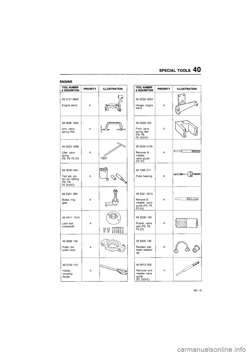
SPECIAL TOOLS 40
ENGINE
TOOL NUMBER & DESCRIPTION PRIORITY ILLUSTRATION
49 0107 680A
Engine stand A
V
ir==JJ
i
49 0636 100A
Arm, valve
spring lifter
A \JL
JL
49 0223 105B
Lifter, valve spring
(F6, F8, FE-2V)
A
49 G030 040
Tool set,
pis-
ton pin setting (F6,
F8,
FE SOHC)
A
49 E301
060
Brake, ring
gear
A
J
49 H011 101A
Lock tool,
crankshaft
A
ft
im
49 0636
145
Puller,
fan
puller boss A
49 S120 710
Holder, coupling
flange
A
TOOL NUMBER & DESCRIPTION PRIORITY ILLUSTRATION
49 G030 005A
Hanger, engine stand A
|i
l\fy ^
49 G030 222
Pivot, valve spring lifter (F6,
F8,
FE SOHC)
A
r
o
49 0249 01 OA
Remover
&
installer, valve guide (FE-3V)
A
49 0249 01 OA
Remover
&
installer, valve guide (FE-3V)
A
c ii&zm
49 0249 01 OA
Remover
&
installer, valve guide (FE-3V)
A
49 1285 071
Puller bearing A
49 0221 251A
Remove
&
installer, valve
guide (F6,
F8,
FE-2V)
A
cr-
49 G030
160
Pusher, valve
seal (F6,
F8,
FE-2V)
A
if !
49 9200
146
Radiator cap tester adaptor set
A
49 B012 005
Remover and installer valve guide
(FE DOHC)
A
40—3
Page 1858 of 1865
40 SPECIAL TOOLS
TOOL NUMBER & DESCRIPTION PRIORITY ILLUSTRATION
49 S120 220
Holder, tappet
(Disel)
A
49 0636 165A
Remover
&
installer,
valve guide
(Diesel)
A i
1 vrn
49 0223
061
Remover
&,
installer, piston pin (RF-N, FE DOHC)
B
49 S120 215A
Pulley puller (Diesel)
A
49 V101 060A
Brake,
ring gear
(Diesel)
A
49 S120 222
Pivot, valve spring lifter (RF-N, RF-CX, FE DOHC)
A
49 G011
101
Lock tool, crankshaft (RF-N, RF-CX)
A
49 H012 009
Pusher, valve
seal
(FE-3V)
A
40-4
TOOL NUMBER & DESCRIPTION PRIORITY ILLUSTRATION
49 9200
147
Radiator cap tester adaptor set
A
49 S120 170
Remover, valve seal (RF-N, RF-CX, FE DOHC)
A
49 0552
165
Remover
&
installer, valve guide (Diesel)
A D
<-—j
nm
49 S120 105
Compressor, valve spring (Diesel)
A
S-tSfe
49 S120 105
Compressor, valve spring (Diesel)
A
49 S120 160
Pusher, valve
seal
(Diesel)
A
49 G012 001
Collar (FE DOHC) A
( 4
49 G012 002
Pusher, valve seal (FE DOHC)
A
49 G011
001
Replacer,
piston
pin
(RF-CX)
A