Page 1334 of 1865
1 0 4-WHEEL STEERING GEAR AND LINKAGE
86U10X-085
Rear Steering Gear and Linkage
1. Check the following and replace the rear steering
gear assembly if necessary.
(a) Damaged or cracked case
(b) Faulty stepper motor or rear-to-front steering
ratio sensor
(c) Sticking bearings
(d) Oil leakage
Note
There is no fluid in a new replacement rear
steering gear assembly, add fluid to the spe-
cified level. (Refer to 10—12.)
2. Check and tighten bolts and nuts, if necessary.
3. Check the following and replace any faulty parts.
(a) Cracked, damaged, or deteriorated rear stee-
ring gear boots and bands
(b) Cracked or damaged oil pan
(c) Malfunctioning solenoid valve
86U10X-086
10-46
Page 1385 of 1865
ELECTRICAL COMPONENTS OF 4-WHEEL STEERING 1 0
Warning light output pattern Malfunction Flow chart No.
ON
ncc
Stepper motor or wiring harness 4WS—6 Stepper motor or wiring harness 4WS—6
ON
r\cc
Oil leakage or oil
level switch
4WS—7 Oil leakage or oil
level switch
4WS—7
ON
OFF
Control unit 4WS—8 Control unit 4WS—8
ON
ncc
Control unit, alter-nator, or wiring harness
4WS—9
ON
ncc
Control unit, alter-nator, or wiring harness
4WS—9 Control unit, alter-nator, or wiring harness
4WS—9
86U10X-226
10—97
Page 1391 of 1865

ELECTRICAL COMPONENTS OF 4-WHEEL STEERING 1 0
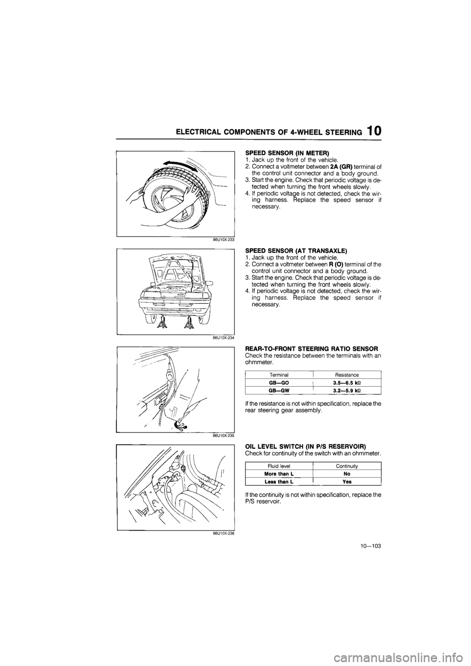
SPEED SENSOR (IN METER)
1. Jack up the front of the vehicle.
2. Connect a voltmeter between 2A (GR) terminal of
the control unit connector and a body ground.
3. Start the engine. Check that periodic voltage is de-
tected when turning'the front wheels slowly.
4. If periodic voltage is not detected, check the wir-
ing harness. Replace the speed sensor if
necessary.
86U10X-233
SPEED SENSOR (AT TRANSAXLE)
1. Jack up the front of the vehicle.
2. Connect a voltmeter between R (O) terminal of the
control unit connector and a body ground.
3. Start the engine. Check that periodic voltage is de-
tected when turning the front wheels slowly.
4. If periodic voltage is not detected, check the wir-
ing harness. Replace the speed sensor if
necessary.
86U10X-234
REAR-TO-FRONT STEERING RATIO SENSOR
Check the resistance between the terminals with an
ohmmeter.
Terminal [ Resistance
GB—GO l 3.5—6.5 kfi
GB—GW ' 3.2—5.9 kfi
If
the resistance is not within specification, replace the
rear steering gear assembly.
86U10X-235
OIL LEVEL SWITCH (IN P/S RESERVOIR)
Check for continuity of the switch with an ohmmeter.
Fluid level Continuity
More than L No
Less than L Yes
If
the continuity is not within specification, replace the
P/S reservoir.
86U10X-236
10—103
Page 1690 of 1865
WARNING LIGHT AND SENDER 1 5
Washer Fluid Low Level Warning Light
76G15X-039
76G15X-040
Engine Oil Pressure Warning Light
76G15X-041
15—35
Page 1695 of 1865
15 WARNING AND SENDER
86U15X-068
86U15X069
86U15X-070
Door Switch
1. Check for continuity of the switch with an
ohmmeter.
2. If continuity is not as specified, replace the switch.
Washer Level Sensor
1. Check for continuity between C (LY) terminal and
D (B) terminal of the washer level sensor con-
nector.
Oil Pressure Switch
1. Disconnect the connector from the oil pressure
switch.
2. Check for continuity between the switch and a
body ground with each condition.
Coolant Level Sensor
1. Remove the level sensor and connect the con-
nector.
2. With the sensor not grounded to the body, start
the engine.
3. After checking that the warning light illuminates,
ground the threaded part of the sensor.
4. If the warning light remains illuminated, the sen-
sor is faulty and replace it.
73G15X-013
15—40
Engine Continuity
Running Yes
Stop No
Terminals Float level Continuity
C (LY)—D
(B)
Bottom Yes C (LY)—D
(B)
Above bottom No
2. If continuity is not as specified, replace the sensor.
Page 1796 of 1865

COMPRESSOR 16
69G16X-026
M10X1.25^45
Low-pressure x pressure
hose hose Compressor
COMPRESSOR
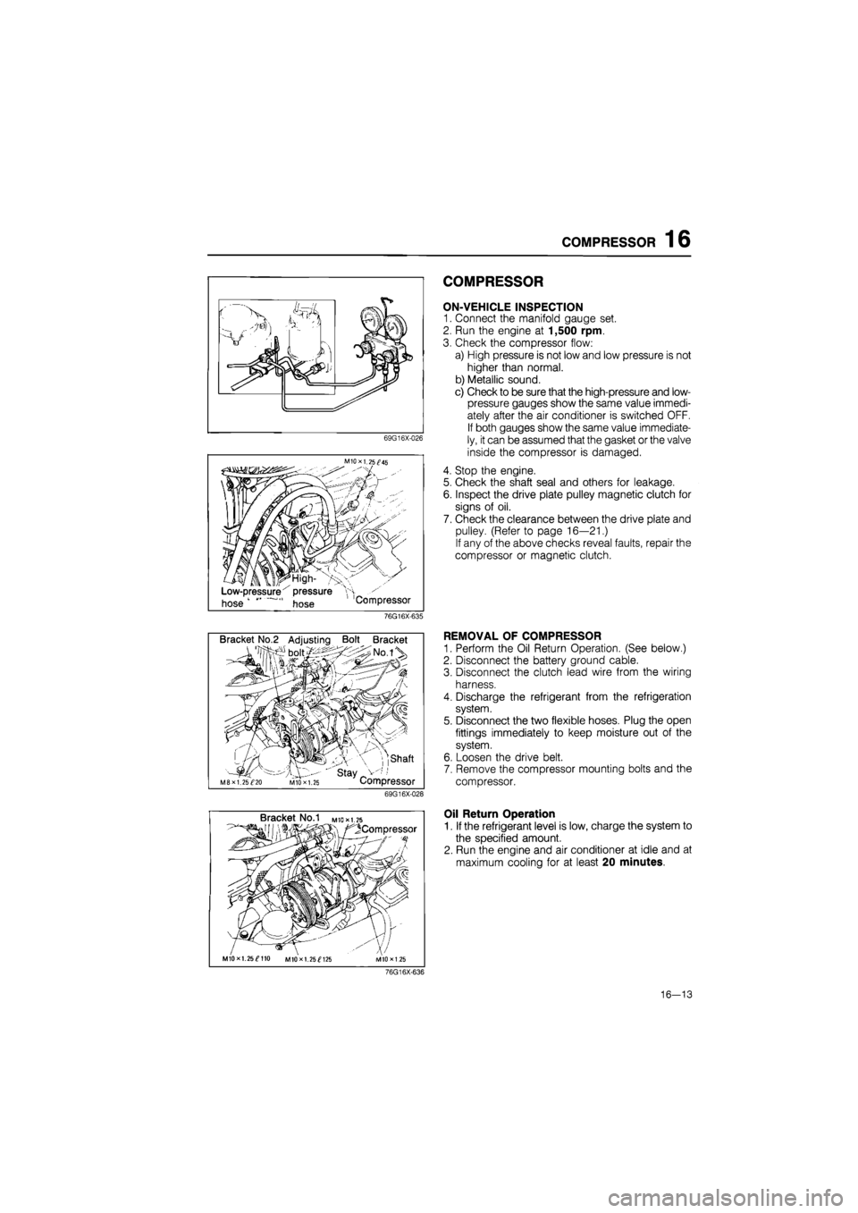
ON-VEHICLE INSPECTION
1. Connect the manifold gauge set.
2. Run the engine at 1,500 rpm.
3. Check the compressor flow:
a) High pressure is not low and low pressure is not
higher than normal.
b) Metallic sound.
c) Check to be sure that the high-pressure and low-
pressure gauges show the same value immedi-
ately after the air conditioner is switched OFF.
If both gauges show the same value immediate-
ly, it can be assumed that the gasket or the valve
inside the compressor is damaged.
4. Stop the engine.
5. Check the shaft seal and others for leakage.
6. Inspect the drive plate pulley magnetic clutch for
signs of oil.
7. Check the clearance between the drive plate and
pulley. (Refer to page 16—21.)
If any of the above checks reveal faults, repair the
compressor or magnetic clutch.
76G16X-635
Bracket No.2 Adjusting Bolt Bracket
, ,shaft
' stay _ M8XI. 25^20 MIO X 1.25 Compressor
69G16X-028
REMOVAL OF COMPRESSOR
1. Perform the Oil Return Operation. (See below.)
2. Disconnect the battery ground cable.
3. Disconnect the clutch lead wire from the wiring
harness.
4. Discharge the refrigerant from the refrigeration
system.
5. Disconnect the two flexible hoses. Plug the open
fittings immediately to keep moisture out of the
system.
6. Loosen the drive belt.
7. Remove the compressor mounting bolts and the
compressor.
Bracket No.1 M
to* 1.25
^Compressor
MIOxl. 25^110 MIOxl. 25^125
Oil Return Operation
1. If the refrigerant level is low, charge the system to
the specified amount.
2. Run the engine and air conditioner at idle and at
maximum cooling for at least 20 minutes.
76G16X-636
16—13
Page 1832 of 1865

30 TECHNICAL DATA
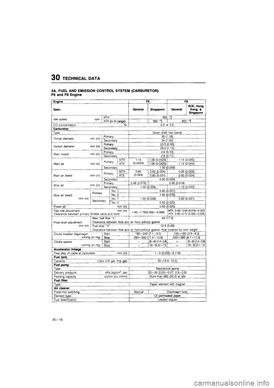
4A. FUEL AND EMISSION CONTROL SYSTEM (CARBURETOR)
F6 and F8 Engine
Engine F6 F8
Spec. General Singapore General
ECE, Hong
Kong, &
Singapore
Idle speed rpm MTX 800
+ 50
0 Idle speed rpm ATX (in
N
range)
—
950 +58 900
+ 50
0
CO concentration °/o 2.0
± 0.5
Carburetor
Type Down draft two barrel
Throat diameter mm (in) Primary 30 (1.18) Throat diameter mm (in) Secondary 34 (1.34)
Venturi diameter mm (in) Primary 23.5 (0.93) Venturi diameter mm (in) Secondary 29.0 (1.14)
Main nozzle mm (in) Primary 2.6 (0.10) Main nozzle mm (in) Secondary 2.8 (0.11)
Primary MTX 1.10 1.09 (0.0429) 1.14 (0.045)
Main
jet
mm (in) Primary ATX (0.0433) 1.08 (0.0425) 1.12 (0.044)
Secondary 1.50 (0.059)
Primary MTX 0.60 0.60 (0.024) 0.55 (0.022)
Main
air
bleed mm (in) Primary ATX (0.024) 0.80 (0.031) 0.60 (0.024)
Secondary 0.50 (0.020)
Slow
jet
mm (in) Primary 0.48 (0.019) 0.46 (0.018) Slow
jet
mm (in) Secondary 1.00 (0.039) 1.10 (0.043)
Primary No.
1
0.80 (0.031)
Slow
air
bleed Primary No.
2
1.90 (0.075)
mm (in) Secondary No.
1
1.00 (0.039) 0.80 (0.031) Secondary No.
2
0.50 (0.020)
Power
jet
mm (in) 0.50 (0.020)
Fast idle adjustment
mm (in)
Clearance between primary throttle valve and bore 1.40-1.76(0.055-0.069) MTX: 0.48-0.64 (0.019-0 025) ATX: 0.56-0.72 (0.022-0.028)
Max. fuel flow
"L"
44 (17.3)
Float level adjustment Clearance between float and
air
horn without gasket
mm (in) Fuel stop
"H •
12.5 (0.49)
Clearance between float and
air
horn/without gasket; float lowered
by
own weight
Choke breaker diaphragm Start 180-240 (7.1-9.5) 100—160 (3.9-6.3)
mmHg
(in Hg)
Stop 290—350 (11.4-13.8) 220-280 (8.7-11.0)
Choke opener Start
—
35-65 (1.4-2.6)
—
35-65 (1.4-2.6)
mmHg
(in Hg)
Stop
—
130-190 (5.1-7.5)
—
130-190
(5,1-7.5)
Accelerator linkage
Free plav
of
cable
at
carburetor mm (in) 1-3 (0.039—0.118)
Fuel tank
Capacity Liters (US gal, Imp gal) 60 (15.9, 13.2)
Fuel pump
Type Mechanical pump
Delivery pressure kPa (kg/cm2,
psi)
20-26 (0.20-0.27, 2.8-3.8)
Feedina capacity cc/min (cu in/min) More than 860 (52.5)
at
idle
Fuel filter
Type Paper element with magnet
Air cleaner
Fresh-Hot switching Manual Diaphragm type
Element
tvDe
Oil permeated paper
Fuel specification Leaded regular
30-18
Page 1833 of 1865

TECHNICAL DATA 30
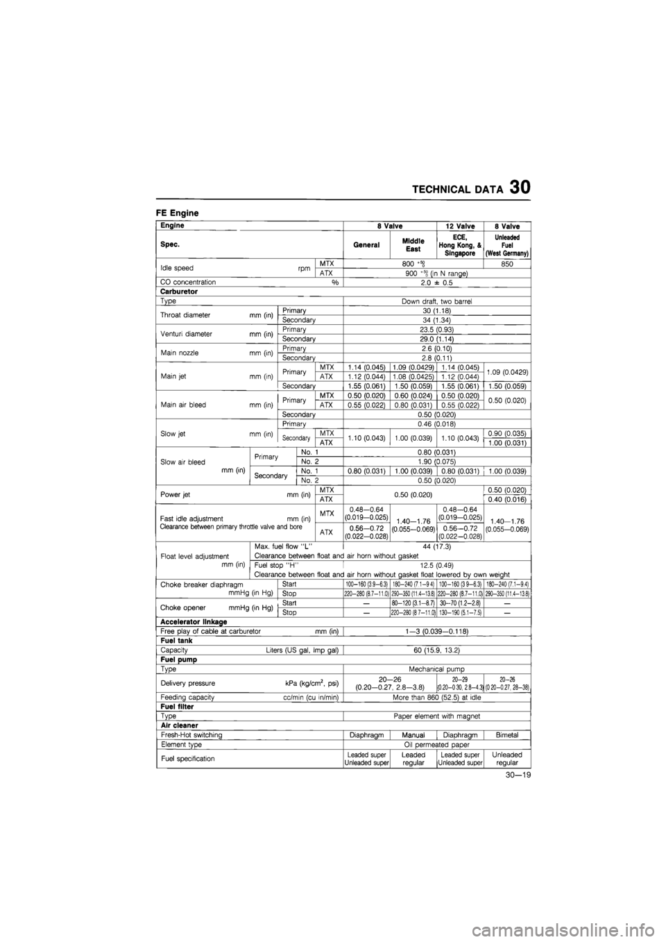
FE Engine
Engine 8 Valve 12 Valve 8 Valve
Spec. General Middle
East
ECE,
Hong Kong, &
Singapore
Unleaded
Fuel
(West Germany)
Idle speed rpm MTX 800
+5§
850 Idle speed rpm ATX 900 +5S
(ir
N range)
CO concentration
%
2.0
± 0,5
Carburetor
Type Down draft, two barrel
Throat diameter mm (in) Primary 30 (1.18) Throat diameter mm (in) Secondary 34 (1.34)
Venturi diameter mm (in) Primary 23.5 (0.93) Venturi diameter mm (in) Secondary 29.0 (1.14)
Main nozzle mm (in) Primary 2.6 (0.10) Main nozzle mm (in) Secondary 2.8 (0.11)
Primary MTX 1.14 (0.045) 1.09 (0.0429) 1.14 (0.045) 1.09 (0.0429) Main
jet
mm (in) Primary ATX 1.12 (0.044) 1.08 (0.0425) 1.12 (0.044) 1.09 (0.0429)
Secondary 1.55 (0.061) 1.50 (0.059) 1.55 (0.061) 1.50 (0.059)
Primary MTX 0.50 (0.020) 0.60 (0.024) 0.50 (0.020) 0.50 (0.020) Main
air
bleed mm (in) Primary ATX 0.55 (0.022) 0.80 (0.031) 0.55 (0.022) 0.50 (0.020)
Secondary 0.50 (0.020)
Primary 0.46 (0.018)
Slow jet mm (in) Secondary MTX 1.10 (0.043) 1.00 (0.039) 1.10 (0.043) 0.90 (0.035) Secondary ATX 1.10 (0.043) 1.00 (0.039) 1.10 (0.043) 1.00 (0.031)
Primary No.
1
0.80 (0.031)
Slow
air
bleed Primary No.
2
1.90 (0.075)
mm (in) Secondary No.
1
0.80 (0.031) 1.00 (0.039) 0.80 (0.031) 1.00 (0.039) Secondary No.
2
0.50 (0.020)
Power jet mm (in) MTX 0.50 (0.020) 0.50 (0.020) Power jet mm (in) ATX 0.50 (0.020) 0.40 (0.016)
Fast idle adjustment mm (in) MTX 0.48-0.64 (0.019-0.025) 1 40—1
76
0.48-0.64 (0.019-0.025) 1
40
1
76
Clearance between primary throttle valve and bore ATX 0.56-0.72
(0.022-0.028) (0.055-0.069) 0.56-0.72 (0.022-0.028) (0.055-0.069)
Max. fuel flow
"L"
44 (17.3)
Float level adjustment Clearance between float and
air
horn without aasket
mm (in) Fuel stop
"H •
12.5 (0.49)
Clearance between float and
air
horn without aasket float lowered
bv
own weiaht
Choke breaker diaphragm Start
100-160 (3,9-6.3) 180-240 (7.1-94) 100-160 (39-6.3) 180-240 (7.1-9,4)
mmHg
(in Hg)
Stop
220-280 (8.7-11,0) 290-350 (11,4-13.8) 220-280 (8.7-11.0) 290-350 (11.4-13.8)
Choke opener mmHg (in
Hg)
Start
—
80-120 (3.1-8.7) 30-70 (1.2-2.8)
—
Choke opener mmHg (in
Hg)
Stop
—
220-280 (87-11.0) 130-190 (5.1-7.5)
—
Accelerator llnkaae
Free play
of
cable
at
carburetor mm (in) 1-3 (0.039-0.118)
Fuel tank
Capacity Liters (US gal, Imp gal) 60 (15.9, 13.2)
Fuel pump
TvDe
Mechanical pump
Delivery pressure kPa (kg/cm2,
psi)
20-26 (0.20-0.27, 2.8-3.8)
20-29 (0.20-030, 2.8-4.3) 20-26
(020-0.27, 28-38)
Feeding capacity cc/min (cu in/min) More than 860 (52.5)
at
idle
Fuel filter
TvDe
Paoer element with maanet
Air cleaner
Fresh-Hot switchina Diaohraam Manual Diaohraam Bimetal
Element tvoe Oil oermeated oaoer
Fuel specification Leaded super Unleaded super Leaded regular Leaded super Unleaded super Unleaded regular
30-19