Page 1502 of 1865
OUTLINE 13
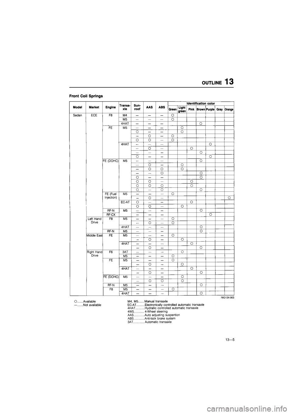
Front Coil Springs
Transa-
xle
Sun-
roof
Identification color
Model Market Engine Transa-
xle
Sun-
roof AAS ABS Green Light
green Pink Brown Purple Gray Orange
Sedan ECE F8 M4 — — — O
M5 — — — 0
4HAT — — — O
FE M5 — — — O
0 — — O
— o — o
o o — o
4HAT -— — o
— o — O
— — — o
o — — o
FE (DOHC) M5 — — — o
— o — 0
— o o o
— — o o
0 — — o
o o — o
0 0 o o
o — 0 o
FE (Fuel M5 — — — o
Injection) — 0 — O
EC-AT O — — o
o o — o
RF-N M5 — — — 0
RF-CX — — — o
Left Hand F8 M5 — — — o
Drive „ o — o
4HAT — — — o
RF-N M5 — — — o
Middle East FE M5 — — — o
-o — o
4HAT — — — o
— o — 0
Right Hand F6 3AT — — — 0
Drive M5 — — — o
FE M5 — — — 0
— o _ o
4HAT — — — o
— 0 — o
FE (DOHC) M5 — — — o
— o o 0
RF-N M5 — — — o
F8 M5 — — — 0
4HAT — — — o
76G13X003
O Available M4, M5.... ...Manual transaxle
— Not available EC-AT ....Electronically controlled automatic transaxle 4HAT ....Hydrallic controlled automatic transaxle
4WS ... 4-Wheel steering
AAS ....Auto adjusting suspention ABS ....Anti-lock brake system
3AT ... Automatic transaxle
13—5
Page 1583 of 1865
1 4 REAR COMBINATION LIGHTS
REAR COMBINATION LIGHTS
REMOVAL AND INSTALLATION
1. Disconnect the negative battery cable.
2. Remove in the sequence shown in the figure.
3. Install in the reverse order of removal.
76G14X-010
Hatchback
1. End trim
2. Nuts
3. Lens and body
4. Cover
5. Bulb: Turn signal light 21W
Brake and tail light 21W
Side marker light 5W
Sedan and Coupe/MX-6
1. End trim
2. Nuts
3. Lens and body
4. Cover
5. Bulb: Turn signal light 21W
Brake and tail light 21W
Side marker light 5W
14—32
Page 1687 of 1865
1 5 WARNING LIGHT AND SENDER
TROUBLESHOOTING
Note
Check the "Meter 10 or 15A" fuse in the fuse box before troubleshooting. If normal, refer
to the following troubleshooting chart.
Brake System Warning Light
76G15X-033
76G15X034
15-32
Page 1694 of 1865
WARNING AND SENDER 15
Coolant Level Warning Light
OK
Repair harness (Meter
to
coolant level sensor).
76G15X093
INSPECTION
Brake Fluid Level Sensor
1. Check for continuity of the sensor with an
ohmmeter.
Float level Continuity
Below
min
Yes
Above
min
No
2. If continuity is not as specified, replace the sensor.
86U15X-065
86U14X-066
Parking Brake Switch
1. Check for continuity between (R) terminal and a
body ground with an ohmmeter.
Lever Continuity
Pulled one notch Yes
Released No
2. If continuity is not as specified, adjust the switch
or replace the switch.
15—39
Page 1705 of 1865
1 5 STOP LIGHT
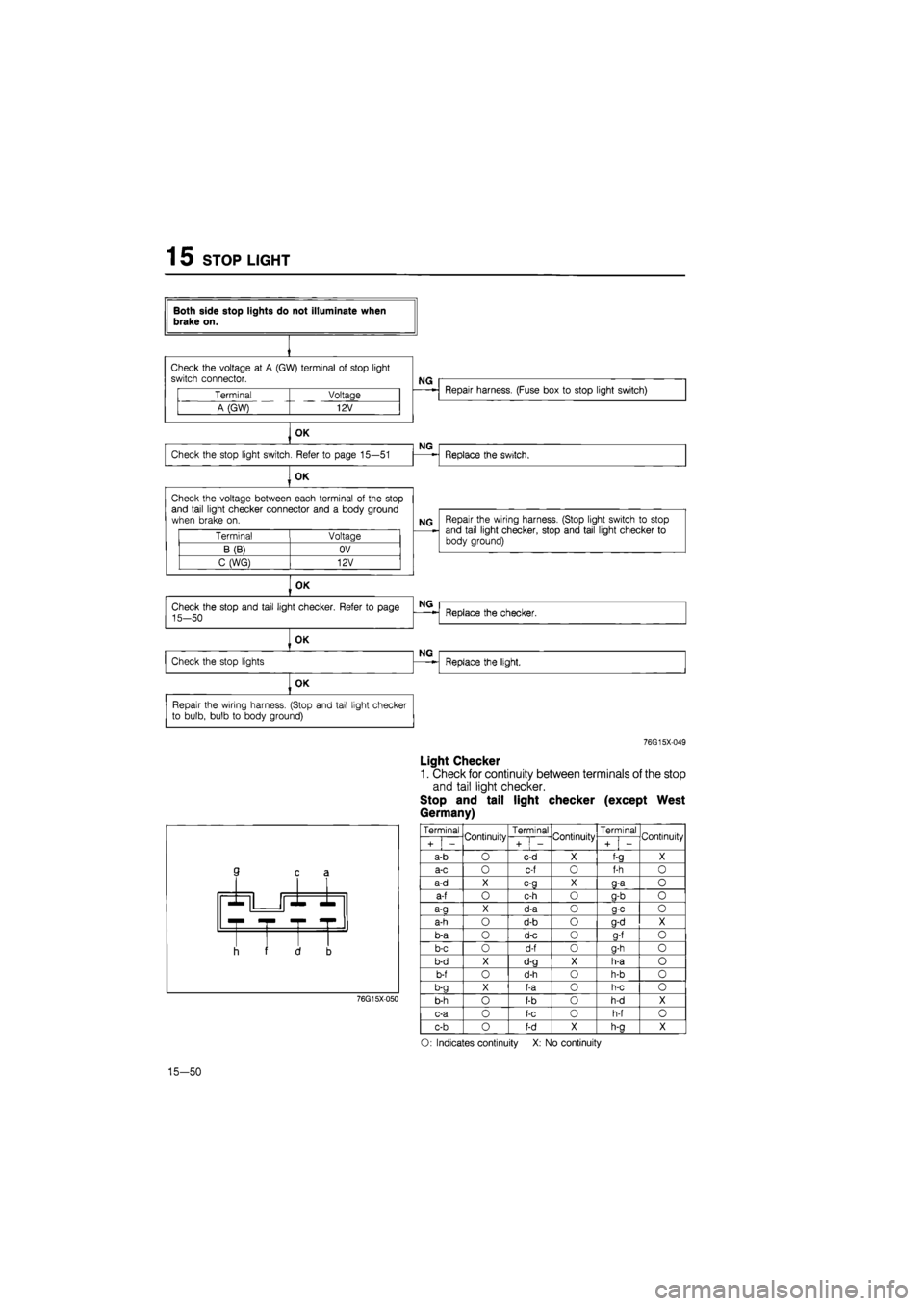
Both side stop lights do not illuminate when brake on.
Check the voltage
at A
(GW) terminal
of
stop light switch connector.
NG
Terminal Voltage
A (GW) 12V
Repair harness. (Fuse box
to
stop light switch)
OK
Check the stop light switch. Refer
to
page 15—51
NG
Replace the switch.
OK
Check the voltage between each terminal
of
the stop and tail light checker connector and
a
body ground when brake
on.
Terminal Voltage
B(B) OV
C (WG) 12V
NG Repair the wiring harness. (Stop light switch
to
stop and tail light checker, stop and tail light checker
to
body ground)
OK
OK
Repair the wiring harness. (Stop and tail light checker to bulb, bulb
to
body ground)
76G15X-049
Light Checker
1. Check for continuity between terminals of the stop
and tail light checker.
Stop and tail light checker (except West
Germany)
3 c £
r -r •
I i f 1 3
76G15X050
Terminal Continuity Terminal Continuity Terminal Continuity
i + i -
Continuity
+
1
-
Continuity
i + i -
Continuity
a-b
O
c-d
X
f-a
X
a-c
O
c-f
o
f-h
0
a-d
X c-g X g-a o
a-f
o
c-h
o
g-b
o
a-a
X
d-a
o a-c o
a-h
o
d-b
o
g-d
X
b-a
o
d-c
0
a-f
o
b-c
o
d-f
o
g-h
o
b-d
X
d-g
X
h-a
o
b-f
o
d-h
o
h-b
o
b-g
X
f-a
0
h-c
o
b-h
o
f-b
o
h-d
X
c-a
0
f-c
o
h-f
o
c-b
o
f-d
X
h-a
X
O: Indicates continuity
X: No
continuity
15-50
Page 1739 of 1865
1 5 CRUISE CONTROL SYSTEM
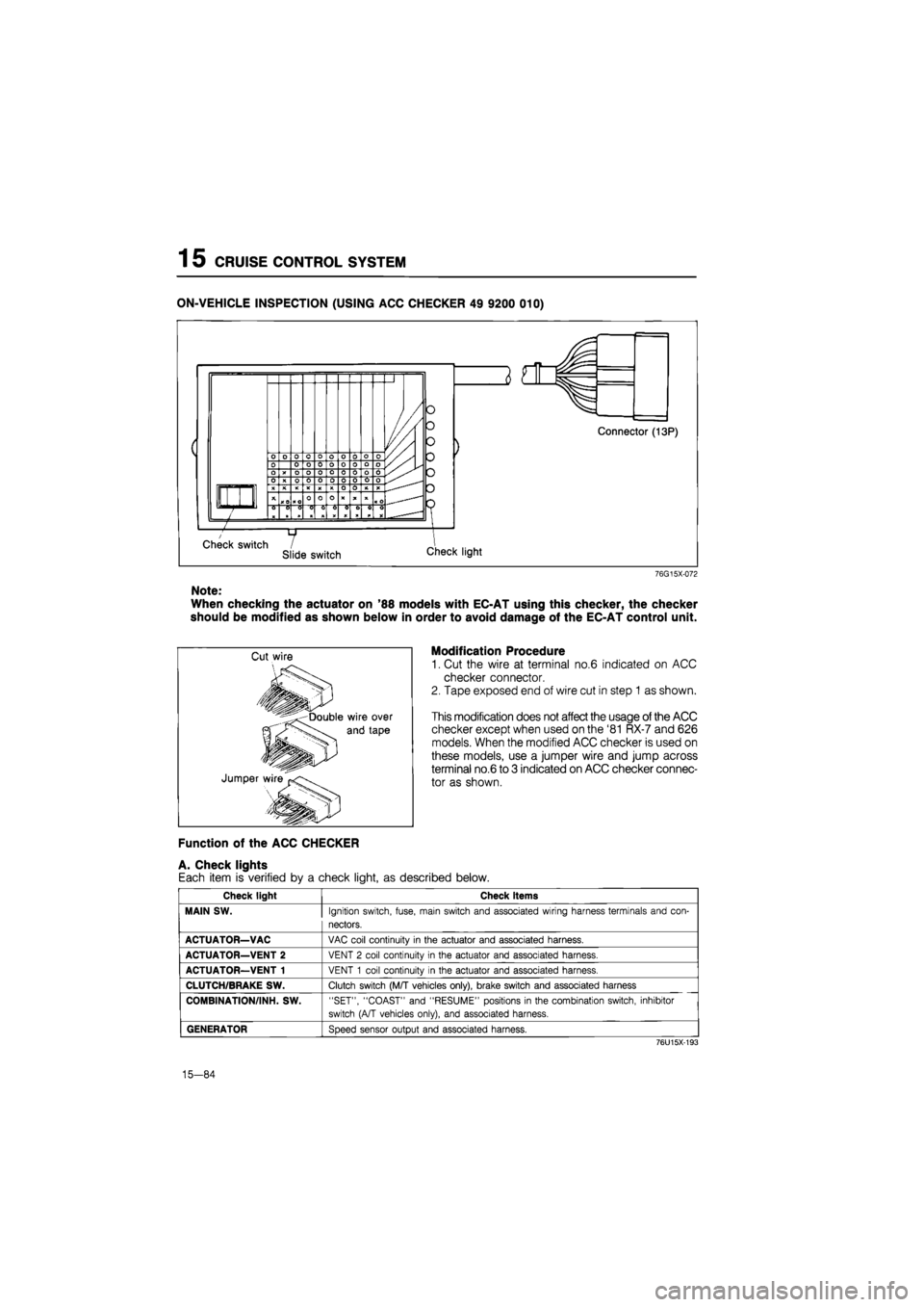
ON-VEHICLE INSPECTION (USING ACC CHECKER 49 9200 010)
76G15X-072
Note:
When checking the actuator on '88 models with EC-AT using this checker, the checker
should be modified as shown below in order to avoid damage of the EC-AT control unit.
Modification Procedure
1. Cut the wire at terminal no.6 indicated on ACC
checker connector.
2. Tape exposed end of wire cut in step 1 as shown.
This modification does not affect the usage of the ACC
checker except when used on the '81 RX-7 and 626
models. When the modified ACC checker is used on
these models, use a jumper wire and jump across
terminal no.6 to 3 indicated on ACC checker connec-
tor as shown.
Function of the ACC CHECKER
A. Check lights
Each item is verified by a check light, as described below.
Check light Check items
MAIN SW.
Ignition switch, fuse, main switch and associated wiring harness terminals and con-
nectors.
ACTUATOR—VAC
VAC coil continuity
in
the actuator and associated harness.
ACTUATOR—VENT 2
VENT
2
coil continuity
in
the actuator and associated harness.
ACTUATOR—VENT 1
VENT
1
coil continuity
in
the actuator and associated harness.
CLUTCH/BRAKE SW.
Clutch switch (M/T vehicles only), brake switch and associated harness
COMBINATION/INH. SW.
"SET", "COAST" and "RESUME" positions
in
the combination switch, inhibitor
switch (A/T vehicles only), and associated harness.
GENERATOR
Speed sensor output and associated harness.
76U15X-193
15-84
Page 1741 of 1865
1
5
CRUISE CONTROL SYSTEM
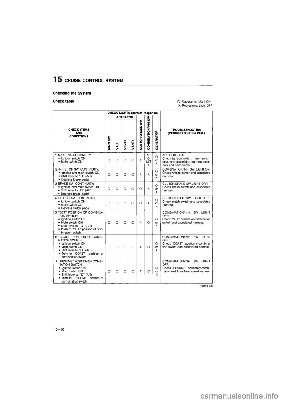
Checking
the
System
Check table O:
Represents: Light ON
X: Represents: Light OFF
CHECK LIGHTS (correct response)
ACTUATOR 5
CHECK ITEMS AND CONDITIONS
MAIN
SW
VAC
i
VENT2 VANT1
i
'
CLUTCH/BRAKE
SW
CONBINATION/INH
S
'
GENERATOR
TROUBLESHOOTING (INCORRECT RESPONSE)
1. MAIN SW. CONTINUITY:
• Ignition switch
ON
• Main switch
ON O O O o
X
A/T
O
M/T X
O
or X
ALL LIGHTS OFF: Check ignition switch, main switch, fuse, and associated harness termi-nals and connectors
2. INHIBITOR SW. CONTINUITY:
• Ignition and main switch ON. • Shift lever
to "D"
(A/T)
• Depress brake pedal
o o o o
X X
0
or X
COMBINATION/INH. SW. LIGHT ON:
Check inhibitor switch and associated
harness.
3. BRAKE SW. CONTINUITY: • Ignition and main switch
ON
• Shift lever
to
"D"
(A/T)
• Depress brake pedal
o o o o 0
X
o
or X
CLUTCH/BRAKE SW.LIGHT OFF:
Check brake switch and associated
harness.
4. CLUTCH SW. CONTINUITY:
• Ignition switch
ON
• Main switch
ON
• Depress clutch pedal
o o o 0 o
X
O
or X
CLUTCH/BRAKE SW. LIGHT OFF: Check clutch switch and associated harness.
5. "SET" POSITION
OF
COMBINA-TION SWITCH:
• Ignition switch
ON
• Main switch
ON
• Shift lever
to "D"
(A/T) • Push
to
"SET" position
of
com-bination switch
o o o o
X
o
O
or X
COMBINATION/INH.
SW.
LIGHT OFF: Check "SET" position of combination switch and associated harness.
6. "COAST" POSITION
OF
COMBI-NATION SWITCH • Ignition switch
ON
• Main switch
ON
• Shift lever
to "D"
(A/T) • Turn
to
"COAST" position
of
combination switch
o o o o
X
o
O
or X
COMBINATION/INH.
SW.
LIGHT OFF: Check "COAST" position in combina-tion switch and associated harness.
7. "RESUME" POSITION OF COMBI-NATION SWITCH
• Ignition switch
ON
• Main switch
ON
• Shift lever
to "D"
(A/T)
• Turn
to
"RESUME" position
of
combination switch
o o o o
X
o O
or X
COMBINATION/INH.
SW.
LIGHT OFF: Check "RESUME" position of combi-nation switch and associated harness.
76U15X-198
15—86
Page 1742 of 1865
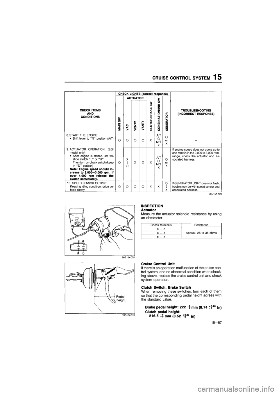
CRUISE CONTROL SYSTEM 1 5
CHECK LIGHTS (correct response)
ACTUATOR £
5 (O
W X
CHECK ITEMS AND CONDITIONS £ <0 z
VAC
CM I-1-z
Ul * < IE ffl X o V-
z o F < z ta
DC O 1-< DC Ui
TROUBLESHOOTING
(INCORRECT RESPONSE)
< S VAC UJ > < > -1 o o o UJ O
8. START THE ENGINE
• Shift lever to "N" position (A/T) O O O o X
A/T
O M/T X
O or X —
9. ACTUATOR OPERATION: (EGI model only) • After engine is started, set the slide switch "L" or "H". Then turn on check switch (keep in "D" position) Note: Engine speed should in-crease to 2,000—3,000 rpm. If over 4,000 rpm release the switch immediately.
o
X
1
o
X X X
A/T O M/T X
O or X
If engine speed does not come up to and remain
in
the
2,000
to
3,000
rpm. range, check the actuator and as-sociated harness.
10. SPEED SENSOR OUTPUT
Keeping idling condition, drive ve-
hicle slowly. o o 0 o X X 0 1 X
If GENERATOR LIGHT does not flash, trouble may be with speed sensor and associated harness.
76U15X-199
INSPECTION
Actuator
Measure the actuator solenoid resistance by using
an ohmmeter.
Check terminals Resistance
c-d
Approx. 25 to 35 ohms c — a Approx. 25 to 35 ohms
c — b
Approx. 25 to 35 ohms
76G15X-075
Cruise Control Unit
If there is an operation malfunction of the cruise con-
trol system, and no abnormal condition when check-
ing above, replace the cruise control unit and check
system operation.
Clutch Switch, Brake Switch
When removing these switches, turn each of them
so that the corresponding pedal height agrees with
the standard value.
76G15X-076
Brake pedal height: 222 ±1 mm (8.74 1820
Clutch pedal height:
216.5 ±8 mm (8.52 ±820 In)
in)
15-87