Page 1483 of 1865
ANTI-LOCK BRAKE SYSTEM (ABS) 1 1
Installation of Front Sensor Rotor
Install in the reverse order of removal, referring
Torque specifications
Removal note
Sensor rotor
Tap the sensor rotor off the drive shaft with a chisel.
to installation note for the specially marked parts.
Installation note
Sensor rotor
Press the sensor rotor onto the driveshaft with the
SST.
Caution
Install the sensor rotor with chamfered edge
toward the driveshaft.
11—91
Page 1488 of 1865
1 1 ANTI-LOCK BRAKE SYSTEM (ABS)
t
2. Bleed air from the system.
3. Depress the brake pedal, and compare the fluid
pressure of the front brake with that of the rear
brake.
Fluid pressure kPa (kg/cm2, psi)
Front brake side Rear brake side
A 2,943 (30,427)
A'
2,747-3,139
(28-32, 398-455)
A B
B 6,867 (70,995)
B'
3,924-4,316 (40-44, 569-626)
Front brake pressure kPa (kg/cm2, psi) 4. If the measurement is not within specification re-
place the hydraulic unit assembly. 86U11X-194
REMOVAL
Caution
a) Brake fluid will damage painted surfaces. If it does get on the painted surfaces, wipe
it off immediately.
b) Oo not tip the hydraulic unit to prevent the brake fluid in the reservoir from draining.
1. Remove the nuts mounting the fuel filter and ignitor to the bracket and move them toward the engine.
2. Remove the air cleaner assembly.
3. Remove the master cylinder. (Refer to page 11—14.)
4. Remove the hydraulic unit in the sequence shown in the figure.
76G11X-062
11—96
Page 1511 of 1865
1 3 FRONT SHOCK ABSORBER AND SPRING
AAS actuator
1. Disconnect the AAS actuator connector.
2. Remove the AAS actuator.
86U13X-011
Shock absorber clinch bolts and nuts
1. Remove the shock absorber clinch bolts and nuts.
2. Remove the shock absorber upper mounting nuts.
76G13X-013
Installation Note
Mounting block
Install the mounting block to the suspension tower
with the white mark facing the front-inside direction.
Tightening torque: 46—63 N-m
(4.7—6.4 m-kg, 34—46 ft-lb)
86U13X-013
Shock absorber clinch bolts and nuts
Install the clinch bolts and nuts.
Tightening torque: 93—117
N
m
(9.5—11.9 m-kg, 69—86 ft-lb)
86U13X-014
13—14
Page 1547 of 1865

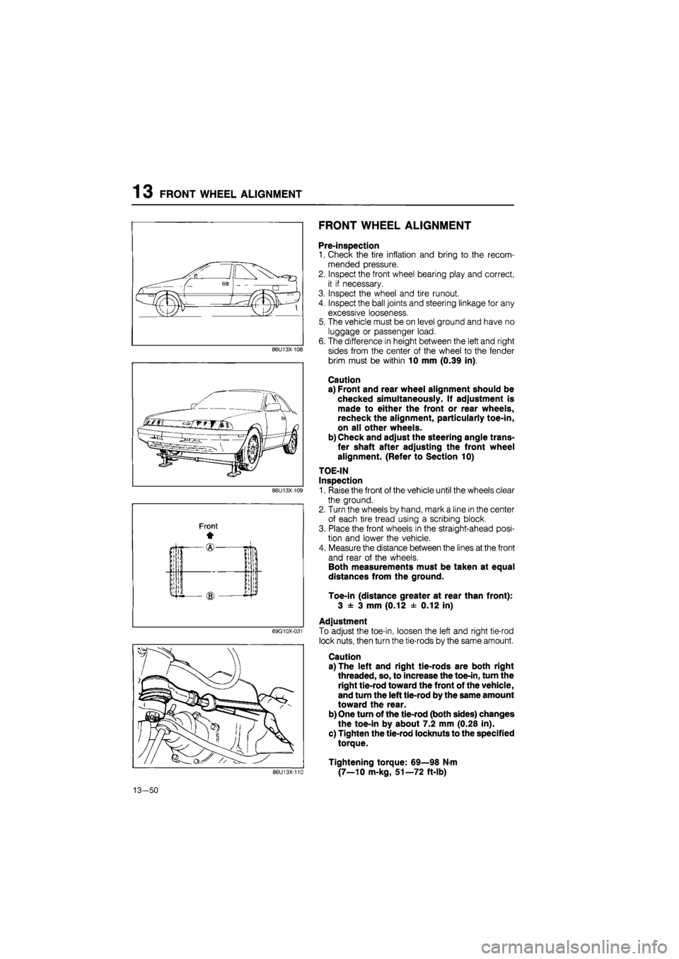
1 3 FRONT WHEEL ALIGNMENT
FRONT WHEEL ALIGNMENT
86U13X-108
69G10X-031
Pre-inspection
1. Check the tire inflation and bring to the recom-
mended pressure.
2. Inspect the front wheel bearing play and correct,
it if necessary.
3. Inspect the wheel and tire runout.
4. Inspect the ball joints and steering linkage for any
excessive looseness.
5. The vehicle must be on level ground and have no
luggage or passenger load.
6. The difference in height between the left and right
sides from the center of the wheel to the fender
brim must be within 10 mm (0.39 in).
Caution
a) Front and rear wheel alignment should be
checked simultaneously. If adjustment is
made to either the front or rear wheels,
recheck the alignment, particularly toe-in,
on all other wheels.
b) Check and adjust the steering angle trans-
fer shaft after adjusting the front wheel
alignment. (Refer to Section 10)
TOE-IN
Inspection
1. Raise the front of the vehicle until the wheels clear
the ground.
2. Turn the wheels by hand, mark a line in the center
of each tire tread using a scribing block.
3. Place the front wheels in the straight-ahead posi-
tion and lower the vehicle.
4. Measure the distance between the lines at the front
and rear of the wheels.
Both measurements must be taken at equal
distances from the ground.
Toe-in (distance greater at rear than front):
3 ± 3 mm (0.12 ± 0.12 in)
Adjustment
To adjust the toe-in, loosen the left and right tie-rod
lock nuts, then turn the tie-rods by the same amount.
Caution
a) The left and right tie-rods are both right
threaded, so, to increase the toe-in, turn the
right tie-rod toward the front of the vehicle,
and turn the left tie-rod by the same amount
toward the rear.
b) One turn of the tie-rod (both sides) changes
the toe-in by about 7.2 mm (0.28 in).
c) Tighten the tie-rod locknuts to the specified
torque.
Tightening torque: 69—98 N-m
(7—10 m-kg, 51—72 ft-lb) 86U13X-110
13-50
Page 1550 of 1865
REAR WHEEL ALIGNMENT 13
86U13X-119
Adjustment (4WS)
To adjust the toe-in, loosen the left and right tie-rod
locknuts, and turn the tie-rods by the same amount.
Caution
a) The left and right tie-rods are both right
threaded, so, to increase the toe-in, turn the
right tie-rod toward the front of the vehicle,
and turn the left tie-rod by the same amount
toward the rear.
b) One turn of the tie-rod (both sides) changes
the toe-in by about 7.8 mm (0.31 in).
c) Adjust the toe-in after adjusting the steer-
ing angle.
Tighten the tie-rod locknuts to the specified torque.
Tightening torque: 69—98 N-m
(7—10 m-kg, 51—72 ft-lb)
86U13X-120
CAMBER
Preparation
1. Remove the center caps from the wheels.
2. Uncrimp the locknut and remove it.
86U13X-121
Inspection
1. Install the SST to the driveshaft.
86U13X-122
13—53
Page 1601 of 1865

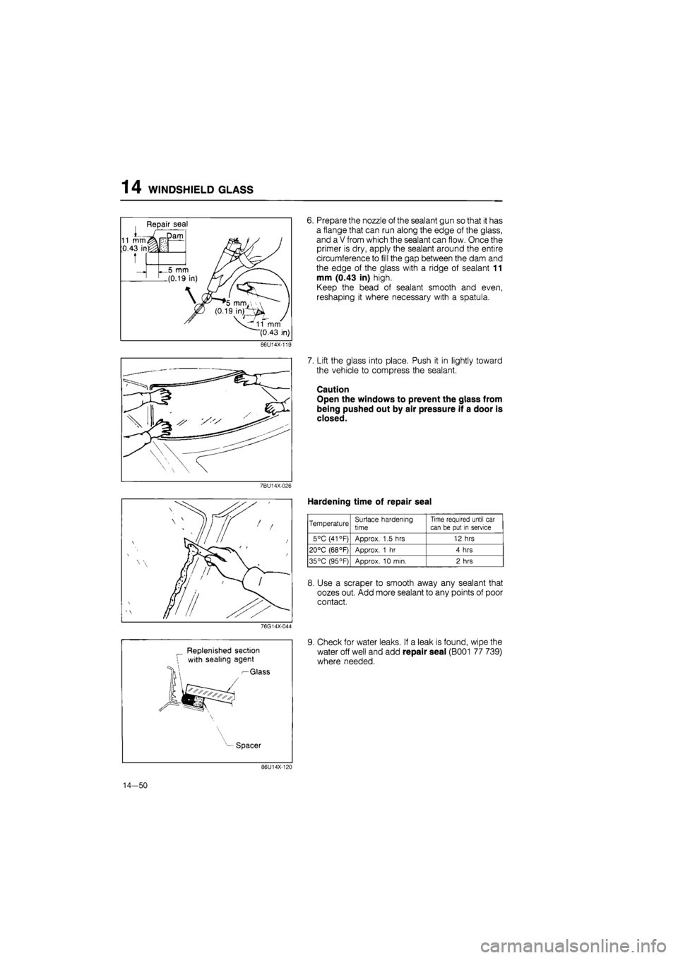
14 WINDSHIELD GLASS
Repair seal
Dam
_5 mm
.(0.19
11 mm
(0.43 in)
6. Prepare the nozzle of the sealant gun so that it has
a flange that can run along the edge of the glass,
and a V from which the sealant can flow. Once the
primer is dry, apply the sealant around the entire
circumference to fill the gap between the dam and
the edge of the glass with a ridge of sealant 11
mm (0.43 in) high.
Keep the bead of sealant smooth and even,
reshaping it where necessary with a spatula.
86U14X-11E
7BU14X-026
76G14X-044
Replenished section
with sealing agent
— Glass
7. Lift the glass into place. Push it in lightly toward
the vehicle to compress the sealant.
Caution
Open the windows to prevent the glass from
being pushed out by air pressure if a door is
closed.
Hardening time of repair seal
Temperature Surface hardening
time
Time required until car
can be put in service
5°C (41 °F) Approx. 1.5 hrs 12 hrs
20°C (68°F) Approx. 1 hr 4 hrs
35°C (95°F) Approx. 10 min. 2 hrs
8. Use a scraper to smooth away any sealant that
oozes out. Add more sealant to any points of poor
contact.
9. Check for water leaks. If a leak is found, wipe the
water off well and add repair seal (B001 77 739)
where needed.
Spacer
86U14X-120
14-50
Page 1634 of 1865
SLIDING SUNROOF 14
76U14X-047
Sun shade ^^Sun shade^,stopper
\ )j
/L.
^/''^//l J ' //r- OOf^/l
76U14X-048
76U14X-049
Connector
7. Turn the handle and move the sun shade 5—10
mm (0.19—0.39 in) to the rear.
8. Use a flat-tip screwdriver to lift the sun shade stop-
per at the rear of the cable holder, then release
the stopper and move the sun shade toward the
front.
9. Turn the handle to fully open the lower panel.
(Leave the sun shade fully closed.)
10. Open the sun shade half way and remove the set
plate cap. Pull out the sun shade from the notch
of the set plate.
11. Use a flat-tip screwdriver to pry up the connector
at the rear of the deflector link, being careful not
to scratch it, and remove the deflector link.
12. Remove the screws and remove the deflector.
Note
Because force is applied to the deflector by
the spring in the direction of opening, hold so
that the deflector doesn't contact the roof
panel, then pull out the deflector link.
76U14X-050
14—83
Page 1637 of 1865
1 4 SLIDING SUNROOF
3. After moving the guide bracket assembly slightly
toward the rear, tighten the screw, taking care
regarding the direction the set plate faces.
76U14X-059
Ipi
" (E) ling
Notch jilting Cam
—+ * ) siii
Align the projection of the tilting cam and the slit
in the set plate.
76U14X-060
5. Check that the limit switches (LS1 and LS2) of the
motor are as shown in the figure at the OFF po-
sition.
Note
a) Be careful of the cam position.
b) Use the handle to position it correctly.
76U14X-061
6. Install the motor assembly.
Note
There are 2 types of screws, long and short.
Be sure to use the correct ones.
7. Connect the wiring of the motor assembly and the
motor switch.
76U14X-062
14-86