Page 1317 of 1865
STEERING GEAR AND LINKAGE 1 0
86U10X-052
REMOVAL
Note
The power steering fluid will leak out when the
return hose or the pressure hose is discon-
nected. Prepare a suitable container for it to
drain into.
1. Disconnect the negative battery cable.
2. Disconnect the pressure switch connector.
3. Raise the vehicle on a lift or safety stands, and re-
move the front wheels.
4. Disconnect the power steering hose and pipe.
5. Disconnect the tie-rod ends from the knuckles with
the SST.
6. Remove the steering shaft universal joint.
86U10X-053
7. Remove the mud flap.
8. Remove the mounting bolts and the steering gear.
86U10X-054
10—29
Page 1325 of 1865
4-WHEEL STEERING GEAR AND LINKAGE 1 0
REMOVAL AND INSTALLATION
1. Jack up the vehicle and support it with safety stands.
2. Remove in the sequence shown in the figure, referring to the removal note for specially marked parts.
3. Install in the reverse order of removal, referring to installation note for specially marked parts.
4. Tighten all nuts and bolts to the specified torque, referring to page 10—39.
Note
The power steering fluid will leak out when the return hose or the pressure hose is discon-
nected. Prepare a suitable container for it to drain into.
Front Steering Gear
76G10X-034
9. Engine mount
10. Bolts and nut
11. Bolt
12. Bolt and mounting
13. Bolts and mounting
14. Stabilizer
15. Bolt
16. Front steering gear assembly
1. Pipes
2. Bolt
3. Exhaust pipe
4. Under cover
5. Shaft (Refer to next page)
6. Nuts retainer and bushing
7. Bolt, retainer and bushing
8. Nuts
10—37
Page 1371 of 1865
OIL PUMP 1 0
OIL PUMP
REMOVAL AND INSTALLATION
1. Jack up the front of the vehicle, and support it with safety stands.
2. Remove in the order shown in the figure, referring to the removal note for specially marked parts.
3. Install in the reverse order of removal.
4. Tighten all nuts and bolts to the specified torque, referring to the figure.
Note
a) The power steering fluid will leak out when the return hose or the pressure hose is dis-
connected. Prepare a suitable container for it to drain into.
b) After installation, inspect the deflection of the oil pump belt and bleed the air from the
system, then check for fluid leakage. 2WS (Gasoline engine)
76G10X-041
4. Bracket
5. Oil pump
6. Oil pump pulley
1. Belt
2. Nut
3. Pipes
10—83
Page 1421 of 1865
POWER BRAKE UNIT 1 1
76G11X-034
INSPECTION OF CHECK VALVE
Note (MTX)
The check valve is pressed into the vacuum
hose. There is an arrow on the hose surface
to indicate direction of installation.
Inspection
1. Disconnect the vacuum hose from the engine.
2. Apply suction and pressure to the hose from the
engine side. Check that air flows only toward the
engine.
If the air passes in both directions or not at all, re-
place the check valve (along with the hose).
REMOVAL
Remove in the sequence shown in the figure, referring to removal note for specially marked parts.
1. Fluid level sensor connector
2. Vacuum switch coupler
(RF, RF-CX)
3. Brake pipe
4. Master cylinder
5. Clutch pipe holder
6. Vacuum hose and check
valve
7. Clevis pin
8. Steering shaft
76G11X-069
9. Power brake unit
10. Gasket
11. Locknut
12. Operating lever
11-29
Page 1850 of 1865

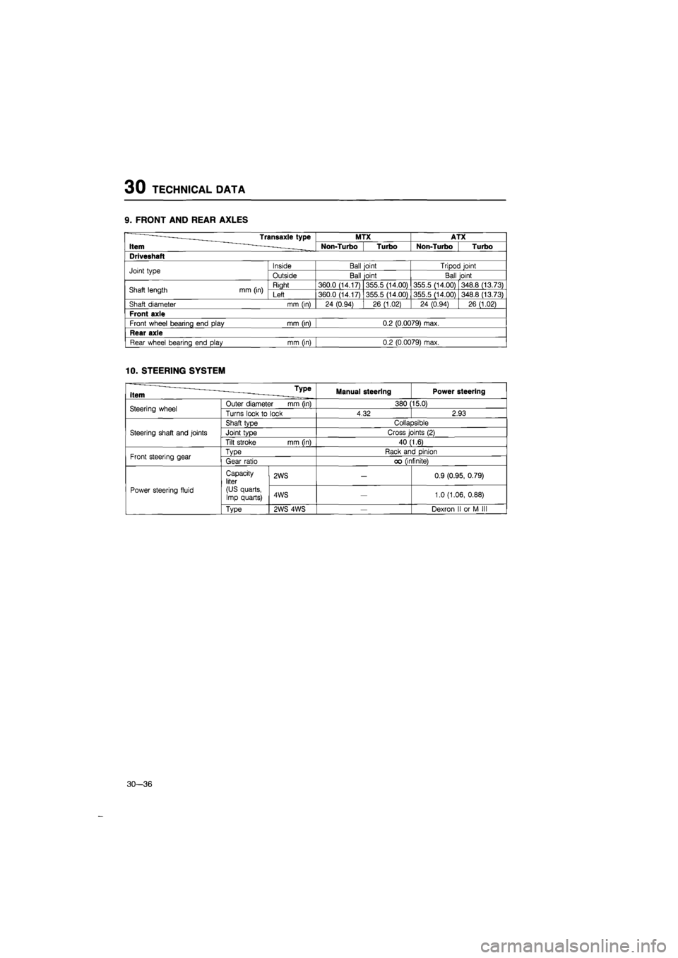
30 TECHNICAL DATA
9. FRONT AND REAR AXLES
Transaxle type MTX ATX
Item Non-Turbo Turbo Non-Turbo Turbo
Driveshaft
Joint type Inside Ball joint Tripod joint Joint type Outside Ball joint Ball joint
Shaft length mm (in) Right 360.0 (14.17) 355.5 (14.00) 355.5 (14.00) 348.8 (13.73) Shaft length mm (in) Left 360.0 (14.17) 355.5 (14.00) 355.5 (14.00) 348.8 (13.73)
Shaft diameter mm (in) 24 (0.94) 26 (1.02) 24 (0.94) 26 (1.02)
Front axle
Front wheel bearing end play mm (in) 0.2 (0.0079) max.
Rear axle
Rear wheel bearing end play mm (in) 0.2 (0.0079) max.
10. STEERING SYSTEM
u _ Type Item ——- - -. Manual steering Power steering
Steering wheel Outer diameter mm (in) 380 15.0) Steering wheel Turns lock
to
lock 4.32 2.93
Steering shaft and joints
Shaft type Collapsible
Steering shaft and joints Joint type Cross joints
(2)
Steering shaft and joints
Tilt stroke mm (in) 40 (1.6)
Front steering gear Type Rack and pinion Front steering gear Gear ratio
oo
(infinite)
Power steering fluid
Capacity liter
(US quarts, Imp quarts)
2WS
—
0.9 (0.95, 0.79)
Power steering fluid
Capacity liter
(US quarts, Imp quarts) 4WS
—
1.0 (1.06, 0.88) Power steering fluid
Type 2WS 4WS
—
Dexron
II or M III
30—36
Page:
< prev 1-8 9-16 17-24