Page 41 of 1865
TUNE-UP PROCEDURE 1A
High-Tension Lead
Check the following points. Clean or replace if
necessary.
1. Damaged lead
2. Carbon deposits
86U01X-014
76G01A-012
49 0187 280
76G01A-013
Carburetor Float Level (Carburetor)
1. Run the engine at idle.
2. Check that the fuel level is at the center of the float
level indicator window.
If necessary, adjust the fuel float level. (Refer to Sec-
tion 4A.)
Hydraulic Lash Adjuster (12 valve)
Note
Tappet noise may occur if the engine is not
operated for an extended period of time. The
noise should stop after the engine has
reached normal operating temperature.
1. Check for tappet noise. If noise exsits, check the
following points.
(1) Engine oil condition and level
(2) Engine oil pressure (Refer to Section 2A)
2. If the noise does not stop, check for movement of
each HLA by pushing down each rocker arm by
hand while at TDC of compression stroke.
3. If the rocker arm moves down, replace the HLA.
(Refer to page 1A—75.)
76G01A-014
1
A—9
Page 45 of 1865

ON-VEHICLE INSPECTION 1 A
ON-VEHICLE INSPECTION
If the engine exhibits low power, poor fuel economy,
or poor idle, check the following points.
1. Ignition system (Refer to Section 5)
2. Compression
3. Fuel system (Refer to Section 4)
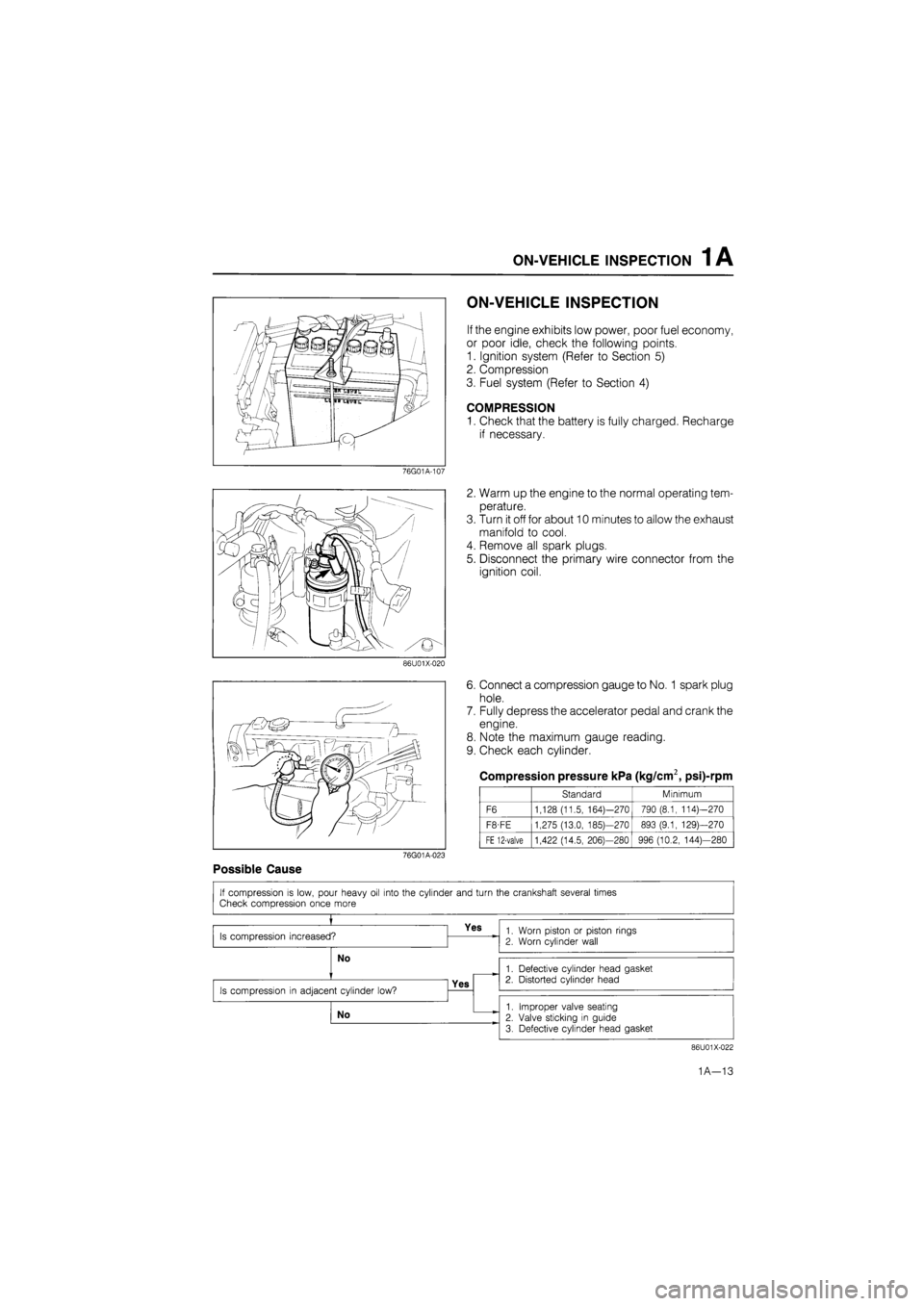
COMPRESSION
1. Check that the battery is fully charged. Recharge
if necessary.
76G01A-107
2. Warm up the engine to the normal operating tem-
perature.
3. Turn it off for about 10 minutes to allow the exhaust
manifold to cool.
4. Remove all spark plugs.
5. Disconnect the primary wire connector from the
ignition coil.
86U01X-020
6. Connect a compression gauge to No.
1
spark plug
hole.
7. Fully depress the accelerator pedal and crank the
engine.
8. Note the maximum gauge reading.
9. Check each cylinder.
Compression pressure kPa (kg/cm2, psi)-rpm
Standard Minimum
F6 1,128 (11.5, 164)—270 790 (8.1, 114)—270
F8-FE 1,275 (13.0, 185)—270 893 (9.1, 129)—270
FE 12-valve 1,422 (14.5, 206)—280 996 (10.2, 144)—280
76G01A-023
Possible Cause
86U01X-022
1A—13
Page 47 of 1865
1 A ON-VEHICLE MAINTENANCE (TIMING BELT)
Removal note
Timing belt tensioner
1. Turn the crankshaft to align the mating mark of the
camshaft pulley with the front housing timing mark.
Note
For FE engine, align "2" mark.
For F8, F6 engine, align "3" mark.
2. Remove the tensioner.
76G01A-025
Timing belt
Mark the timing belt rotation for proper reinstallation
if it is reused.
Caution
Be careful not to allow oil, grease, or water
on the belt.
86U01X-024
Inspection
Inspect the following parts.
(Refer to page 1A—60, 61.)
1. Timing belt
2. Timing belt tensioner and spring
3. Timing belt idler pulley
4. Timing belt pulley
5. Camshaft pulley
76G01A-026
1A—15
Page 49 of 1865

ON-VEHICLE MAINTENANCE (TIMING BELT) 1 A
76G01A-027
76G01B-024
76G01A-028
/Jf
ry.
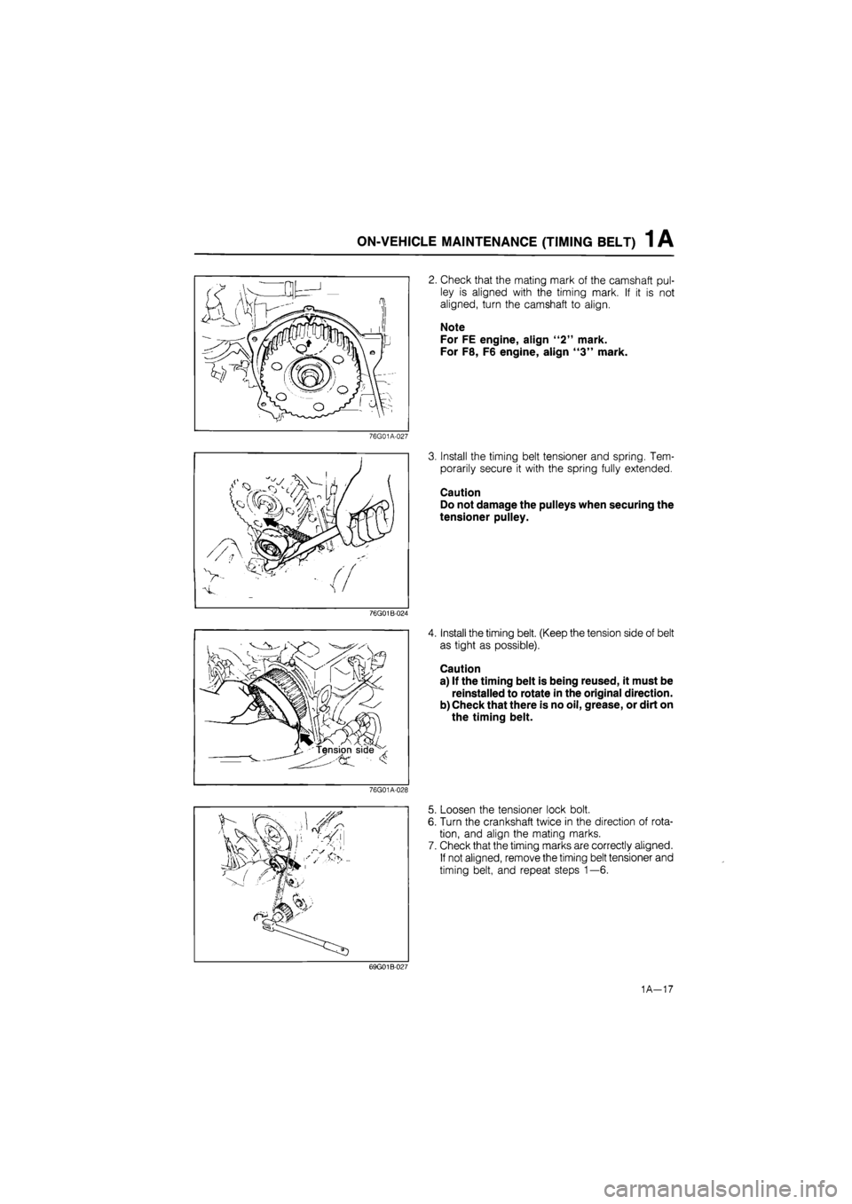
2. Check that the mating mark of the camshaft pul-
ley is aligned with the timing mark. If it is not
aligned, turn the camshaft to align.
Note
For FE engine, align "2" mark.
For F8, F6 engine, align "3" mark.
3. Install the timing belt tensioner and spring. Tem-
porarily secure it with the spring fully extended.
Caution
Do not damage the pulleys when securing the
tensioner pulley.
4. Install the timing belt. (Keep the tension side of belt
as tight as possible).
Caution
a) If the timing belt is being reused, it must be
reinstalled to rotate in the original direction.
b) Check that there is no oil, grease, or dirt on
the timing belt.
5. Loosen the tensioner lock bolt.
6. Turn the crankshaft twice in the direction of rota-
tion, and align the mating marks.
7. Check that the timing marks are correctly aligned.
If not aligned, remove the timing belt tensioner and
timing belt, and repeat steps 1—6.
69G01B-027
1A-17
Page 56 of 1865
1 A ON-VEHICLE MAINTENANCE (CYLINDER HEAD)
Installation note
Cylinder head
1. Thoroughly remove all dirt and oil from the top of
the cylinder block with a rag.
2. Place a new cylinder head gasket in position.
86U01X-035
®
(5)
CD
© (8)
3. Set the cylinder head in place.
4. Apply engine oil to the bolt threads and seat faces.
5. Tighten the cylinder head bolts in two or three steps
in the order shown in the figure.
Tightening torque:
80—86 N-m (8.2—8.8 m-kg, 59—64 ft-lb)
86U01X-036
Cylinder head cover
1. Apply silicon sealant to the shaded area shown in
the figure.
2. Install the cylinder head cover.
Tightening torque:
6—8
N
m (60—80 cm-kg, 52—69 in-lb)
86U01X-037
Timing belt
1. Align the mating mark of the camshaft pulley with
the front housing timing mark.
Note
For FE engine, align "2" mark.
For F8, F6 engine, align "3" mark.
2. Install the timing belt. (Refer to TIMING BELT of
ON-VEHICLE MAINTENANCE.)
76G01A-034
1A—24
Page 57 of 1865
ON-VEHICLE MAINTENANCE (CYLINDER HEAD) 1 A
76G01A-035
Engine harness connector
Install the engine harness connectors.
Distributor
1. Apply engine oil to the O-ring, and position it on
the distributor.
2. Apply engine oil to the blade or gear.
3. Align the mating marks as shown in the figure
...8-valve.
4. Install the distributor with the marks facing straight
up.
5. Loosely tighten the distributor mounting bolt.
1. IG coil
2. Engine ground
3. Water tempera-
ture sensor
4. Water thermo
switch
5. Oxygen sensor
(Fl)
6. Injection harness
(Fl)
7. F/l solenoid
valve (Fl)
8. Throttle sensor
(Fl)
76G01A-113
Steps After Installation
1. Fill the radiator with the specified amount and type
of coolant.
2. Perform the necessary engine adjustments. (Re-
fer to TUNE-UP PROCEDURE.)
1
A—25
Page 59 of 1865
1 A ON-VEHICLE MAINTENANCE (VALVE SEAL)
12-valve
O ® ® ® ©
Removal note
Timing belt
Remove the timing belt. (Refer to page 1A—14.)
Rocker arm and shaft assembly
Loosen the rocker arm shaft bolts in two or three steps
in the order shown in the figure.
76G01A-037
8-valve
CD © CD
® © ® ©
12-valve Valve seal
1. Remove the rocker arms and springs from the
rocker arm shaft.
2. Install the camshaft caps and rocker arm shafts
onto the cylinder head.
3. Plug the oil drain hole with a rag to prevent the pos-
sibility of the valve keepers from falling into the oil
pan.
86U01X-045
1A—27
Page 62 of 1865

1 A ON-VEHICLE MAINTENANCE (VALVE SEAL)
Installation note
Valve seal
1. Apply engine oil to the inside of the new valve seal.
2. Push it on gently with the SST.
86U01X-049
Valve spring
Cylinder head side
Valve spring
1. (12-valve)
Install the valve spring with the narrower pitch to-
ward the cylinder head side.
(8-valve)
Install the outer valve spring with the narrower pitch
toward the cylinder head side.
2. Install the valve keepers, and tap the end of the
valve stem lightly two or three times with a plastic
hammer to confirm that the keepers are all fully
seated.
76G01A-038
12-valve Rocker arm, rocker arm shaft
1. Remove the rocker arm shafts and camshaft caps.
2. (12-valve)
Assemble the rocker arms and springs to the shaft.
Note
a) The intake side shaft has twice as many oil
holes as the exhaust side shaft.
b) The stepped ends are the rear sides of both
intake and exhaust shafts.
76G01A-039
(8-valve)
Assemble the camshaft caps, rocker arms, and
springs, to the shafts.
Caution
Be sure both rocker arm shaft oil holes (in the
center camshaft cap) face each other.
76G01A-040
1A—30