Page 33 of 1865
ENGINE
(SOHC)
OUTLINE 1A— 2
STRUCTURAL VIEW 1A— 2
SPECIFICATIONS 1A— 4
TROUBLESHOOTING GUIDE 1A— 4
TUNE-UP PROCEDURE 1A— 6
ON-VEHICLE INSPECTION 1A-13
COMPRESSION 1A—13
ON-VEHICLE MAINTENANCE 1A—14
TIMING BELT 1A—14
CYLINDER HEAD 1A—20
VALVE SEAL 1A—26
REMOVAL 1A—34
DISASSEMBLY 1A—36
AUXILIARY PARTS 1A—36
TIMING BELT 1A—38
CYLINDER HEAD 1A—40
CYLINDER BLOCK 1A—44
INSPECTION AND REPAIR 1A—48
ASSEMBLY 1A—62
CYLINDER BLOCK 1A—62
CYLINDER HEAD 1A—73
TIMING BELT 1A—82
AUXILIARY PARTS 1A—86
INSTALLATION 1A—91
TRANSAXLE ASSEMBLY 1A—91
ENGINE INSTALLATION 1A—92
76G01A-001
Page 46 of 1865
1 A ON-VEHICLE MAINTENANCE (TIMING BELT)
ON-VEHICLE MAINTENANCE
TIMING BELT
Removal
1. Disconnect the negative battery cable.
2. Remove in the sequence shown in the figure referring to the removal note for specially marked parts.
76G01A-108
76G01A-024
1. High-tension lead and spark plug
2. Engine side cover
3. Drive belt
4. Crankshaft pulley
5. Upper timing belt cover
6. Lower timing belt cover
7. Baffle plate
8. Timing belt tensioner
9. Timing belt tensioner spring
10. Timing belt
1A—14
Page 47 of 1865
1 A ON-VEHICLE MAINTENANCE (TIMING BELT)
Removal note
Timing belt tensioner
1. Turn the crankshaft to align the mating mark of the
camshaft pulley with the front housing timing mark.
Note
For FE engine, align "2" mark.
For F8, F6 engine, align "3" mark.
2. Remove the tensioner.
76G01A-025
Timing belt
Mark the timing belt rotation for proper reinstallation
if it is reused.
Caution
Be careful not to allow oil, grease, or water
on the belt.
86U01X-024
Inspection
Inspect the following parts.
(Refer to page 1A—60, 61.)
1. Timing belt
2. Timing belt tensioner and spring
3. Timing belt idler pulley
4. Timing belt pulley
5. Camshaft pulley
76G01A-026
1A—15
Page 48 of 1865
1 A ON-VEHICLE MAINTENANCE (TIMING BELT)
Installation
Install in the reverse order of removal referring to the installation note.
Torque Specifications
76G01
A-109
7—10
N-m
(70—100 cm-kg, 61—87 in-lb)
7—10 N-m (70—100 em-kg, 61—87 In-lb)
12—17
N-m
(1.25—1.75 m-kg, 109—152 in-lb)
8-11 N-m (80—110 cm-kg,
Installation note
Timing belt
1. Check that the mark on the timing belt pulley is
aligned with the mating mark.
86U01X-220
1A—16
Page 49 of 1865

ON-VEHICLE MAINTENANCE (TIMING BELT) 1 A
76G01A-027
76G01B-024
76G01A-028
/Jf
ry.
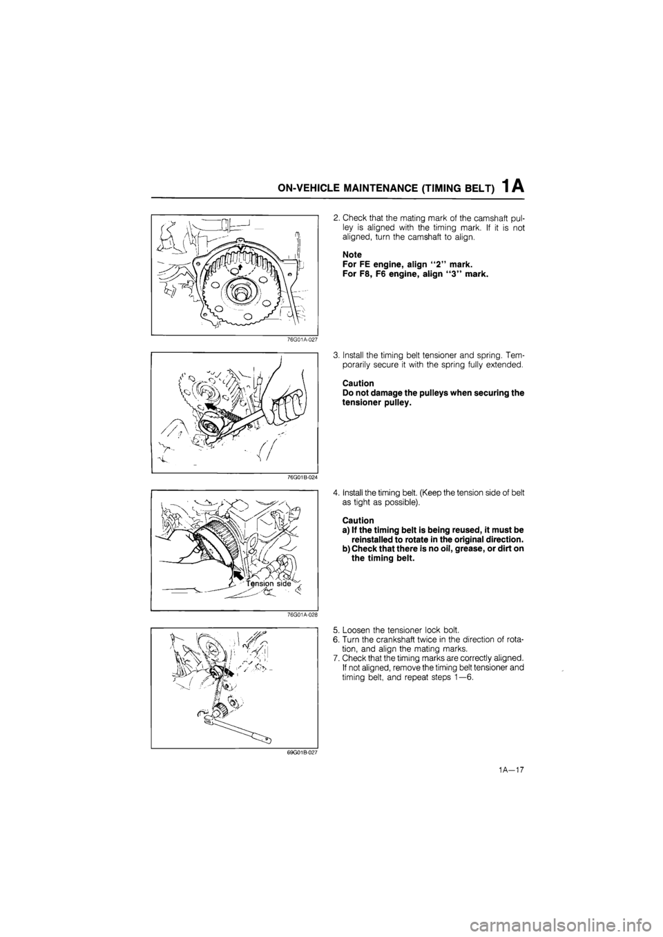
2. Check that the mating mark of the camshaft pul-
ley is aligned with the timing mark. If it is not
aligned, turn the camshaft to align.
Note
For FE engine, align "2" mark.
For F8, F6 engine, align "3" mark.
3. Install the timing belt tensioner and spring. Tem-
porarily secure it with the spring fully extended.
Caution
Do not damage the pulleys when securing the
tensioner pulley.
4. Install the timing belt. (Keep the tension side of belt
as tight as possible).
Caution
a) If the timing belt is being reused, it must be
reinstalled to rotate in the original direction.
b) Check that there is no oil, grease, or dirt on
the timing belt.
5. Loosen the tensioner lock bolt.
6. Turn the crankshaft twice in the direction of rota-
tion, and align the mating marks.
7. Check that the timing marks are correctly aligned.
If not aligned, remove the timing belt tensioner and
timing belt, and repeat steps 1—6.
69G01B-027
1A-17
Page 50 of 1865
1 A ON-VEHICLE MAINTENANCE (TIMING BELT)
8. Tighten the timing belt tensioner lock bolt.
Tightening torque:
37—52 N-m (3.8—5.3 m-kg, 27—38 ft-lb)
69G01B-028
9. Check the timing belt deflection. If the deflection
is not correct, repeat the adjustment from step 5
above.
Timing belt deflection
FE: 5.5—6.5 mm (0.22—0.26 in)
F8, F6: 4.0—5.0 mm (0.16—0.20 in)
/98 N (10 kg, 22 lb)
Caution
Be sure not to apply tension other than that
of the tensioner spring.
76G01A-029
Baffle plate
Install the baffle plate as shown in the figure.
69G01B-030
Drive belt
Install each drive belt, and check the belt deflection.
(Refer to page 1A—7.)
76G01A-030
1A—18
Page 51 of 1865
1 A ON-VEHICLE MAINTENANCE (TIMING BELT)
Spark plug
1. Apply anti-seize compound or molybdenum-based
lubricant to the spark plug threads.
2. Install the spark plugs.
Tightening torque:
15—23 N-m (1.5—2.3 m-kg, 11—17 ft-lb)
79G01C-021
Steps After Installation
Perform the necessary engine adjustment. (Refer to
TUNE-UP PROCEDURE.)
86U01X-029
1A—19
Page 52 of 1865
1 A ON-VEHICLE MAINTENANCE (CYLINDER HEAD)
CYLINDER HEAD
Removal
Warning: Release the fuel pressure. (Refer to Section 4.)
1. Disconnect the negative battery cable.
2. Drain the engine coolant.
3. Remove in the sequence shown in the figure referring to the removal note for specially marked parts.
76G01A-110
1A—20