Page 395 of 1865
4A FUEL SYSTEM
[FE 8Valve (Except General) and F6]
Assemble in the sequence shown in the figure, referring to the assembly note for specially marked parts.
1. Throttle body
2. Main body
3. Secondary ven-
turi and nozzle
4. Primary venturi
and nozzle
5. Injector weight
©Air bleeds and
jets
7. Solenoid valve
and idle switch
(If equipped)
8. Slow fuel cut
solenoid valve
9. Accelerator
pump
10. Needle valve
11. Secondary di-
aphragm
12. Float
13. Air horn, choke
breaker di-
aphragm, and
choke opener (If
equipped)
14. Lever
'3
©
76G04A-032
Assembly note
Air bleeds and jets
1. Step jet and plug
2. Secondary step air bleed (No. 1) (Fixed type)
3. Secondary main air bleed
4. Secondary main jet
5. Power jet
6. Primary main jet
7. Primary main air bleed
8. Primary slow air bleed (No. 1)
9. Primary slow jet and plug
10. Primary slow air bleed (No. 2)
76G04A-033
4A-30
Page 396 of 1865
FUEL SYSTEM 4A
76G04A-034
Inspection
Note
a) Clean all parts with carburetor cleaner and
dry with compressed air.
b) Do not use a wire to clean the jets.
Check the following and replace any faulty parts.
1. Damaged air horn, main body, or throttle body
2. Improper operation of the choke valve or throttle
valve
3. Damaged float
4. Needle valve damage or improper seating
5. Clogged or damaged jet or air bleed
6. Damaged piston cup in the accelerator pump
7. Weakened or broken spring
8. Damaged diaphragm
9. Improper solenoid operation
76G04A-191
Primary throttle valve
(0.248—0.327 in)
When secondary throttle valve
begins to open
Secondary Throttle Valve
1. Check the clearance between the primary throttle
valve and wall when lever A contacts lever B.
>
L_ Clearance:
7.3—8.3 mm (0.248—0.327 in)
7.3—8.3 mm
76G04A-035
3. If not within specification, adjust it by bending
lever A.
76G04A-036
4 A—31
Page 397 of 1865

4A FUEL SYSTEM
76G04A-037
Float Level
Caution
This adjustment must be made without the
gasket on the air horn.
1. Turn the air horn upside-down and allow the float
to lower by its own weight.
2. Measure clearance H between the float and the
air horn.
Clearance H: 12.5 mm (0.49 in)
3. If not as specified, bend the float seat lip A to adjust.
4. Turn the air horn to the normal position and allow
the float to lower by its own weight.
5. Measure clearance L between the bottom of the
float and the air horn.
Clearance L: 44 mm (1.73 in)
6. If not as specified, bend the float stop B to adjust.
76G04A-038
76G04A-039
Fast Opening
F6 and FE 8Valve (Except General)
1. With the choke valve fully closed, measure the
clearance between the primary throttle valve and
the wall of the throttle bore.
Specification:
Engine Spec. Clearance mm (in)
F6 General and
Singapore 1.40—1.76
(0.055-0.069) FE 8Valve Middle East and
Unleaded Fuel
1.40—1.76
(0.055-0.069)
2. If not within specification, carefully bend the con-
necting rod to adjust.
4A—32
Page 399 of 1865

4 A FUEL SYSTEM
76G04A-044
76G04A-045
76G04A-046
Choke Breaker Diaphragm
1. Warm up the engine to the normal operating tem-
perature, then stop the engine.
2. Set the choke valve to the fully closed position.
3. Apply 400 mmHg (15.7 inHg) vacuum to the di-
aphragm.
4. Measure the clearance between the choke valve
and air horn with a wire gauge.
Cl68r8ncG'
2.45—3.11 mm (0.096—0.122) FE, F8
1.68—2.14 mm (0.066—0.084 in) F6
5. If not within specification, adjust by bending the
lever.
Choke Opener
ECE, Hong Kong, Singapore, and Middle East
1. Warm up the engine to the normal operating tem-
perature, then stop the engine.
2. Set the choke valve to the fully closed position.
3. Apply 400 mmHg (15.7 InHg) vacuum to the di-
aphragm.
4. Measure the clearance between the choke valve
and air horn with a wire gauge.
Specification Clearance mm (in)
ECE, Hong Kong, and Singapore
(Except F6 MTX) 3.7—4.0 (0.15—0.16)
Middle East 3.3—3.6 (0.13—0.14)
F6 Singapore MTX 3.2—3.5 (0.13—0.14)
5. If not within specification, adjust by bending the
connecting rod.
76G04A-047
4A-34
Page 1309 of 1865
STEERING WHEEL AND COLUMN 1 0
STEERING WHEEL AND COLUMN
STRUCTURAL VIEW
76G10X-006
11. Steering shaft assembly
12. Intermediate shaft
13. Dust boot
1. Horn cap
2. Lock nut
3. Steering wheel
4. Column cover
5. Combination switch
6. Switch panel
7. Lower panel
8. Duct
9. Universal joint
10. Steering shaft
10—21
Page 1310 of 1865
1 0 STEERING WHEEL AND COLUMN
REMOVAL
1. Remove the horn cap.
2. Remove the locknut.
76G10X-007
3. The steering wheel must be removed with a suita-
ble puller.
Caution
Be careful not to subject the steering shaft to
severe impact in the axial direction when
removing or installing the steering wheel.
76G10X-008
4. Remove the column cover.
5. Disconnect the ignition switch connector.
6. Remove the combination switch.
76G10X-009
7. Remove the lower panel and switch panel.
8. Remove the duct.
76G10X-010
10-22
Page 1656 of 1865

15
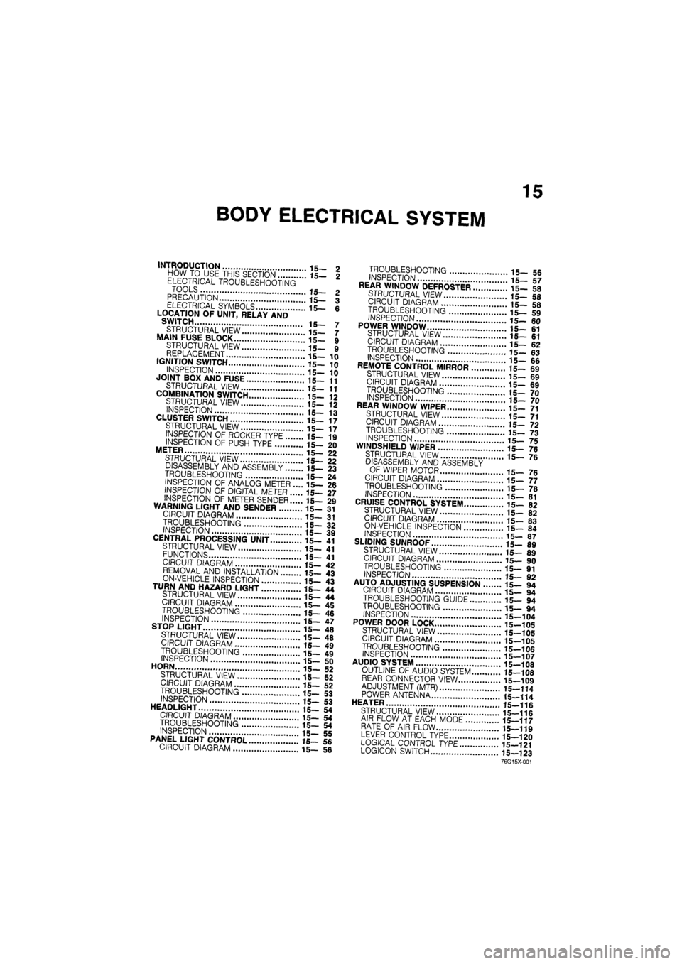
BODY ELECTRICAL SYSTEM
INTRODUCTION 15- 2 HOW TO USE THIS SECTION 15— 2 ELECTRICAL TROUBLESHOOTING TOOLS 15- 2 PRECAUTION 15— 3 ELECTRICAL SYMBOLS 15- 6 LOCATION OF UNIT, RELAY AND SWITCH 15- 7
STRUCTURAL VIEW 15— 7 MAIN FUSE BLOCK 15- 9 STRUCTURAL VIEW 15— 9 REPLACEMENT 15—10 IGNITION SWITCH 15—10
INSPECTION 15— 10 JOINT BOX AND FUSE 15—11
STRUCTURAL VIEW 15—11
COMBINATION SWITCH 15-12 STRUCTURAL VIEW 15- 12 INSPECTION 15— 13 CLUSTER SWITCH 15—17 STRUCTURAL VIEW 15— 17 INSPECTION OF ROCKER TYPE 15— 19
INSPECTION OF PUSH TYPE 15— 20 METER 15— 22 STRUCTURAL VIEW 15— 22 DISASSEMBLY AND ASSEMBLY 15— 23
TROUBLESHOOTING 15— 24 INSPECTION OF ANALOG METER .... 15— 26 INSPECTION OF DIGITAL METER 15— 27
INSPECTION OF METER SENDER 15— 29 WARNING LIGHT AND SENDER 15- 31 CIRCUIT DIAGRAM 15— 31
TROUBLESHOOTING 15- 32 INSPECTION 15— 39 CENTRAL PROCESSING UNIT 15— 41 STRUCTURAL VIEW 15— 41 FUNCTIONS 15- 41 CIRCUIT DIAGRAM 15— 42 REMOVAL AND INSTALLATION 15— 43
ON-VEHICLE INSPECTION 15- 43 TURN AND HAZARD LIGHT 15- 44 STRUCTURAL VIEW 15— 44 CIRCUIT DIAGRAM 15— 45
TROUBLESHOOTING 15- 46 INSPECTION 15— 47 STOP LIGHT 15— 48
STRUCTURAL VIEW 15— 48 CIRCUIT DIAGRAM 15— 49
TROUBLESHOOTING 15- 49 INSPECTION 15- 50 HORN 15— 52 STRUCTURAL VIEW 15— 52 CIRCUIT DIAGRAM 15— 52 TROUBLESHOOTING 15— 53 INSPECTION 15-53 HEADLIGHT 15— 54 CIRCUIT DIAGRAM 15— 54 TROUBLESHOOTING 15— 54 INSPECTION 15— 55 PANEL LIGHT CONTROL 15— 56 CIRCUIT DIAGRAM 15— 56
TROUBLESHOOTING 15_ 5fi INSPECTION 17 REAR WINDOW DEFROSTER ..i".'! 15- 58
STRUCTURAL VIEW 15-5fl CIRCUIT DIAGRAM 15_ «
TROUBLESHOOTING '.. 15_ 59
INSPECTION
15-60 POWER WINDOW 15-61 STRUCTURAL VIEW il_ «1 CIRCUIT DIAGRAM 15_ 62 TROUBLESHOOTING 15- «3 INSPECTION 15-66 REMOTE CONTROL MIRROR ........15- 69 STRUCTURAL VIEW 15-69 CIRCUIT DIAGRAM 15_ 69
TROUBLESHOOTING 15_ 70 INSPECTION 15_ 70 REAR WINDOW WIPER 15_ 71 STRUCTURAL VIEW 15-71 CIRCUIT DIAGRAM .'.'.'...' 15_ 72
TROUBLESHOOTING 15-73 INSPECTION 15-75 WINDSHIELD WIPER 15-76 STRUCTURAL VIEW ' ' 15— 7e
DISASSEMBLY AND ASSEMBLY OF WIPER MOTOR 15_ 76 CIRCUIT DIAGRAM 15-77 TROUBLESHOOTING " " 15— 70 INSPECTION 15-81 CRUISE CONTROL SYSTEM 15- 82 STRUCTURAL VIEW 15-82 CIRCUIT DIAGRAM 15-83 ON-VEHICLE INSPECTION \..\m 15- 84 INSPECTION 15-87 SLIDING SUNROOF 15-89 STRUCTURAL VIEW 15_ 89 CIRCUIT DIAGRAM i5_ 90
TROUBLESHOOTING 15— 91 INSPECTION 15_ 90 AUTO ADJUSTING SUSPENSION 15— 94
CIRCUIT DIAGRAM 15- 94
TROUBLESHOOTING GUIDE 15— 94
TROUBLESHOOTING 15— 94
INSPECTION 15-104
POWER DOOR LOCK 15-105
STRUCTURAL VIEW 15-105
CIRCUIT DIAGRAM 15-105
TROUBLESHOOTING 15-106 INSPECTION 15-107 AUDIO SYSTEM " 15_108 OUTLINE OF AUDIO SYSTEM 15-108 REAR CONNECTOR VIEW 15-109 ADJUSTMENT (MTR) 15—114 POWER ANTENNA 15-114 HEATER J
STRUCTURAL VIEW 15-116 AIR FLOW AT EACH MODE 15-117 RATE OF AIR FLOW 15-119 LEVER CONTROL TYPE 15-120 LOGICAL CONTROL
TYPE
15—121 LOGICON SWITCH 15—123
76G15X-001
Page 1666 of 1865

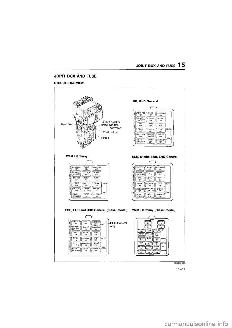
JOINT
BOX AND FUSE
1
5
JOINT BOX AND FUSE
STRUCTURAL VIEW
Joint box Circuit breaker
(Rear window
defroster)
Reset button
Fuses
West Germany
(REAR FOG* RADIO 15A 15A (HEADCLEANER) 20A
(POWER 30A WIND) TAIL (LH) 15A STOP 15A
TAIL (RH) 15A METER 15A TURN 15A
ROOM 15A f(D00R LOCK) [ 30A c
HORN 5A
(AIR COND)' 15A (COOLING 20A FAN>I ENGINE 15A
(REAR 15A WIPER) WIPER 20A (SUN ROOF) [ 15A
ECE, LHD and RHD General (Diesel model)
. Q .
(REAR FOG) 15A J RADIO 15A (rHEADCLEAMEfii I joa J (POWER 1 30A WIND)j (DIM DIP) 15A ( HAZAARD ' I TAIL 15A METER 15A TURN 15A
' ROOM ' ISA j flBOOR LOCKl"1 L STOP 1SA -[(AIR COND) 15A J ' ENGINE 15A
(REAR 15A WIPER) WIPER 20A (SUN ROOF) I 16A
RHD General
only
UK, RHD General
(REAR FOG)
[
15A J
RADIO 15A (HEADCLEANER) 20A
(POWER 30A WIND) (DIM DIP) 15A HAZARD 10A
TAIL 15A METER 10A TURN 15A
ROOM 15A (DOOR LOCK) 30A STOP 15A
(AIR COND) 15A '(COOLING 20A FAN) ENGINE 15A
(REAR 15A WIPER) WIPER 20A (SUN ROOF) [ 15A ,
ECE, Middle East, LHD General
Q
(REAR FOG) 15A J RADIO 15A (HEADCLEANER) 20A
(POWER 30A WIND) HAZARD 10A
TAIL 15A METER 15A TURN 15A
ROOM 5A (DOOR LOCK) 3CA STOP tSA ] (AIR CONO)| . ISA jj| ((COOLING! ( ENGINE 1 J [
BOA
FAfJ)J [ 15A J
(REAR 15AWIP£R), ^ C WIPER "1[SUN HOOF?
1)J
[ 2QA
J
[ 15A
West Germany (Diesel model)
MAIN (fWl
ISA I
MALM (LM1
15A
DIM iLHI
ISA
PEAfl FOCii
I 'SA | RAQIO T5A I
HEAP CLEANEF*
1 I (POWEfl I
3PA WI^D;. TAIL (LH)
15A
)C
TAIL
I ISA METER 1OA TURN 15A FIOQM
(DOOR LOC*C|
HOflN 15A Jt 1SA
(
AIR COND)
jy (COOUNQ
gqA FAN)
ENGINE 16A
|fl£AR WlPEFl!
ILJSi '
DEfOO
3 OA
Dtf
WtPEfl
USUNROQF Jl JPA H 15A [
86U15X-006
15-11