Page 915 of 1865
TROUBLESHOOTING (G4A-HL) 7B
STEP 3 (STALL TEST)
This step is performed to determine if there is slippage of the friction elements or malfunction of the
hydraulic components.
Preparation
Check the following items prior to testing:
1. Engine coolant, engine oil and ATF levels.
2. Warm the engine thoroughly to raise the ATF temperature to operating level (50—80°C, 122—176°F).
3. Engage the parking brake and use wheel chocks at the front and rear wheels.
Pull the parking brake Water temperature
ATF
83U07B-038
7B—49
Page 919 of 1865

TROUBLESHOOTING (G4A-HL) 7B
STEP 5 (ROAD TEST)
This step is performed to inspect for problems at the various ranges.
If
these tests show any problems,
adjust or replace by referring to the mechanical sections.
Perform the test at normal ATF operating temperature (50—80°C, 122—176°F).
D Range Test
Shift point, shift pattern, and shift shock
1. Shift the selector lever to D range and depress the OD OFF switch.
2. Accelerate the vehicle with half (4/8) and full (8/8) throttle valve opening.
3. Check that 1-2, 2-3 and 3-OD up-shifts and downshifts and lock-up are obtained. The shift points
must be as shown in the D range shift diagram.
Note
a) Vehicle speed on a chassis roller may not meet the specified shift diagram because of
tire size.
b) There is no lock-up or OD when the coolant temperature is below 72°C (162°F), and when
the OD OFF switch is depressed.
4. Check the up and down shifts for shift shock or slippage.
5. While driving in 3rd (50—60 km/h, 31—37 mph) shift the selector lever to 2 range and check that
3-2 downshift immediately occurs, then decelerate and check that engine braking effect is felt in
2nd gear.
D range shift diagram
FE engine
Caution
8/8 n
-OD
0 20(12) 40(25) 60(37) 80(50) 100(63) 120(74) 140(87)
Vehicle speed km/h (mph)
76GC7B-057
7B—53
Page 1128 of 1865
7C TROUBLESHOOTING
STEP 2 (STALL TEST)
This step is performed to determine if there is slippage of the friction elements or malfunction of the
hydraulic components.
Preparation
Check the following items prior to testing:
1. Engine coolant, engine oil and ATF levels.
2. Warm the engine thoroughly to raise the ATF temperature to operating level (50—80°C, 122—176°F).
3. Set the parking brake and block the front and rear of the wheels.
Pull the parking brake Water temperature
ATF
7C—14
76G07C-024
Page 1648 of 1865
HEADLIGHT WASHER 14
HEADLIGHT WASHER
REMOVAL AND INSTALLATION
1. Remove in the sequence shown in the figure.
2. Install in the reverse order of removal.
76G14X-039
1. Bracket
2. Coolant reservoir
3. Bracket
4. Washer pump
5. Washer nozzles
6. Clips
7. Hose
8. Joint
9. Washer tank
14—97
Page 1694 of 1865
WARNING AND SENDER 15
Coolant Level Warning Light
OK
Repair harness (Meter
to
coolant level sensor).
76G15X093
INSPECTION
Brake Fluid Level Sensor
1. Check for continuity of the sensor with an
ohmmeter.
Float level Continuity
Below
min
Yes
Above
min
No
2. If continuity is not as specified, replace the sensor.
86U15X-065
86U14X-066
Parking Brake Switch
1. Check for continuity between (R) terminal and a
body ground with an ohmmeter.
Lever Continuity
Pulled one notch Yes
Released No
2. If continuity is not as specified, adjust the switch
or replace the switch.
15—39
Page 1695 of 1865
15 WARNING AND SENDER
86U15X-068
86U15X069
86U15X-070
Door Switch
1. Check for continuity of the switch with an
ohmmeter.
2. If continuity is not as specified, replace the switch.
Washer Level Sensor
1. Check for continuity between C (LY) terminal and
D (B) terminal of the washer level sensor con-
nector.
Oil Pressure Switch
1. Disconnect the connector from the oil pressure
switch.
2. Check for continuity between the switch and a
body ground with each condition.
Coolant Level Sensor
1. Remove the level sensor and connect the con-
nector.
2. With the sensor not grounded to the body, start
the engine.
3. After checking that the warning light illuminates,
ground the threaded part of the sensor.
4. If the warning light remains illuminated, the sen-
sor is faulty and replace it.
73G15X-013
15—40
Engine Continuity
Running Yes
Stop No
Terminals Float level Continuity
C (LY)—D
(B)
Bottom Yes C (LY)—D
(B)
Above bottom No
2. If continuity is not as specified, replace the sensor.
Page 1830 of 1865

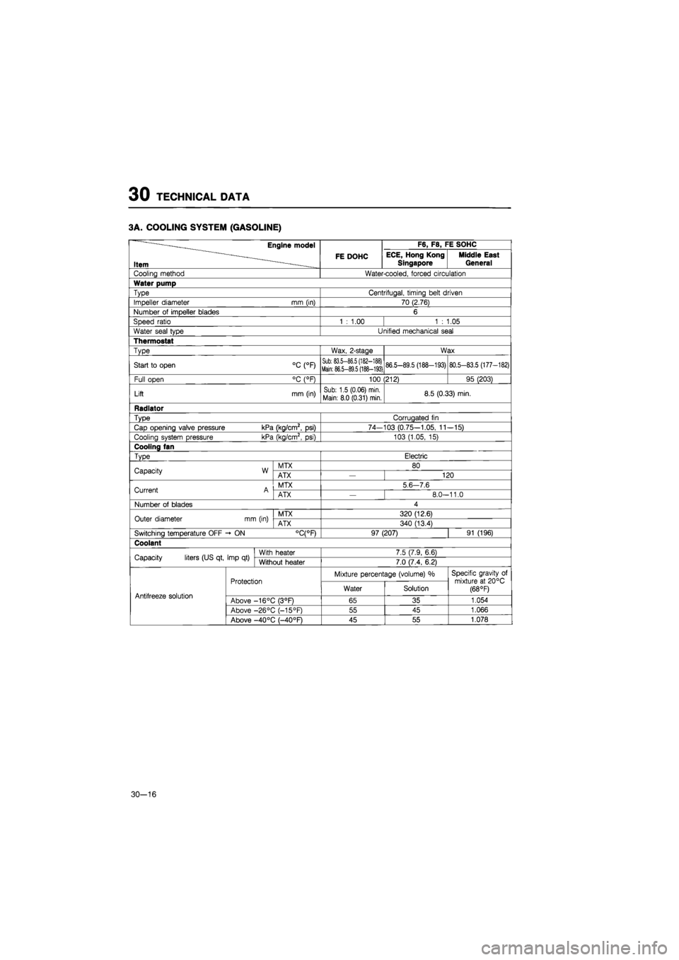
30 TECHNICAL DATA
3A. COOLING SYSTEM (GASOLINE)
Engine model F6, F8, FE SOHC
Item FE DOHC ECE, Hong Kong
Singapore Middle East General
Cooling method Water-cooled, forced circulation
Water pump
Type Centrifugal, timing belt driven
Impeller diameter mm (in) 70 (2.76)
Number
of
impeller blades 6
Speed ratio 1
:
1.00 1
:
1.05
Water seal type Unified mechanical seal
Thermostat
Type Wax, 2-stage Wax
Start
to
open °C (°F) Sub: 83.5-86.5 (182-188) Main: 86.5-89.5 (188-193) 86.5-89.5 (188-193) 80.5-83.5 (177-182)
Full open °C (°F) 100 (212) 95 (203)
Lift mm (in) Sub: 1.5 (0.06) min.
Main: 8.0 (0.31) min. 8.5 (0.33) min.
Radiator
Type Corrugated
fin
Cap opening valve pressure kPa (kg/cm2,
psi)
74-103 (0.75-1.05,
11
-15)
Cooling system pressure kPa (kg/cm2,
psi)
103 (1.05,
15)
Cooling fan
Type Electric
Capacity W MTX 80 Capacity W ATX 120
Current A MTX 5
6 7.6
Current A ATX
—
8.0-11.0
Number
of
blades 4
Outer diameter mm (in) MTX 320 (12.6) Outer diameter mm (in) ATX 340 (13.4)
Switching temperature OFF -
ON
°C(°F) 97 (207) 91 (196)
Coolant
Capacity liters (US qt, Imp
qt)
With heater 7.5 (7.9, 6.6) Capacity liters (US qt, Imp
qt)
Without heater 7.0 (7.4, 6.2)
Protection Mixture percentage (volume)
%
Specific gravity
of
mixture
at
20°C (68 °F) Antifreeze solution
Protection Water Solution
Specific gravity
of
mixture
at
20°C (68 °F) Antifreeze solution Above -16°C (3°F) 65 35 1.054
Above -26°C (-15°F) 55 45 1.066
Above -40 °C (—40°F) 45 55 1.078
30-16
Page 1831 of 1865

TECHNICAL DATA 30
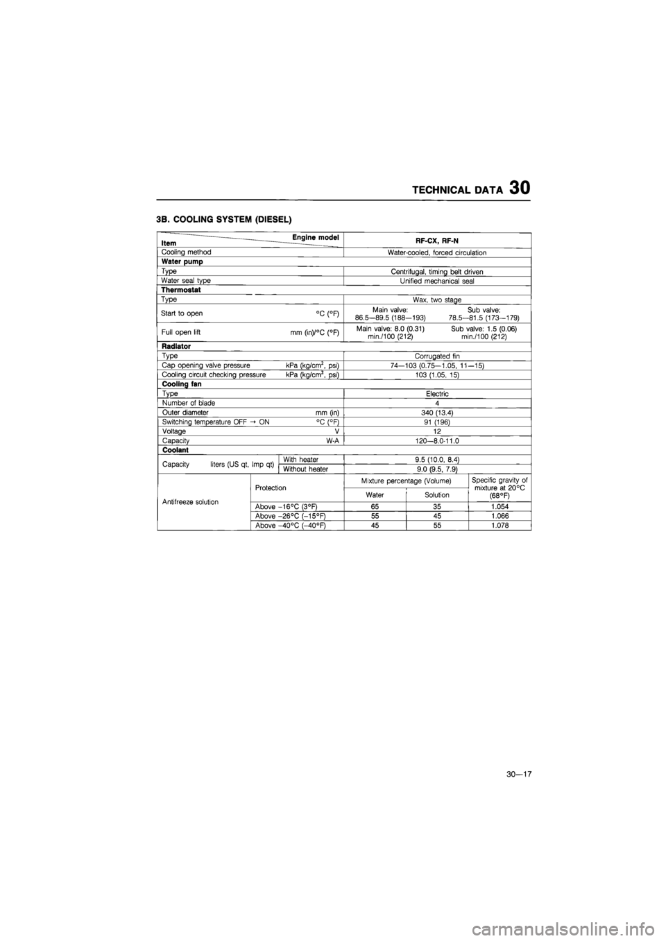
3B. COOLING SYSTEM (DIESEL)
Item Engine model RF-CX, RF-N
Cooling method Water-cooled, forced circulation
Water pump
Type Centrifugal, timing belt driven
Water seal type Unified mechanical seal
Thermostat
Type Wax, two stage
Start
to
open °C (°F) Main valve:
86.5-89.5 (188-193)
78.5-
Sub valve: 81.5 (173-179)
Full open lift mm (in)/°C (°F) Main valve: 8.0 (0.31) Sub valve: 1.5 (0.06) min./100 (212) min./100 (212)
Radiator
Type Corrugated
fin
Cap opening valve pressure kPa (kg/cm2,
psi)
74—103 (0.75—1.05,
11
-15)
Cooling circuit checking pressure kPa (kg/cm2,
psi)
103 (1.05,
15)
Cooling fan
Type Electric
Number
of
blade 4
Outer diameter mm (in) 340 (13.4)
Switching temperature OFF -»
ON
°C (°F) 91 (196)
Voltage V 12
Capacity W-A 120-8.0-11.0
Coolant
Capacity liters (US qt, Imp
qt)
With heater 9.5 (10.0, 8.4) Capacity liters (US qt, Imp
qt)
Without heater 9.0 (9.5, 7.9)
Protection Mixture percentage (Volume) Specific gravity
of
mixture
at
20°C (68 °F) Antifreeze solution
Protection Water Solution
Specific gravity
of
mixture
at
20°C (68 °F) Antifreeze solution Above -16°C (3°F) 65 35 1.054
Above -26°C (-15°F) 55 45 1.066
Above -40°C (-40°F) 45 55 1.078
30-17