Page 827 of 3115
F08298
STP
(-) (+)
- DIAGNOSTICSABS & VEHICLE STABILITY CONTROL (VSC) &
BRAKE ASSIST (BA) SYSTEMDI-575
768 Author�: Date�:
2004 LAND CRUISER (RM1071U)
INSPECTION PROCEDURE
1 Check operation of the stop light switch.
CHECK:
Check that the stop light lights up when the brake pedal is depressed and goes OFF when the brake pedal
is released.
OK Go to step 3.
NG
2 Check stop light circuit (See page BE-50).
NG Check stop light bulb and repair or replace stop
light circuit.
OK
3 Check voltage between terminal STP of skid control ECU and body ground.
PREPARATION:
Remove the skid control ECU with connectors still connected.
CHECK:
Measure voltage between terminal STP of the skid control ECU
and body ground when the brake pedal is depressed.
OK:
Voltage: 10 to 14 V
OK Proceed to next circuit inspection shown in
problem symptoms table (See page IN-36).
NG
Page 828 of 3115
DI-576- DIAGNOSTICSABS & VEHICLE STABILITY CONTROL (VSC) &
BRAKE ASSIST (BA) SYSTEM
769 Author�: Date�:
2004 LAND CRUISER (RM1071U)
4 Check for open circuit in harness and connector between skid control ECU and
stop light switch (See page IN-36).
NG Repair or replace harness or connector.
OK
Check and replace skid control ECU.
Page 834 of 3115
 &
BRAKE ASSIST (BA) SYSTEM
775 Author�: Date�:
2004 LAND CRUISER (RM1071U)
4 Check pressure switch (PH).
In case of usi")
F02861
LOCKON
PH
PHG
DI-582- DIAGNOSTICSABS & VEHICLE STABILITY CONTROL (VSC) &
BRAKE ASSIST (BA) SYSTEM
775 Author�: Date�:
2004 LAND CRUISER (RM1071U)
4 Check pressure switch (PH).
In case of using the hand-held tester:
PREPARATION:
(a) Connect the hand-held tester to the DLC3.
(b) Turn the ignition switch ON and push the hand-held tester main switch ON.
(c) Select the DATA LIST mode on the hand-held tester.
CHECK:
Depress the brake pedal more than 40 times with the ignition switch OFF, then turn the ignition switch ON
and check the pressure switch (PH) condition.
HINT:
When pressure in the power supply system is released, reaction force becomes light and stroke becomes
longer.
OK:
ºOFFº turns to ºONº.
HINT:
OFF: Low pressure
ON: High pressure
In case of not using the hand-held tester:
PREPARATION:
(a) Disconnect the connector (5P) from the hydraulic brake
booster.
(b)
With the ignition switch OFF, depress the brake pedal more than
40 times to decrease the accumulator pressure.
HINT:
When pressure in the power supply system is released, reac-
tion force becomes light and stroke becomes longer.
CHECK:
Measure resistance between terminals PH and PHG of the hy-
draulic brake booster connector.
OK:
Resistance: 1.0 kW
PREPARATION:
(a) Connect the connector (5P) to the hydraulic brake boost-
er.
(b) Disconnect the connector (5P) after the ignition switch is
turned ON and the pump motor is stopped.
CHECK:
Measure resistance between terminals PH and PHG of the hy-
draulic brake booster connector.
OK:
Resistance: 0 W
HINT:
After inspection, connect the connector and clear the DTC (See
page DI-505).
NG Replace hydraulic brake booster assembly.
Page 835 of 3115
 &
BRAKE ASSIST (BA) SYSTEMDI-583
776 Author�: Date�:
2004 LAND CRUISER (RM1071U)
OK
5 Check pressure switch (PL).
In case of")
F02863
LOCK
ONPL
PLG
- DIAGNOSTICSABS & VEHICLE STABILITY CONTROL (VSC) &
BRAKE ASSIST (BA) SYSTEMDI-583
776 Author�: Date�:
2004 LAND CRUISER (RM1071U)
OK
5 Check pressure switch (PL).
In case of using hand-held tester:
PREPARATION:
(a) Connect the hand-held tester to the DLC3.
(b) Turn the ignition switch ON and push the hand-held tester main switch ON.
(c) Select the DATA LIST mode on the hand-held tester.
CHECK:
Depress the brake pedal more than 40 times with the ignition switch OFF, then turn the ignition switch ON
and check the pressure switch (PL) condition.
HINT:
When pressure in the power supply system is released, reaction force becomes light and stroke becomes
longer.
OK:
ºOFFº turns to ºONº.
HINT:
OFF: Low pressure
ON: High pressure
In case of not using hand-held tester:
PREPARATION:
(a) Disconnect the connector (8P) from the hydraulic brake
booster.
(b) With the ignition switch OFF, depress the brake pedal
more than 40 times to decrease the accumulator pres-
sure.
HINT:
When pressure in the power supply system is released, reac-
tion force becomes light and stroke becomes longer.
CHECK:
Measure resistance between terminals PL and PLG of the hy-
draulic brake booster connector.
OK:
Resistance: 5.7 kW
PREPARATION:
(a) Connect the connector (8P) to the hydraulic brake boost-
er.
(b) Disconnect the connector (8P) after the ignition switch is
turned ON and the pump motor is stopped.
CHECK:
Measure resistance between terminals PL and PLG of the hy-
draulic brake booster connector.
OK:
Resistance: 1.0 kW
Page 845 of 3115
F09987
LOCK
PLGPL
- DIAGNOSTICSABS & VEHICLE STABILITY CONTROL (VSC) &
BRAKE ASSIST (BA) SYSTEMDI-593
786 Author�: Date�:
2004 LAND CRUISER (RM1071U)
INSPECTION PROCEDURE
1 Check pressure switch (PL) resistance.
PREPARATION:
(a) Disconnect the connector (8P) from the hydraulic brake
booster.
(b) With the ignition switch OFF, depress the brake pedal
more than 40 times to decrease the accumulator pres-
sure.
HINT:
When pressure in the power supply system is released, reac-
tion force becomes light and stroke becomes longer.
CHECK:
Measure resistance between terminals PL and PLG of the hy-
draulic brake booster connector.
OK:
Resistance: 5.1 to 6.3 kW
HINT:
After inspection, connect the connector and clear the DTC (See
page DI-505).
NG Replace hydraulic brake booster assembly.
OK
Page 846 of 3115
F06043
LOCK
PH
PHG
DI-594- DIAGNOSTICSABS & VEHICLE STABILITY CONTROL (VSC) &
BRAKE ASSIST (BA) SYSTEM
787 Author�: Date�:
2004 LAND CRUISER (RM1071U)
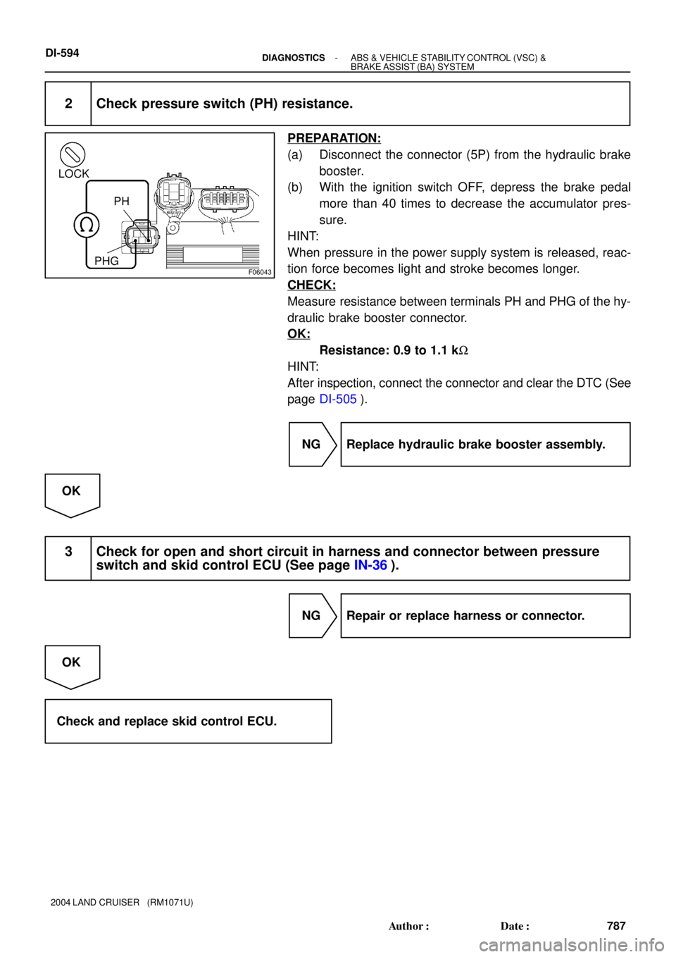
2 Check pressure switch (PH) resistance.
PREPARATION:
(a) Disconnect the connector (5P) from the hydraulic brake
booster.
(b) With the ignition switch OFF, depress the brake pedal
more than 40 times to decrease the accumulator pres-
sure.
HINT:
When pressure in the power supply system is released, reac-
tion force becomes light and stroke becomes longer.
CHECK:
Measure resistance between terminals PH and PHG of the hy-
draulic brake booster connector.
OK:
Resistance: 0.9 to 1.1 kW
HINT:
After inspection, connect the connector and clear the DTC (See
page DI-505).
NG Replace hydraulic brake booster assembly.
OK
3 Check for open and short circuit in harness and connector between pressure
switch and skid control ECU (See page IN-36).
NG Repair or replace harness or connector.
OK
Check and replace skid control ECU.
Page 849 of 3115

(+)
(-)
(+)
BM2
BM1EM1 EM2
- DIAGNOSTICSABS & VEHICLE STABILITY CONTROL (VSC) &
BRAKE ASSIST (BA) SYSTEMDI-597
790 Author�: Date�:
2004 LAND CRUISER (RM1071U)
INSPECTION PROCEDURE
1 Chec")
F02859
(-)
(+)
(-)
(+)
BM2
BM1EM1 EM2
- DIAGNOSTICSABS & VEHICLE STABILITY CONTROL (VSC) &
BRAKE ASSIST (BA) SYSTEMDI-597
790 Author�: Date�:
2004 LAND CRUISER (RM1071U)
INSPECTION PROCEDURE
1 Check accumulator operation.
PREPARATION:
(a) Turn the ignition switch OFF, and depress the brake pedal 40 times or more.
HINT:
When pressure in the power supply system is released, reaction force becomes light and stroke becomes
longer.
(b) Install the LSPV gauge (SST) to the rear brake caliper and bleed air.
SST 09709-29018
CHECK:
Depress the brake pedal with a force of more than 294 N (30 kgf, 66 lbf) and turn the ignition switch ON, then
check the rear brake caliper pressure when an increase of pressure changes from acutely to mildly.
OK:
5,099 to 8,924 kPa (52 to 91 kgf/cm2, 740 to 1,294 psi) at 20°C (68°F)
HINT:
If the value is not within the standard, cool the engine room and check it again.
NG Replace accumulator.
OK
2 Check operation of hydraulic brake booster pump motor.
PREPARATION:
Disconnect the 2 connectors from the hydraulic brake booster.
CHECK:
Connect the battery positive � lead to BM1 or BM2 terminal
and the battery negative � lead to EM1 or EM2 terminal of the
hydraulic brake booster (pump motor) connector.
OK:
The operation sound of the pump motor should be
heard.
NG Go to step 7.
OK
Page 850 of 3115
 &
BRAKE ASSIST (BA) SYSTEM
791 Author�: Date�:
2004 LAND CRUISER (RM1071U)
3 Check pressure switch (")
F04506
LOCKON
PH
PHG
F06043
LOCK
PH
PHG
DI-598- DIAGNOSTICSABS & VEHICLE STABILITY CONTROL (VSC) &
BRAKE ASSIST (BA) SYSTEM
791 Author�: Date�:
2004 LAND CRUISER (RM1071U)
3 Check pressure switch (PH) operation.
PREPARATION:
(a) Turn the ignition switch OFF, and depress the brake pedal
40 times or more.
HINT:
When pressure in the power supply system is released, reac-
tion force becomes light and stroke becomes longer.
(b) Install the LSPV gauge (SST) to the rear brake caliper
and bleed air.
SST 09709-29018
CHECK:
While checking the voltage between terminals PH and PHG of
the hydraulic brake booster, depress the brake pedal with a
force of more than 294 N (30 kgf, 66 lbf) and turn the ignition
switch ON, then check the rear wheel cylinder pressure when
voltage changes from 6 V to 0 V.
OK:
12,553 to 20,104 kpa (128 to 205 kgf´cm2, 1,820 to
2,916 psi)
PREPARATION:
Turn the ignition switch OFF and disconnect the connector (5P)
from the hydraulic brake booster.
CHECK:
While checking the resistance between terminals PH and PHG,
depress the brake pedal changing the force in a range of 197
N (20 kgf, 44 lbf) to 294 N (30 kgf, 66 lbf) and check the rear
wheel cylinder pressure when resistance changes from 0 kW to
1 kW between PH and PHG.
OK:
11,964 to 18,240 kpa (122 to 186 kgf´cm2, 1,735 to
2,645 psi)
HINT:
After inspection, connect the connector, fill brake reservoir with
brake fluid and clear the DTC (See page DI-505).
OK Go to step 5.
NG