Page 523 of 3115

(l) Observe the procedure in step (k) and bleed left rear
brake line.
(m) Disconnect the actuator checker (SST) and s")
F04458
BR-8
- BRAKEBRAKE FLUID
2144 Author�: Date�:
2004 LAND CRUISER (RM1071U)
(l) Observe the procedure in step (k) and bleed left rear
brake line.
(m) Disconnect the actuator checker (SST) and sub-wire har-
ness (SST) from the actuator.
SST 09990-00150, 09990-00480
(n) Connect the 2 connectors to the hydraulic brake booster.
(o) Clear the DTC (See page DI-505).
4. BLEED BRAKE LINE
(a) Connect the vinyl tube to the brake caliper.
(b) Depress the brake pedal several times, then loosen the
bleeder plug with the pedal held down.
(c) At the point when fluid stops coming out, tighten the
bleeder plug, then release the brake pedal.
(d) Repeat (b) and (c) until all the air in the fluid has been bled
out.
(e) Repeat the above procedure to bleed the brake line for
each wheel.
Torque: 11 N´m (110 kgf´cm, 8 ft´lbf)
5. CHECK FLUID LEVEL IN RESERVOIR
(a) With the ignition switch OFF, depress the brake pedal
more than 40 times.
HINT:
When a pressure in power supply system is released, reaction
force becomes light and stroke becomes longer.
(b) Remove the reservoir cap. Add brake fluid up to the
ºMAXº line.
Fluid: SAE J1703 or FMVSS NO. 116 DOT3
Page 524 of 3115
BR0X9-02
F08309
Pedal Pad Brake PedalReturn Spring
Cowl Side TrimLower No. 1 PanelLH Lower Panel
No. 2 Heater to Register Duct
ABS ECU or
ABS & BA & TRAC
& VSC ECU
N´m (kgf´cm, ft´lbf): Specified torque
Cushion
Stop Light Switch
20 (200, 14)
Hydraulic Brake Booster Assembly
MP Grease
Front Door Scuff Plate
5.0 (51, 44 in.´lbf)
Clevis PinClip
- BRAKEBRAKE PEDAL
BR-1 1
2147 Author�: Date�:
2004 LAND CRUISER (RM1071U)
COMPONENTS
Page 525 of 3115
BR0XB-02
F06414
- BRAKEBRAKE PEDAL
BR-13
2149 Author�: Date�:
2004 LAND CRUISER (RM1071U)
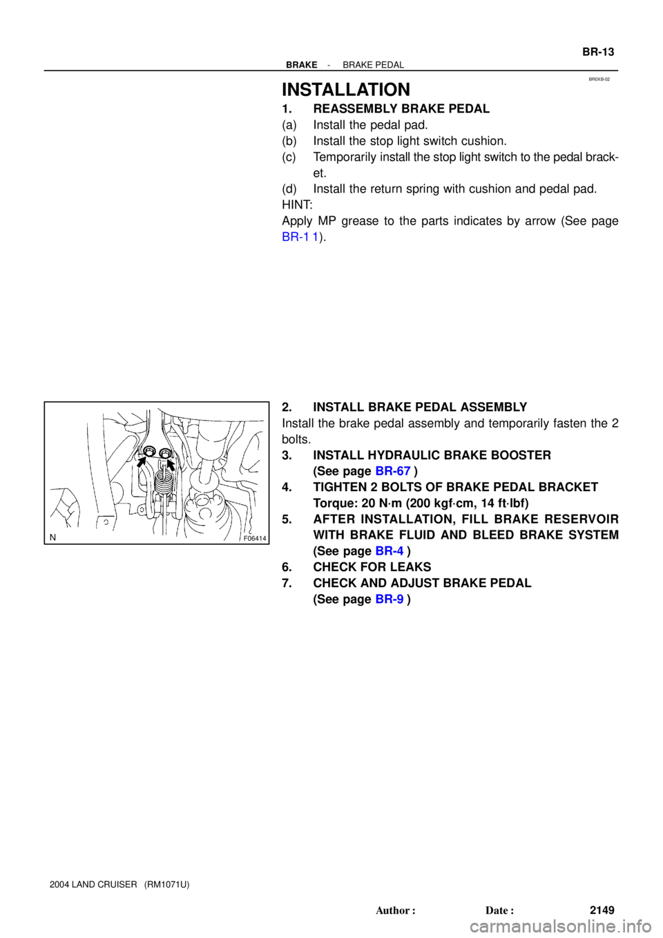
INSTALLATION
1. REASSEMBLY BRAKE PEDAL
(a) Install the pedal pad.
(b) Install the stop light switch cushion.
(c) Temporarily install the stop light switch to the pedal brack-
et.
(d) Install the return spring with cushion and pedal pad.
HINT:
Apply MP grease to the parts indicates by arrow (See page
BR-1 1).
2. INSTALL BRAKE PEDAL ASSEMBLY
Install the brake pedal assembly and temporarily fasten the 2
bolts.
3. INSTALL HYDRAULIC BRAKE BOOSTER
(See page BR-67)
4. TIGHTEN 2 BOLTS OF BRAKE PEDAL BRACKET
Torque: 20 N´m (200 kgf´cm, 14 ft´lbf)
5. AFTER INSTALLATION, FILL BRAKE RESERVOIR
WITH BRAKE FLUID AND BLEED BRAKE SYSTEM
(See page BR-4)
6. CHECK FOR LEAKS
7. CHECK AND ADJUST BRAKE PEDAL
(See page BR-9)
Page 526 of 3115

BRAKE PEDAL
ON-VEHICLE INSPECTION
1. CHECK PED")
F09171
Stop Light Switch Push Rod
Pedal Height
BR0JB-08
F02849
Pedal Freeplay
- BRAKEBRAKE PEDAL
BR-9
2145 Author�: Date�:
2004 LAND CRUISER (RM1071U)
BRAKE PEDAL
ON-VEHICLE INSPECTION
1. CHECK PEDAL HEIGHT
Pedal height from asphalt sheet:
183.7 - 193.7 mm (7.232 - 7.626 in.)
If the pedal height is incorrect, adjust it.
2. IF NECESSARY, ADJUST PEDAL HEIGHT
(a) Remove the scuff plate, cowl side trim, lower No. 1 panel,
LH lower panel and No. 2 heater to register duct (See
page BO-81).
(b) Remove the steering wheel pad, steering wheel lower
No. 2 and No. 3 covers, steering wheel, combination
switch, column upper and lower covers, steering column
assembly and thrust stopper (See page SR-14 or
SR-29).
(c) Disconnect the connector from the stop light switch.
(d) Loosen the stop light switch lock nut and remove the stop
light switch.
(e) Loosen the push rod lock nut.
(f) Adjust the pedal height by turning the pedal push rod.
(g) Tighten the push rod lock nut.
Torque: 25 N´m (260 kgf´cm, 19 ft´lbf)
(h) Install the stop light switch.
(i) Connect the connector to the stop light switch.
(j) Push in the brake pedal 5 - 15 mm (0.20 - 0.59 in.), turn
the stop light switch to lock the nut in the position where
the stop light goes off.
(k) After installation, push in the brake pedal 5 - 15 mm (0.20
- 0.59 in.), check that stop light lights up.
(l) After adjusting the pedal height, check the pedal freeplay.
(m) Install the thrust stopper, steering column assembly, col-
umn upper and lower covers, combination switch, steer-
ing wheel, steering wheel lower No. 2 and No. 3 covers,
and steering wheel pad (See page SR-14 or SR-29).
(n) Install the No. 2 heater to register duct, LH lower panel,
lower No. 1 panel, cowl side trim and scuff plate (See
page BO-81).
3. CHECK PEDAL FREEPLAY
(a) Stop the engine and depress the brake pedal more than
40 times until there is no more pressure left in the booster.
(b) Push in the pedal by hand until the second point of resis-
tance begins to be felt, then measure the distance, as
shown.
Pedal freeplay: 1.0 - 6.0 mm (0.039 - 0.236 in.)
Page 527 of 3115
F02850Pedal Reserve Distance BR-10
- BRAKEBRAKE PEDAL
2146 Author�: Date�:
2004 LAND CRUISER (RM1071U)
If incorrect, check the stop light switch clearance. If the clear-
ance is OK, then troubleshoot the brake system.
Stop light switch clearance: 1.9 mm (0.075 in.)
HINT:
The freeplay to the 1st point of resistance is due to the play be-
tween the clevis, pedal link and pin. It is 1.0 - 6.0 mm (0.039 -
0.236 in.) on the pedal.
4. CHECK PEDAL RESERVE DISTANCE
(a) Remove the floor carpet.
(b) Release the parking brake.
With the engine running, depress the pedal and measure
the pedal reserve distance, as shown.
Pedal reserve distance at 490 N (50 kgf, 110.1 lbf):
More than 116 mm (4.57 in.)
If the reserve distance is incorrect, troubleshoot the brake sys-
tem.
Page 528 of 3115
BR0XA-02
F06414
BR-12
- BRAKEBRAKE PEDAL
2148 Author�: Date�:
2004 LAND CRUISER (RM1071U)
REMOVAL
1. REMOVE HYDRAULIC BRAKE BOOSTER ASSEMBLY
(See page BR-60)
2. REMOVE BRAKE PEDAL ASSEMBLY
(a) Disconnect the connector from the stop light switch.
(b) Remove the 2 bolts.
(c) Remove the brake pedal assembly.
3. DISASSEMBLY BRAKE PEDAL ASSEMBLY
(a) Remove the return spring with cushion.
(b) Remove the stop light switch.
(c) Remove the pedal pad.
Page 549 of 3115

HYDRAULIC BRAKE BOOSTER
ON-VEHICLE INSPECTION
1. CHECK HYDRAUL")
F04470
Brake Pedal Effort Gauge
SST
SST
BR12B-07
BR-40
- BRAKEHYDRAULIC BRAKE BOOSTER
2176 Author�: Date�:
2004 LAND CRUISER (RM1071U)
HYDRAULIC BRAKE BOOSTER
ON-VEHICLE INSPECTION
1. CHECK HYDRAULIC BRAKE BOOSTER FLUID PRES-
SURE CHANGE
(a) Inspect the battery positive voltage.
Battery positive voltage: 10 - 14 V
(b) Turn the ignition switch OFF, depress the brake pedal
more than 40 times.
HINT:
When a pressure in power supply system is released, reaction
force becomes light and stroke becomes longer.
(c) Install LSPV gauge (SST) and brake pedal effort gauge,
bleed air.
SST 09709-29018
(d) When booster does not operate:
Depress the brake pedal and check fluid pressure.
At 245 N (25 kgf, 55 lbf):
Front brake pressureRear brake pressure
2,700 kPa (27.5 kgf/cm2, 391 psi)
or more0 kPa (0 kgf/cm2, 0 psi)
At 343 N (35 kgf, 77 lbf):
Front brake pressureRear brake pressure
3,950 kPa (40 kgf/cm2, 568 psi)
or more0 kPa (0 kgf/cm2, 0 psi)
(e) w/ ABS only, when booster operate:
(1) Turn the ignition switch ON and wait until the pump
motor has stopped.
(2) Depress the brake pedal and check fluid pressure.
At 49 N (5 kgf, 11 lbf):
Front brake pressureRear brake pressure
1,618 - 2,795kPa
(16.5 - 28.5 kgf/cm2, 234 - 405 psi)
1,716 - 2,893 kPa
(17.5 - 29.5 kgf/cm2, 249 - 419 psi)
At 98 N (10 kgf, 22 lbf):
Front brake pressureRear brake pressure
4,413 - 5,624 kPa
(45 - 57 kgf/cm2, 639 - 809 psi)
3,187 - 4,364 kPa
(32.5 - 44.5 kgf/cm2, 462 - 632 psi)
At 147 N (15 kgf, 33 lbf):
Front brake pressureRear brake pressure
7,208 - 8,436 kPa
(73.5 - 85.5 kgf/cm2, 1,043 - 1,214 psi)
4,609 - 5,786 kPa
(47 - 59 kgf/cm2, 667 - 838 psi)
At 196 N (20 kgf, 44 lbf):
Front brake pressureRear brake pressure
9,905 - 11,082 kPa
(101 - 113 kgf/cm2, 1,434 - 1,604 psi)
6,031 - 7,208 kPa
(61.5 - 73.5 kgf/cm2, 873 - 1,044 psi)
Page 550 of 3115

(f) w/ ABS & TRAC & VSC ECU only, when booster operate:
(1) Turn the ignition swi")
I24672
TOYOTA Hand-held Tester
- BRAKEHYDRAULIC BRAKE BOOSTER
BR-41
2177 Author�: Date�:
2004 LAND CRUISER (RM1071U)
(f) w/ ABS & TRAC & VSC ECU only, when booster operate:
(1) Turn the ignition switch ON and wait until the pump
motor has stopped.
(2) Depress the brake pedal and check fluid pressure.
At 49 N (5 kgf, 11 lbf):
Front brake pressureRear brake pressure
1,618 - 2,795kPa
(16.5 - 28.5 kgf/cm2, 234 - 405 psi)
1,716 - 2,893 kPa
(17.5 - 29.5 kgf/cm2, 249 - 419 psi)
At 98 N (10 kgf, 22 lbf):
Front brake pressureRear brake pressure
4,413 - 5,624 kPa
(45 - 57 kgf/cm2, 639 - 809 psi)
4,609 - 5,786 kPa
(47 - 59 kgf/cm2, 668 - 839 psi)
At 147 N (15 kgf, 33 lbf):
Front brake pressureRear brake pressure
7,208 - 8,436 kPa
(73.5 - 85.5 kgf/cm2, 1,043 - 1,214 psi)
7,502 - 8,679 kPa
(76.5 - 88.5 kgf/cm2, 1,088 - 1,259 psi)
At 196 N (20 kgf, 44 lbf):
Front brake pressureRear brake pressure
9,905 - 11,082 kPa
(101 - 113 kgf/cm2, 1,434 - 1,604 psi)
10,346 - 11,523 kPa
(105.5 - 117.5 kgf/cm2,
1,501 - 1,671 psi)
2. w/ ABS only,
In case of using TOYOTA hand-held tester:
INSPECT HYDRAULIC BRAKE BOOSTER OPERA-
TION
(a) Inspect the battery positive voltage.
Battery positive voltage: 10 - 14 V
(b) Turn the ignition switch OFF, depress the brake pedal
more than 40 times.
HINT:
When a pressure in power supply system is released, reaction
force becomes light and stroke becomes longer.
(c) Turn the ignition switch ON, check the pump motor opera-
tion noise.
If the pump motor does not operate, check and replace the wire
harness and pump motor (See page BR-64).
(d) Connect the TOYOTA hand-held tester.
(1) Connect the TOYOTA hand- held tester to the
DLC3.
(2) Turn the ignition switch ON.
(3) Select the ºACTIVE TESTº mode on the TOYOTA
hand-held tester.
HINT:
�Please refer to the TOYOTA hand-held tester operator's
manual for further details.
: Specified")