Page 1088 of 2389
Check that there is voltage between ECU terminal W and body
ground. There is no voltage between ECU terminals W and E1.
(Idling)
Check wiring between ECU terminal E 1 and body
ground. '
Check GAUGE fuse 7.5A and ºCHECKº
engine warning light. No trouble (ºCHECKº engine warning light off)
and engine running
Check wiring between ECU terminal
W and fuse.Fuse blows again
Repair or replace.Repair or replace.
Repair or replace.
Try another ECU.STD voltage
No voltage Terminals ConditionTrouble
NO
BAD
BAD No.
± EFI SYSTEMTroubleshooting with Volt OhmmeterFI±64
Page 1093 of 2389
 Install SST (two unions) to the injector and delivery
pipe with new gas")
INSPECTION OF COLD START
INJECTOR
1. INSPECT INJECTION OF COLD START INJECTOR
NOTICE: Keep clear for sparks during the test.
(a) Install SST (two unions) to the injector and delivery
pipe with new gaskets and the union bolts.
SST 09268±41045 (09268±41080)
(b) Connect SST (hose) to the unions.
SST 09268±41045
(c) Connect SST (wire) to the injector.
SST 09842±30050
(d) Put a container under the injector.
(e) Reconnect the battery negative (±) cable.
(f) Turn the ignition switch ON.
NOTICE: Do not start the engine.
2. INSPECT LEAKAGE
(a) In the condition above, disconnect the test probes of
SST (wire) from the battery and check fuel leakage from the
injector.
SST 09842±30050
Fuel drop: One drop or less per minute
(b) Disconnect the battery negative H cable.
(c) Remove SST and the service wire.
SST 09268±41045 and 09842±30050(h) Connect the test probes of the SST (wire) to the
battery, and check that the fuel spray is as shown.
SST 09842±30050
NOTICE: Perform this check within the shortest pos-
sible time.
(g) Using SST, connect terminals +B and FP of the
check connector.
SST 09843±18020
± EFI SYSTEMFuel System (Cold Start Injector (3S±FE))FI±79
Page 1096 of 2389
 Install SST (two unions) to the injector and delivery pipe with
new gas")
INSPECTION OF COLD START
INJECTOR
1. INSPECT INJECTION OF COLD START INJECTOR
NOTICE: Keep clear for sparks during the test.
(a) Install SST (two unions) to the injector and delivery pipe with
new gaskets and the union bolts.
SST 09268±41045 (09268±41080)
(b) Connect SST (hose) to the unions.
SST 09268±41045
(e) Connect SST (wire) to the injector.
SST 09842±30050
(d) Put a container under the injector.
(e) Reconnect the battery negative (±) cable.
(f) Turn the ignition switch ON.
NOTICE: Do not start the engine.
2. INSPECT LEAKAGE ±
(a) In the condition above, disconnect the test probes of
SST (wire) from the battery and check fuel leakage from
the injector.
SST 09842±30050
Fuel drop: One drop or less per minute
(b) Disconnect the battery negative (±) cable.
(c) Remove SST and the service wire.
SST 09268±41045,09842±30050 and 09843±18020 (h) Connect the test probes of the SST (wire) to the battery,
and check that the fuel spray is as shown.
SST 09842±30050
NOTICE: Perform this check within the shortest pos-
sible time.
(g) Using SST, connect terminals +B and FP of the check
connector.
SST 09843±18020
± EFI SYSTEMFuel System (Cold Start Injector (2VZ±FE))FI±82
Page 1102 of 2389
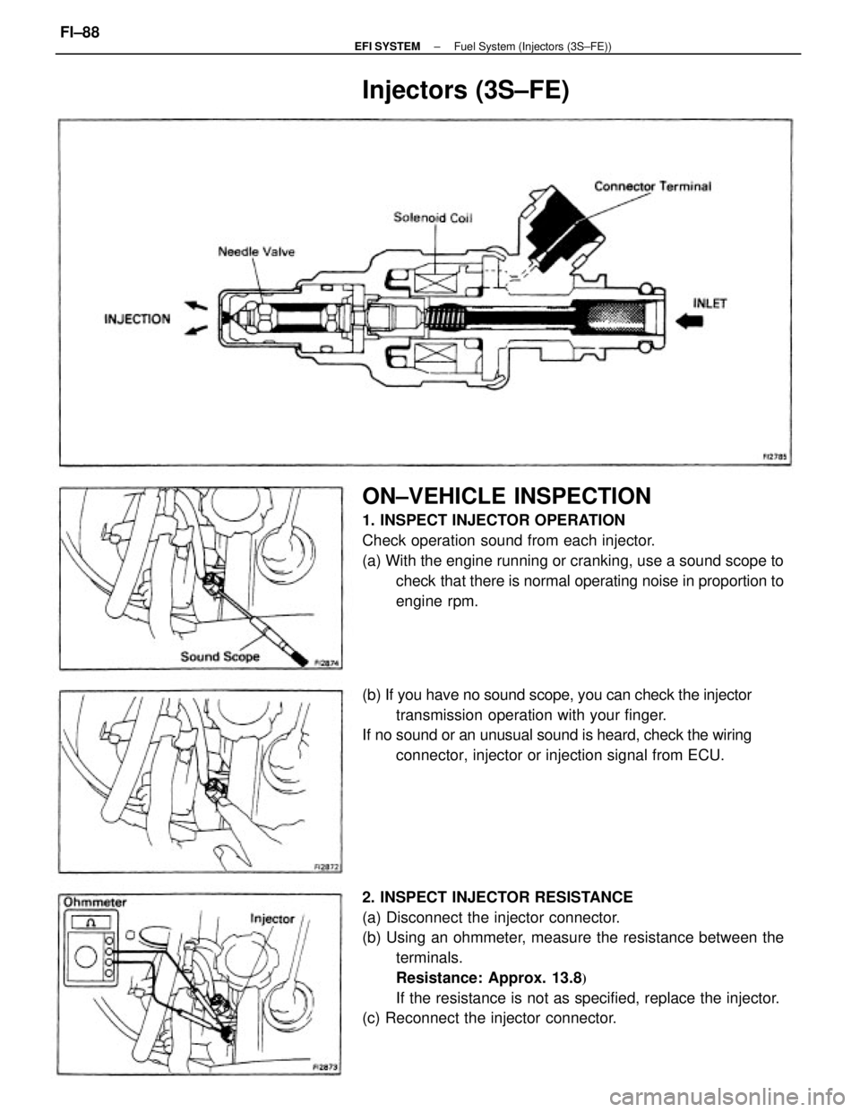
2. INSPECT INJECTOR RESISTANCE
(a) Disconnect the injector connector.
(b) Using an ohmmeter, measure the resistance between the
terminals.
Resistance: Approx. 13.8
�
If the resistance is not as specified, replace the injector.
(c) Reconnect the injector connector.
ON±VEHICLE INSPECTION
1. INSPECT INJECTOR OPERATION
Check operation sound from each injector.
(a) With the engine running or cranking, use a sound scope to
check that there is normal operating noise in proportion to
engine rpm.
(b) If you have no sound scope, you can check the injector
transmission operation with your finger.
If no sound or an unusual sound is heard, check the wiring
connector, injector or injection signal from ECU.
Injectors (3S±FE)
± EFI SYSTEMFuel System (Injectors (3S±FE))FI±88
Page 1104 of 2389
 Connect SST (wire) to the injector and battery for 15
seconds, and measure the injection volume with a gradu-
ated cylinder. Test each injector two or three times.
SST 09842±30070
Volume: 45 ±")
(k) Connect SST (wire) to the injector and battery for 15
seconds, and measure the injection volume with a gradu-
ated cylinder. Test each injector two or three times.
SST 09842±30070
Volume: 45 ± 55 cc (2.7 ± 3.4 cu in.) per 15 sec.
Difference between each injector:
5 cc (0.3 cu in.) or less
If the injection volume is not as specified, replace the injec-
tor.
2. INSPECT LEAKAGE.
(a) In the condition above, disconnect the. test probes of
SST (wire) from the battery and check the fuel leakage
from the injector.
SST 09842±30070
Fuel drop: One drop or less per minute
(b) Disconnect the battery negative (±) cable.
(c) Remove SST and the service wire.
SST 09268±4.1045 (e) Install a new O±ring to the injector.
(f) Connect SST (union and hose) to the injector, and hold
the injector and union with SST (clamp).
SST 09268±41045
(g) Put the injector into the graduated cylinder.
HINT: Install the a suitable vinyl hose onto the injector to
prevent gasoline from splashing out
(h) Reconnect the battery negative H cable.
(i) Turn the ignition switch ON.
HINT: Do not start the engine
(j) Using SST, connect terminals +B and FP of the check
connector.
SST 49843±18020 (e) Remove the pressure regulator. (See page FI±84)
(d) Connect the fuel return hose and SST (hose) to the
pressure regulator with SST (union), two new gaskets
and union bolt.
SST 09268±41045 (09268±41080, 09268±41090)
± EFI SYSTEMFuel System (Injectors (3S±FE))FI±90
Page 1107 of 2389
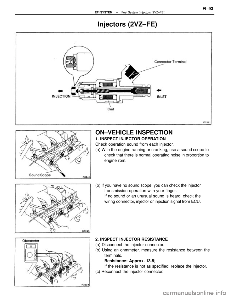
2. INSPECT INJECTOR RESISTANCE
(a) Disconnect the injector connector.
(b) Using an ohmmeter, measure the resistance between the
terminals.
Resistance: Approx. 13.8
�
If the resistance is not as specified, replace the injector.
(c) Reconnect the injector connector.
ON±VEHICLE INSPECTION
1. INSPECT INJECTOR OPERATION
Check operation sound from each injector.
(a) With the engine running or cranking, use a sound scope to
check that there is normal operating noise in proportion to
engine rpm.
(b) If you have no sound scope, you can check the injector
transmission operation with your finger.
If no sound or an unusual sound is heard, check the
wiring connector, injector or injection signal from ECU.
Injectors (2VZ±FE)
± EFI SYSTEMFuel System (Injectors (2VZ±FE))FI±93
Page 1108 of 2389

3. (A/T)
DISCONNECT THROTTLE CABLE FROM THROTTLE
BODY AND BRACKET
4. DISCONNECT ACCE")
REMOVAL OF INJECTORS
1. DISCONNECT CABLE FROM NEGATIVE TERMINAL
OF BATTERY
2. DRAIN ENGINE COOLANT (See page CO±5)
3. (A/T)
DISCONNECT THROTTLE CABLE FROM THROTTLE
BODY AND BRACKET
4. DISCONNECT ACCELERATOR CABLE AND BRACKET
FROM THROTTLE BODY AND AIR INTAKE CHAMBER
5. REMOVE AIR CLEANER CAP, AIR FLOW METER AND
AIR CLEANER HOSE
(a) Disconnect the. air flow meter connector.
(b) Disconnect the air hoses.
(e) Loosen the air cleaner hose clamp bolt.
(d) Disconnect the air cleaner cap clips.
(e) Remove the air cleaner cap and air flow meter
together with the air cleaner hose.
6. DISCONNECT HOSES AND CONNECTORS
(a) PCV hoses
(b) Vacuum sensing hose
(e) Water by±pass hoses
(d) Fuel pressure control VSV hose
(e) Emission control vacuum hoses
(f) ISC connector
(g) Throttle position sensor connector
(h) (CALIF. only)
EGR gas temp. sensor connector
7. REMOVE NO. 1 RH ENGINE MOUNTING STAY
Remove the three bolts and mounting stay.
8. DISCONNECT COLD START INJECTOR CONNECTOR
9. DISCONNECT COLD START INJECTOR TUBE
(See step 3 on page FI±81 )
± EFI SYSTEMFuel System (Injectors (2VZ±FE))FI±94
Page 1109 of 2389
 Brake booster vacuum hose
(b) PS vacuum and air hoses
(c) Cruise control vacuum hose
(d) Ground strap connector
(e) Wire harness clamp
Remove the nut, and disconnect")
10. DISCONNECT HOSES AND PARTS
(a) Brake booster vacuum hose
(b) PS vacuum and air hoses
(c) Cruise control vacuum hose
(d) Ground strap connector
(e) Wire harness clamp
Remove the nut, and disconnect the wire harness clamp.
(f) Fuel pressure control VSV hose.
11. DISCONNECT WIRE HARNESS CLAMP
Remove the nut and disconnect the wire harness.
12. DISCONNECT EGR PIPE
13. REMOVE NO.1 ENGINE HANGER AND AIR INTAKE
CHAMBER STAY
(a) Remove the two bolts and No.1 engine hanger.
(b) Remove the bolt, and disconnect the air intake chamber
stay from air intake chamber.
14. REMOVE AIR INTAKE CHAMBER
Remove the two bolts, nuts, air intake chamber and gasket.
15. DISCONNECT CONNECTORS
(a) Cold start injector connector
(b) Water temperature sensor connector
(c) Six injector connectors
16. DISCONNECT WIRE HARNESS CLAMPS FROM LH
DELIVERY PIPE
Disconnect the three wire harness clamp.
17. DISCONNECT FUEL INLET AND TWO RETURN
HOSES
(a) Disconnect the fuel return hoses from the fuel pressure reg-
ulator and No.1 fuel pipe.
(b) Disconnect the fuel inlet hose from the fuel filter.
18. REMOVE NO.2 FUEL PIPE
Remove the two union bolts, four gaskets and No.2 fuel
pipe.
± EFI SYSTEMFuel System (Injectors (2VZ±FE))FI±95

Check wiring between ECU terminal E 1 and body
ground.
Check GAUGE fu")