Page 1311 of 2389

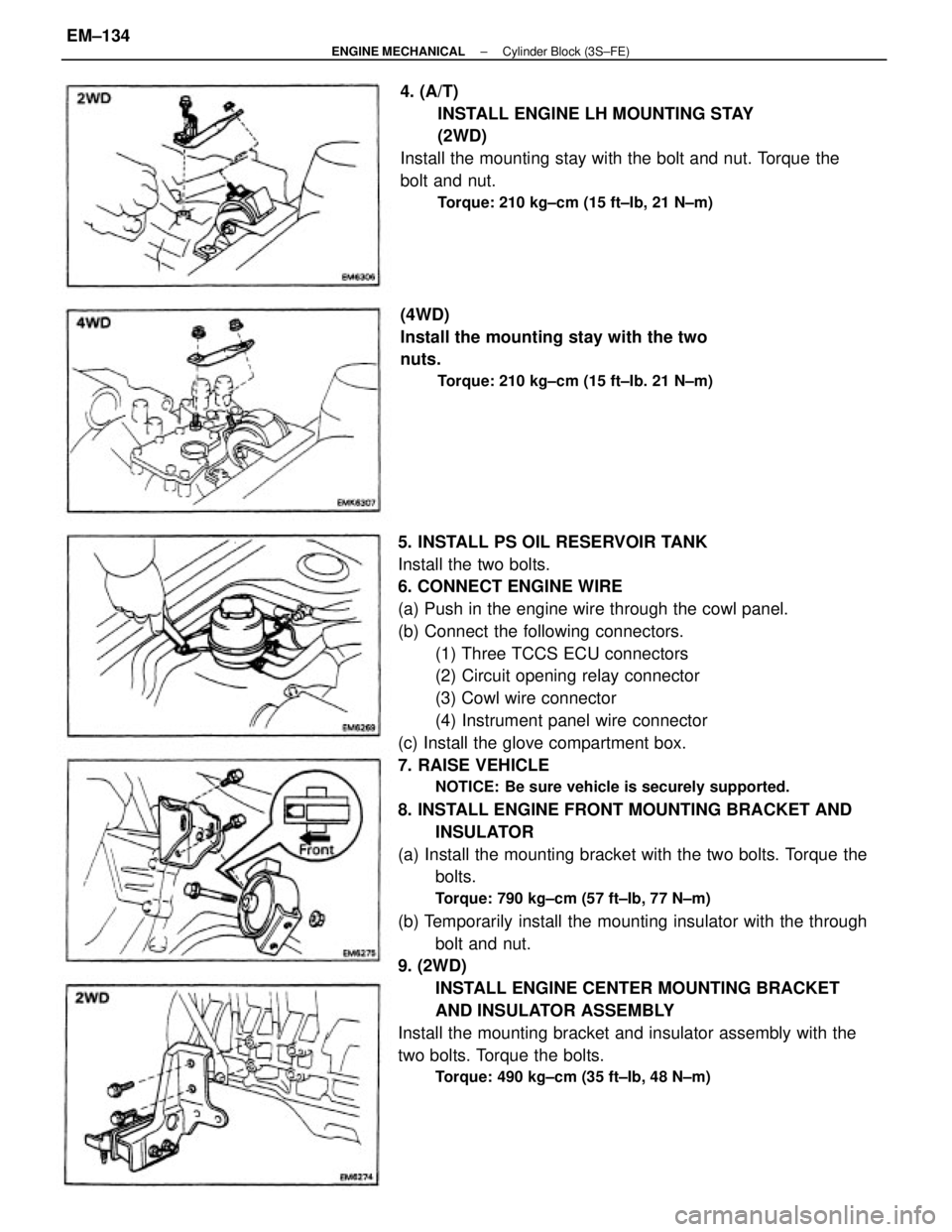
5. INSTALL PS OIL RESERVOIR TANK
Install the two bolts.
6. CONNECT ENGINE WIRE
(a) Push in the engine wire through the cowl panel.
(b) Connect the following connectors.
(1) Three TCCS ECU connectors
(2) Circuit opening relay connector
(3) Cowl wire connector
(4) Instrument panel wire connector
(c) Install the glove compartment box.
7. RAISE VEHICLE
NOTICE: Be sure vehicle is securely supported.
8. INSTALL ENGINE FRONT MOUNTING BRACKET AND
INSULATOR
(a) Install the mounting bracket with the two bolts. Torque the
bolts.
Torque: 790 kg±cm (57 ft±Ib, 77 N±m)
(b) Temporarily install the mounting insulator with the through
bolt and nut.
9. (2WD)
INSTALL ENGINE CENTER MOUNTING BRACKET
AND INSULATOR ASSEMBLY
Install the mounting bracket and insulator assembly with the
two bolts. Torque the bolts.
Torque: 490 kg±cm (35 ft±Ib, 48 N±m)
4. (A/T)
INSTALL ENGINE LH MOUNTING STAY
(2WD)
Install the mounting stay with the bolt and nut. Torque the
bolt and nut.
Torque: 210 kg±cm (15 ft±Ib, 21 N±m)
(4WD)
Install the mounting stay with the two
nuts.
Torque: 210 kg±cm (15 ft±Ib. 21 N±m)
± ENGINE MECHANICALCylinder Block (3S±FE)EM±134
Page 1319 of 2389

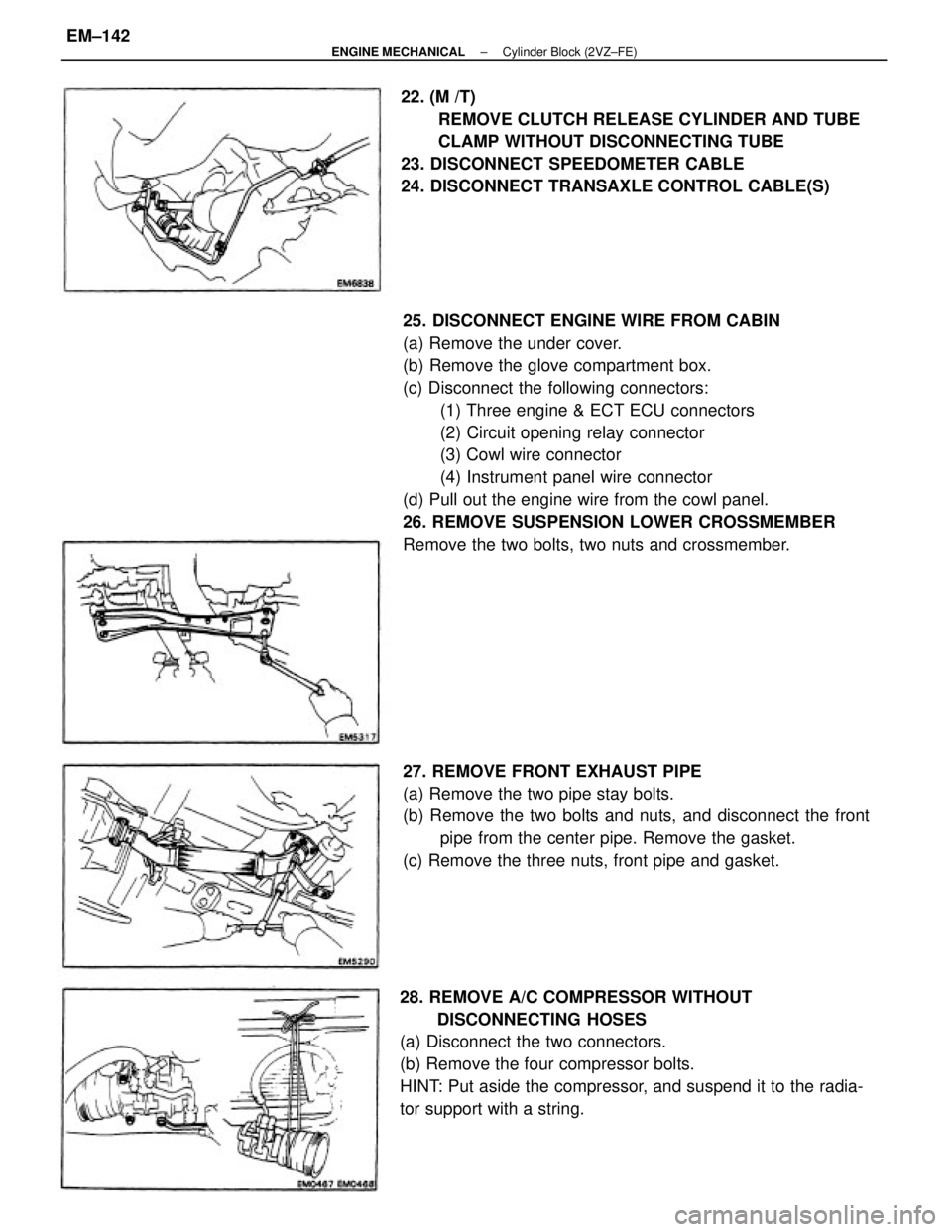
25. DISCONNECT ENGINE WIRE FROM CABIN
(a) Remove the under cover.
(b) Remove the glove compartment box.
(c) Disconnect the following connectors:
(1) Three engine & ECT ECU connectors
(2) Circuit opening relay connector
(3) Cowl wire connector
(4) Instrument panel wire connector
(d) Pull out the engine wire from the cowl panel.
26. REMOVE SUSPENSION LOWER CROSSMEMBER
Remove the two bolts, two nuts and crossmember.
28. REMOVE A/C COMPRESSOR WITHOUT
DISCONNECTING HOSES
(a) Disconnect the two connectors.
(b) Remove the four compressor bolts.
HINT: Put aside the compressor, and suspend it to the radia-
tor support with a string.22. (M /T)
REMOVE CLUTCH RELEASE CYLINDER AND TUBE
CLAMP WITHOUT DISCONNECTING TUBE
23. DISCONNECT SPEEDOMETER CABLE
24. DISCONNECT TRANSAXLE CONTROL CABLE(S)
27. REMOVE FRONT EXHAUST PIPE
(a) Remove the two pipe stay bolts.
(b) Remove the two bolts and nuts, and disconnect the front
pipe from the center pipe. Remove the gasket.
(c) Remove the three nuts, front pipe and gasket.
± ENGINE MECHANICALCylinder Block (2VZ±FE)EM±142
Page 1349 of 2389

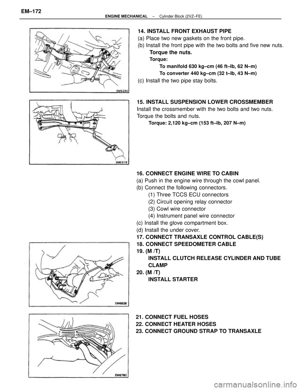
16. CONNECT ENGINE WIRE TO CABIN
(a) Push in the engine wire through the cowl panel.
(b) Connect the following connectors.
(1) Three TCCS ECU connectors
(2) Circuit opening relay connector
(3) Cowl wire connector
(4) Instrument panel wire connector
(c) Install the glove compartment box.
(d) Install the under cover.
17. CONNECT TRANSAXLE CONTROL CABLE(S)
18. CONNECT SPEEDOMETER CABLE
19. (M /T)
INSTALL CLUTCH RELEASE CYLINDER AND TUBE
CLAMP
20. (M /T)
INSTALL STARTER 14. INSTALL FRONT EXHAUST PIPE
(a) Place two new gaskets on the front pipe.
(b) Install the front pipe with the two bolts and five new nuts.
Torque the nuts.
Torque:
To manifold 630 kg±cm (46 ft±Ib, 62 N±m)
To converter 440 kg±cm (32 t±Ib, 43 N±m)
(c) Install the two pipe stay bolts.
15. INSTALL SUSPENSION LOWER CROSSMEMBER
Install the crossmember with the two bolts and two nuts.
Torque the bolts and nuts.
Torque: 2,120 kg±cm (153 ft±lb, 207 N±m)
21. CONNECT FUEL HOSES
22. CONNECT HEATER HOSES
23. CONNECT GROUND STRAP TO TRANSAXLE
± ENGINE MECHANICALCylinder Block (2VZ±FE)EM±172