1986 CHEVROLET CORVAIR check engine light
[x] Cancel search: check engine lightPage 5 of 56
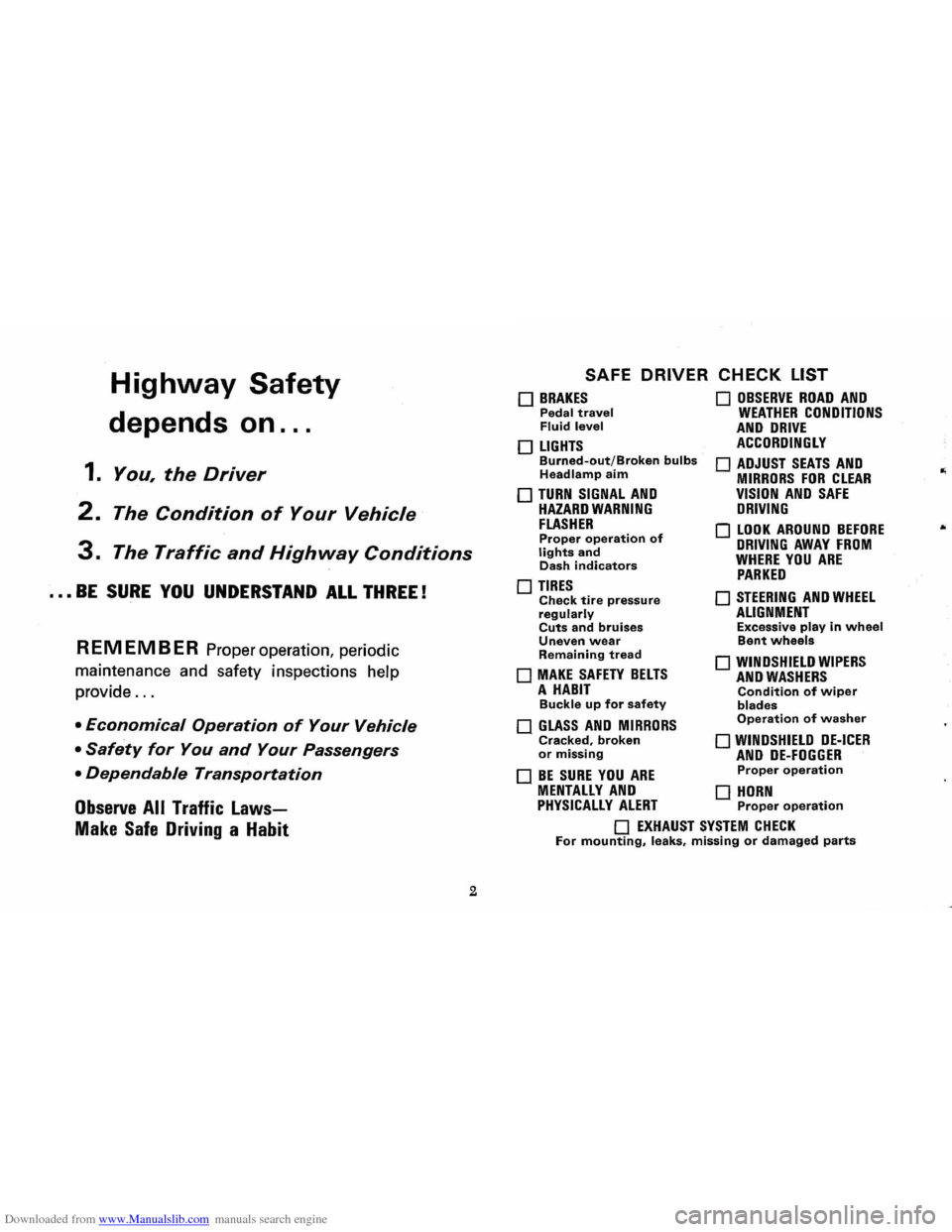
Downloaded from www.Manualslib.com manuals search engine Highway Safety
depends on ...
1. You, the Driver
2. The Condition of Your Vehicle
3. The Traffic and Highway Conditions
••• BE SURE YOU UNDERSTAND ALL THREE!
REMEMBER Proper operation, periodic
maintenance and safety inspections help
provide
...
• Economical Operation of Your Vehicle
• Safety for You and Your Passengers
• Dependable Transportation
Observe All Traffic Laws
Make Safe Driving a Habit
2
SAFE DRIVER CHECK LIST
o BRAKES Pedal travel Fluid level
o LIGHTS Burned-out/Broken bulbs Headlamp aim
o TURN SIGNAL AND HAZARD WARNING FLASHER Proper operation of lights and Dash indicators
o TIRES Check tire pressure regularly Cuts and bruises Uneven wear Remaining tread
o MAKE SAFETY BELTS A HABIT Buckle up for safety
o GLASS AND MIRRORS Cracked, broken or missing
o BE SURE YOU ARE
o OBSERVE ROAD AND WEATHER CONDITIONS AND DRIVE ACCORDINGLY
o ADJUST SEATS AND MIRRORS FOR CLEAR VISION AND SAFE DRIVING
o LOOK AROUND BEFORE DRIVING AWAY FROM WHERE YOU ARE PARKED
o STEERING AND WHEEL ALIGNMENT Excessive play in wheel Bent wheels
o WINDSHIELD WIPERS AND WASHERS Condition of wiper blades Operation of washer
o WINDSHIELD DE-ICER AND DE-FOGGER Proper operation
MENTALLY AND 0 HORN PHYSICALLY ALERT Proper operation
o EXHAUST SYSTEM CHECK For mounting, leaks, missing or damaged parts
Page 16 of 56
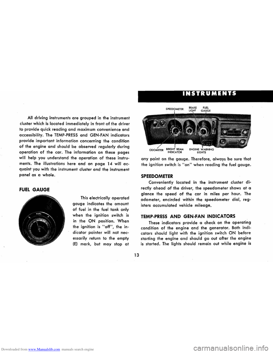
Downloaded from www.Manualslib.com manuals search engine All driving instruments are grouped in the instrument
cluster which
is located immediately in front of the driver
to provide quick
reading and maximum convenience and
accessibility. The TEMP-PRESS and GEN-FAN indicators
provide important information concerning the condition
of the engine and should be observed regularly during
operation of the car. The information on these pages
will help you understand the operation of these instru
ments . The illustrations
here and on page 14 will ac
quaint you with the instrument cluster and the instrument
panel as a whole.
FUEL GAUGE
This electrically operated
gauge indicates the amount
of fuel in the fuel tank only
when the ignition switch is
in the ON position. When
the ignition is "off", the in
dicator pointer
will not nec
essarily return to the empty
IE) mark, but may stop at
I
13
INSTRUMENTS
any point on the gauge. Therefore, always be sure that
the ignition switch is "on" when reading the fuel gauge.
SPEEDOMETER
Conveniently located in the instrument cluster di
rectly ahead of the driver, the speedometer shows at a
glance the speed of the car in miles per hour. The
odometer, encircled within the speedometer dial, reg
isters accumulated vehicle
mileage.
TEMP-PRESS AND GEN-FAN INDICATORS
These indicators provide a check on the operating
condition of the engine and the generator. Both indi
cators
should light with the ignition switch ON before
starting the engine and should go out after the engine
is started. The lights should remain out while engine is
Page 17 of 56
Downloaded from www.Manualslib.com manuals search engine operating, except the GEN-FAN indicator rna)' flicker
when
engine is idling.
CAUTION: If either of these indicators light
while .
car is being. -driYen, immediately follow the
procedure outlined .vnder "EMERGENCY OPER
ATING INSTRUCTIONS," so car may be driyen
to the nearest service facility.
BRAKE SYSTEM WARNING LIGHT
This dual purpose indicator light operates as
follows:
With parking brake applied the red light will light
when
the ignition switch is turned on.
As a dual service brake system warning, the red
light will come on when the brake pedal is depressed
if low pressure has developed in either the front or
rear brake system. Have your authorized Chevrolet
dealer locate and correct the trouble immediately.
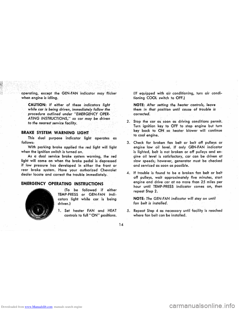
EMERGENCY OPERATING INSTRUCTIONS
(To be followed if either
TEMP-PRESS or GEN-FAN indi
cators
light while car is being
driven.)
1. Set heoter FAN and HEAT
controls to full "ON" positions.
14
(If equipped with air conditioning, turn air condi
tioning
COOL switch to OFF.)
NOTE: After setting the heater controls, leave
them in that position until cause of trouble is
corrected.
2.
Stop the car a -s , soon as driving conditions permit.
furn ignition
key to OFF to stop engine but turn
key
back to·-PNso heoter blower will continue
to
cool engine.
3. Check for broken fan belt or belt off pulleys or
engine low oil level. If only GEN-FAN indicator
is lighted, belt is not broken or off pulleys and en
gine oil level is satisfactory, car can be driven at
slow speeds; however, generator must be checked
and serviced as soon as possible.
4. If trouble is found to be a broken fan belt or belt
off pulleys, wait approximately five minutes, start
engine and drive car at no more than 25 miles per
hour until TEMP-PRESS indicator comes on, then
repeat Step 2.
NOTE: The GEN-FAN indicator will stay on until
fan
belt is installed.
5. Repeat Step 4 as necessary until facility is reached
where fan belt can be installed.
Page 18 of 56
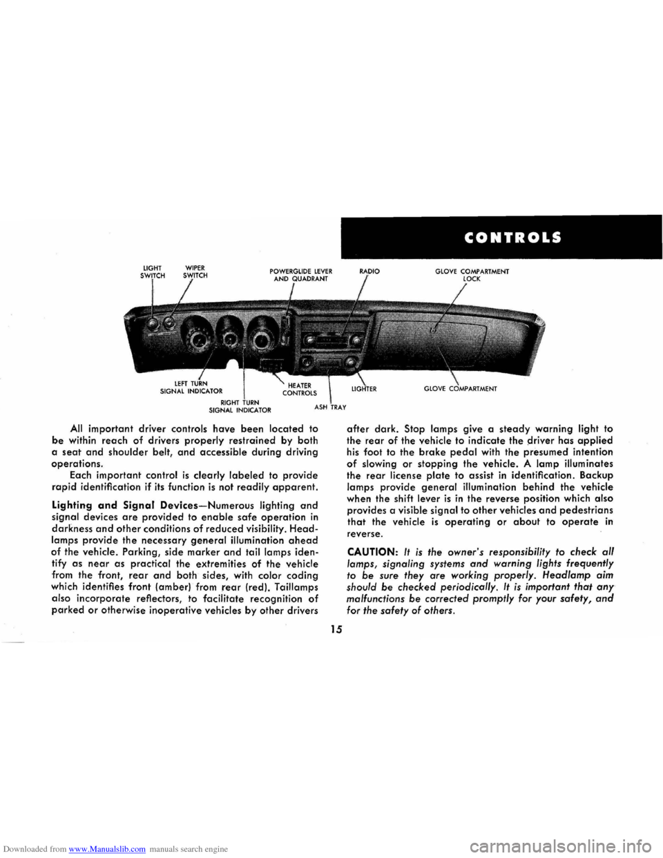
Downloaded from www.Manualslib.com manuals search engine All important driver controls have been located to
be within reach of drivers properly restrained by both
a
seat and shoulder belt, and accessible during driving
operations.
Each important
control is clearly labeled to provide
rapid identification if its function is not readily apparent.
Lighting and Signal Devices-Numerous lighting and
signal devices are provided to enable safe operation in
darkness and other conditions of reduced visibility. Head
lamps provide the necessary general illumination ahead
of the vehicle. Parking, side marker and tail lamps iden
tify
as near as practical the extremities of the vehicle
from the front,
rear and both sides, with color coding
which identifies front (amber) from rear (red). Taillamps
also
incorporate reflectors, to facilitate recognition of
parked or otherwise inoperative vehicles by other drivers
15
CONTROLS
GLOVE COMPARTMENT
after dark. Stop lamps give a steady warning light to
the rear of the vehicle to indicate the ~river has applied
his foot to the brake pedal with the presumed intention
of slowing or stopping the vehicle. A lamp illuminates
the rear license plate to assist in identification. Backup
lamps provide general illumination behind the vehicle
when the shift
lever is in the reverse position which also
provides a visible signal to other vehicles and pedestrians
that the vehicle is operating or about to operate in
reverse.
CAUTION: It is the owner's responsibility to check al/
lamps, signaling systems and warning lights frequently
to be sure they are working properly. Head/amp aim
should
be checked periodicol/y. It is important that any
malfunctions be corrected promptly for your safety, and
for the safety of others.
Page 19 of 56
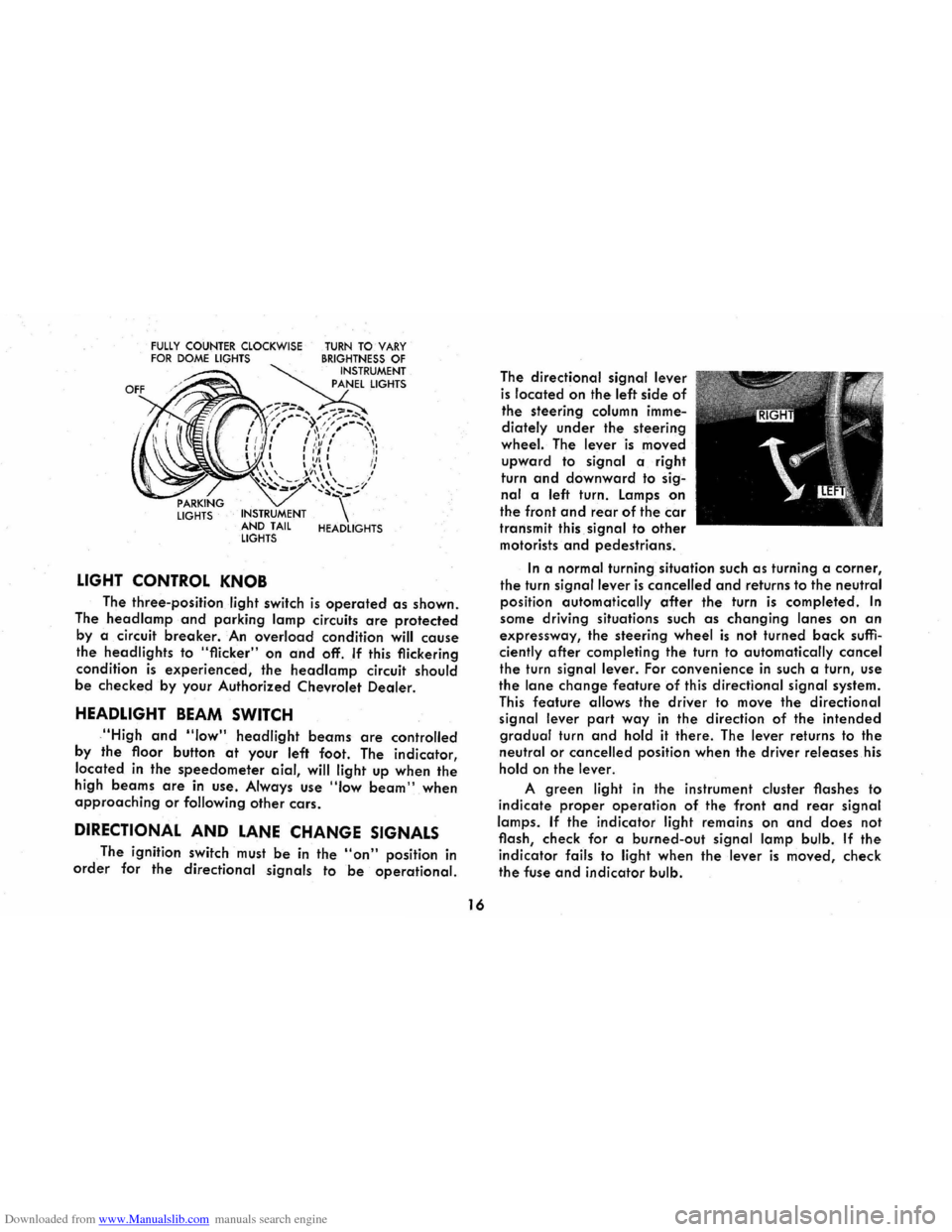
Downloaded from www.Manualslib.com manuals search engine FULLY COUNTER CLOCKWISE FOR DOME LIGHTS
LIGHTS INSTRUMENT
AND TAIL
LIGHTS
LIGHT CONTROL KNOB
TURN TO VARY BRIGHTNESS OF INSTRUMENT
PANEL LIGHTS
HEADLIGHTS
The three-position light switch is operated as shown.
The
head lamp and parking lamp circuits are protected
by a circuit breaker. An overload condition will cause
the headlights to "flicker" on and off. If this flickering
condition
is experienced, the headlamp circuit should
be checked by your Authorized Chevrolet Dealer.
HEADLIGHT BEAM SWITCH
,"High and "low" headlight beams are controlled
by
the floor button at your left foot. The indicator,
located
in the speedometer aial, will light up when the
high beams are in use . Always use "Iow beam" when approaching or following other cars.
DIRECTIONAL AND LANE CHANGE SIGNALS
The ignition switch must be in the "on" position in
order for the directional signals to be operational.
16
The directional signal lever
is located on the left side of
the steering column imme
diately
under the steering
wheel. The lever is moved
upward to signal a right
turn
and downward to sig
nal a left turn. Lamps on
the front and rear of the car
transmit this signal to other
motorists and pedestrians.
In a normal turning situation such as turning a corner,
the turn signal lever is cancelled and returns to the neutral
position automatically
after the turn is completed. In
some driving situations such as changing lanes on an
expressway, the steering wheel is not turned back suffi
ciently after completing the turn to automatically cancel
the turn signal lever. For convenience in such a turn, use
the lane change feature of this directional signal system.
This feature allows the driver to move the directional
signal lever
part way in the direction of the intended
gradual turn and hold it there. The lever returns to the
neutral or cancelled position when the driver releases his
hold on the lever.
A green light in the instrument cluster flashes to
indicate
proper operation of the front and rear signal
lamps.
If the indicator light remains on and does not
flash, check for a burned-out
signal lamp bulb. If the
indicator fails to light when the lever is moved, check
the fuse and indicator bulb.
Page 20 of 56
Downloaded from www.Manualslib.com manuals search engine If the system is not functioning properly, a legal hand
signal should be given, since failure to indicate a turn
is considered a moving traffic violation in many states.
Always signal for a turn
at a reasonable distance before actu 'ally making it.
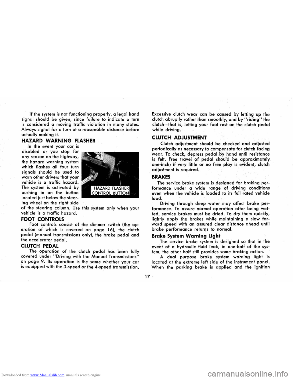
HAZARD WARNING FLASHER
In the event your car is
disabled or you stop for
any reason on the highway,
the
hazard warning system
which flashes all four turn
signals should
be used to
warn
other drivers that your
vehicle
is a traffic hazard.
The system is activated by
pushing
in on the button
located just
below the steer
ing wheel on the right side
of the steering column. Use this system only when your
vehicle
is a traffic hazard.
FOOT CONTROLS Foot controls consist of the dimmer switch (the op
eration of which is covered on page 16), the clutch
pedal (manual transmissions only), the brake pedal and
the accelerator pedal.
CLUTCH PEDAL The operation of the clutch pedal has been fully
covered under
"Driving with the Manual Transmissions"
on
page 9. Its operation is the same whether your car
is equipped with the 3-speed or the 4-speed transmission. Excessive
clutch
wear can be caused by letting up the
clutch abruptly
rather than smoothly, and by "riding" the
clutch-that is, letting your foot rest on the clutch pedal
while driving .
CLUTCH ADJUSTMENT
Clutch adjustment should be checked and adjusted
periodically as necessary to compensate for clutch facing
wear. To check, depress pedal.by hand until resistance
is felt. Free travel of pedal should be approximately
one-inch;
if very little or no free play is evident, clutch
adjustment
is required.
BRAKES
The service brake system is designed for braking per
formance under a wide range of driving conditions
even when the vehicle
is loaded to its full rated vehicle
load. Driving through deep water may affect brake per
formance. To assure normal operation after being wet
ted, service brakes must be dried. To dry them quickly,
lightly
apply the brakes while maintaining a slow for"
ward speed with an assured clear distance ahead until
brake performance re'turns to normal.
Brake System Warning Light
The service brake system is designed so that in the
event of a hydraulic fluid leak,
in one-half of the sys
tem, the other half still provides some braking action.
A dual purpose brake system warning light is
located at the extreme left side of the instrument panel.
When the parking brake is applied and the ignition
17 .
Page 50 of 56
Downloaded from www.Manualslib.com manuals search engine MINOR TROUBLE SHOOTING PROCEDURES
The chart on the previous page, and the information on the pages
which follow, contains information designed to aid the average
driver to discover, and possibly correct, conditions resulting in minor
mechanical
difficulties in his car. The chart, designed to point out
possible solutions to
several of the most common automotive mal
functions
and point out a logical checking sequence, will lead step
by step to the most likely causes and corrective procedures. If, after
making the checks and adjustments suggested, the source of the
trouble
has not been found and corrected, it is strongly recom
mended
that an Authorized Chevrolet Dealer inspect the vehicle and
make whatever repairs or adjustments are necessary.
FUEL SYSTEM AND ENGINE
If the ignition switch will cause the engine to "turn over" or
"crank" but the car will not start, check Steps A through D below.
NOTE:
If continual "flooding" of the carburetor is evidenced by a
carburetor wet with fuel or black exhaust smoke, perform the
operation
suggested in paragraph 0 only .
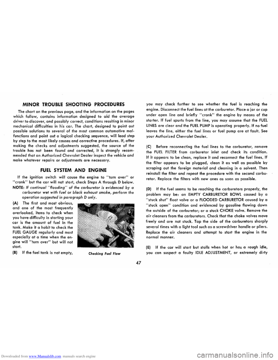
(A) The first and most obvious,
and one of the most frequently
overlooked, items to check when
you
have- difficulty in starting your
car is the amount of fuel in the
tank.
Make it a habit to check the
FUEL GAUGE regularly and most
especially
at a time when the en
gine will "turn over" but will not
start.
(8)
If the fuel tank is not empty, Checking Fuel Flow
47
you may check further to see whether the fuel is reaching the
engine. Disconnect the fuel lines
at the carburetor. Place a jar or cup
under open line and briefly "crank" the engine by means of the
starter. If fuel spurts from the line, you may assume that the FUEL
LINES are clear and the FUEL PUMP is operating properly. If no fuel
leaves the line, either the fuel lines
or fuel pump are at fault. See
your Authorized Chevrolet Dealer.
(C) Before reconnecting the fuel lines to the carburetor, remove
the
FUel FilTER from carburetor inlet and check its condition.
If it appears to be clean, replace it and reconnect the fuel lines. If
the filter appears to be plugged, clean it as well as possible by
scraping out the foreign material and cleaning in a solvent. Then
reinstall the filter
and repeat the procedure with the second carbu
retor. Replace the filters with new ones as soon as possible .
(0) If the fuel seems to be reaching the carburetors properly, the
problem may
be: an EMPTY CARBURETOR BOWL caused by a
"stuck shut" float valve or a flOODED CARBURETOR caused by a
"stuck open" condition and evidenced by gasoline flowing down
the outside
of the carburetor; or a stuck CHOKE valve. Remove the
air cleaners from the carburetors. Check that the choke valves move
freely and are not stuck. Tap the side of the carburetors sharply
several times with a light tool such as a screwdriver handle or pliers.
Replace the
air deaners and attempt to start the engine in the
normal manner.
(E) If the car will start but stalls when hot or has a rough idle,
you
can suspect a faulty IDLE ADJUSTMENT, or extremely dirty
Page 51 of 56
Downloaded from www.Manualslib.com manuals search engine and blocked AIR CLEANER ELEMENTS. Replace the air cleaner ele
ments
if necessary. Idle adjustment should be performed by your
Chevrolet Dealer.
If the above Fuel System checks and the checks suggested under
the Electrical System following do not correct the malfunction, it is
recommended that you turn to your Authorized Chevrolet Dealer
for further checks, adjustments
or repairs.
ELECTRICAL SYSTEM
If, when the ignition key is turned to START, the engine will not
turn over, you have
good reason to suspect electrical trouble.
(F) When there is no response at all to attempts to start the car,
check the obvious-your AUTOMATIC TRANSMISSION SELECTOR
LEVER must be in neutral position before the engine can be started.
Turning the IGNITION SWITCH rapidly back and forth several
times
will sometimes correct a poor internal switch contact.
(G) The BATTERY may be discharged. If so, lights will be dim and
the horn will have a poor tone if it will blow at all.
Usually
a garage recharge will be necessary to return the battery
to operotion. Occasionally, however, a long drive will recharge
the battery.
NOTE:
If the battery is determined to be dead, and for no apparent
reason, have
your Authorized Chevrolet Dealer check the
battery, the GENERATOR and the
VOLTAGE REGULATOR.
GENERATOR trouble should already have been indicated
by
the indicator on the instrument panel. Never remove generator
"BAT" lead without first disconnecting battery ground cable.
48
POOR BATTERY CONNECTIONS may be suspected if the car has operated properly a short time before and now not even the horn
will operate. Check both ends of both battery cables. If the con
nections are corroded, a car may sometimes be restored to operation by removing all cable ends, scraping all contacting surfaces
clean with a pen knife, and reassembling. If the cables are broken,
they must be replaced. The power supply should now be restored
unless the battery is dead.
(H) If, however, the lights and horn work properly but the starter will still not turn over, check the STARTER connections. A "click" from the starter solenoid indicates that the wiring to the starter is properly installed. If the wiring seems to be clean and tightly installed, the trouble is probably in the starter itself and should be referred to your Authorized Chevrolet Dealer.
When the engine will "turn over" but will not start, the following
items may be checked along with Fuel System Checks listed previously.
(I) With a clean dry cloth wipe the ceramic portions of the spark plugs dry. In particularly damp or rainy weather dampness may be the cause of not sta rting, especially when the engine is cold.
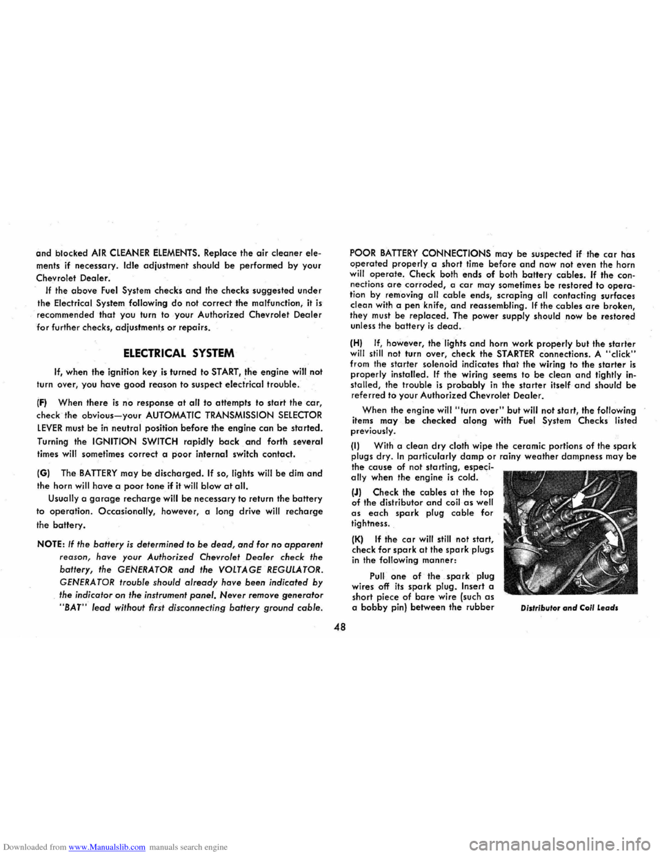
(J) Check the cables at the top of the distributor and coil as well as each spark plug cable for
tightness.
(K) If the car will still not start, check for spark at the spark plugs in the following manner:
Pull one of the spark plug
wires off its spark plug. Insert a
short piece of bare wire (such as a bobby pin) between the rubber Distributor and Coil Leads