Page 477 of 885
PROPELLER SHAFT - Propeller ShaftPR.3
REMOVAL AND DISASSEMBLY OF
PROPELLER SHAFT
(See page PR-21
1. DISCONNECT PROPELLER SHAFT FLANGE FROM
COMPANION FLANGE ON DIFFERENTIAL
(a) Place matchmarks on the flanges.
(b) Remove the four bolts and nuts.
2. REMOVE TWO BOLTS HOLDING CENTER SUPPORT
BEARING TO BODY
3. REMOVE PROPELLER SHAFT WITH INTERMEDIATE
SHAFT
h) Pull out the yoke from the transmission.
(b) Insert SST in the transmission to prevent oil leakage.
ssT 09325-1 20rO
4. SEPARATE PROPELLER SHAFT AND INTERMEDIATE
SHAFT
(a) Place matchmarks on the flanges.
(b) Remove the four bolts and nuts.
5. REMOVE CENTER SUPPORT BEARING FROM
INTERMEDIATE SHAFT
(a) Using a hammer and chisel, loosen the staked part of
the nut.
(b) Using SST to hold the flange, remove the nut.
ssT 09330-00020
Page 489 of 885
FRONT AXLE AND SUSPENSION - Axle Hub
8. REMOVE AXLE HUB FROM
Using SST, remove the axle hub.
ssT 09950-2001 5
,. CAUTION: Cover the drive shaftrhl
( protect it from damage. (r':q
;; , +in f,rlve tl""ff\ii
!,ocr* d i t{" cIo*h to " .rr:'r,
g ra *e c* i t € ro*r ata ^4 1e.
REPLACEMENT OF FRONT AXLE HUB AND
WHEEL BEARING
(See page FA-7)
1. REMOVE DUST DEFLECTOR
Using a screwdriver, remove the dust deflector.
REMOVE INNER OIL SEAL FROM STEERING
KNUCKLE
Using SST, pull ou.t the oil seal.
ssr 09308-0001 0
REMOVE HOLE SNAP RING
Using snap ring pliers, remove the hole snap ring.
REMOVE THREE BOLTS
Remove the three bolts holding the disc brake dust
to the steering knuckle.
,..F. REMOVE AXLE HUQ FROM STEERING KNUCKLE€r:
Using SST, push off the axle hub.
ssT 09950-2001 5
6. REMOVE DISC BRAKE DUST COVER
7. REMOVE BEARING INNER RACE'(INSIDE)
2.
a
,{n.1n
t
3.
4.
fr
,f+
8. REMOVE. BEARTNG rlruen.qAbe (OUrSlOe)
Using 9ST, pull off the beaiing'inner race.
ssT 09950;20015 t r
Page 490 of 885

FA.1O
' -'v7:'
FRONT AXLE AND SUSPENSION - Axle Hub
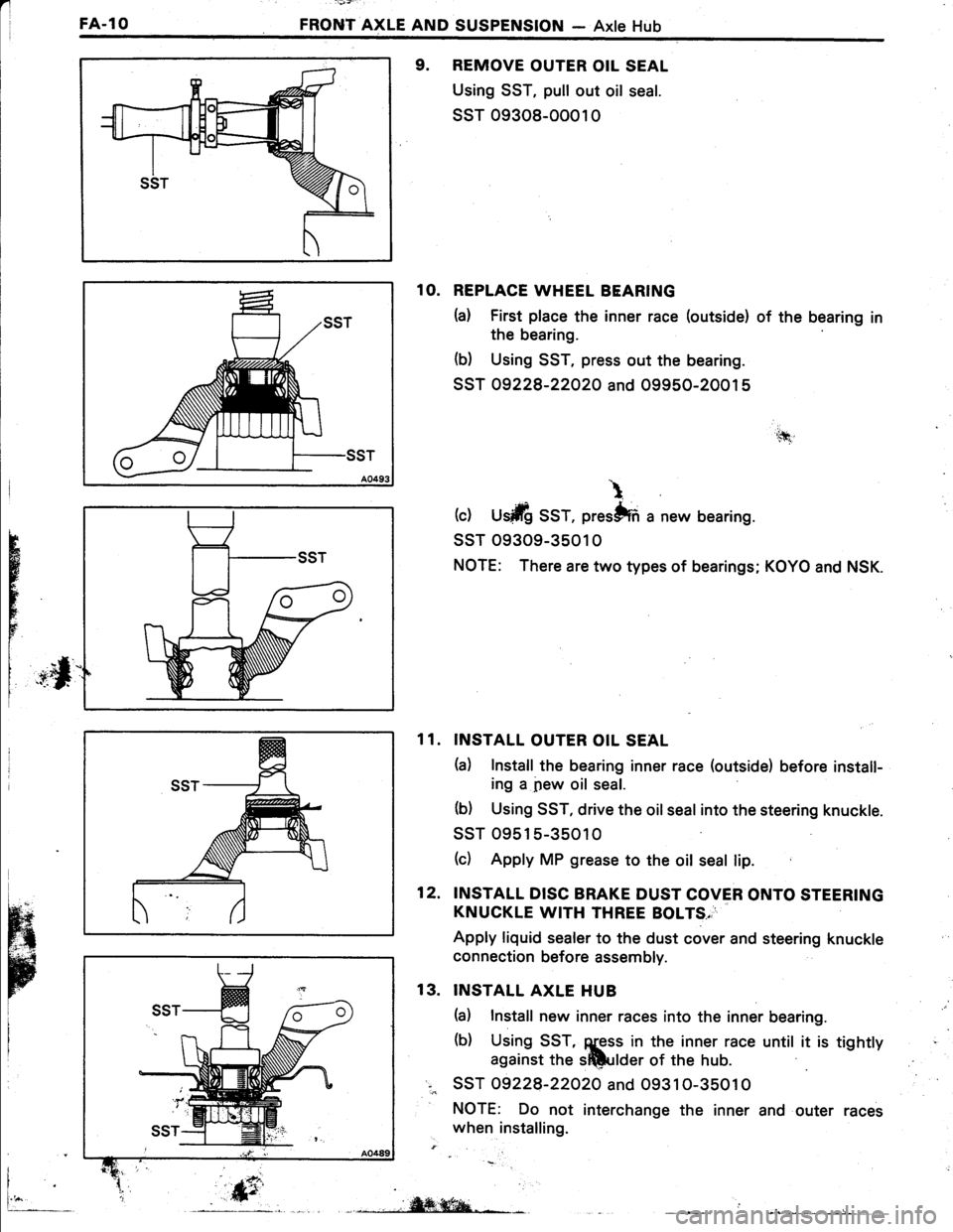
9. REMOVE OUTER OIL SEAL
Using SST, pull out oil seal.
ssT 09308-0001 0
1O. REPLACE WHEEL BEARING
h) First place the inner race (outside) of the bearing in
the bearing
(b) Using SST, press out the bearing.
SST 09228-22O2O and 09950-20015
(c) U$ilfi SST, prestffi a new bearing.
ssT 09309-3501 0
NOTE: There are two types of bearings; KOYO and NSK.
INSTALL OUTER OIL SEAL
h) Install the bearing inner race (outside) before install-
ing a pew oil seal.
(b) Using SST, drive the oil seal into the steering knuckle.
ssT 09515-35010
(c) Apply MP grease to the oit seal lip.
INSTALL DISC BRAKE DUST COVER ONTO STEERING
KNUCKLE WITH THREE BOLTS,
Apply liquid sealer to the dust cover and steering knuckle
connection before assembly.
INSTALL AXLE HUB
(a) Install new inner races into the inner bearing.
(b) Using SST, ggss in the inner race until it is tightty
against the sftlulder of the hub.
SST 09228-22O2O and O9310-35010
NOTE: Do not interchange the inner and outer races
when installing.
'.tfi
\
H
r
FE
11.
12.
13.
i
fr_, .,,iW;ffiqa-*L- L __
Page 491 of 885

_ l +l i'-:r': : '
FRONT AXLE AND SUSPENSION - Axle HubFA-l1
3.3 -+
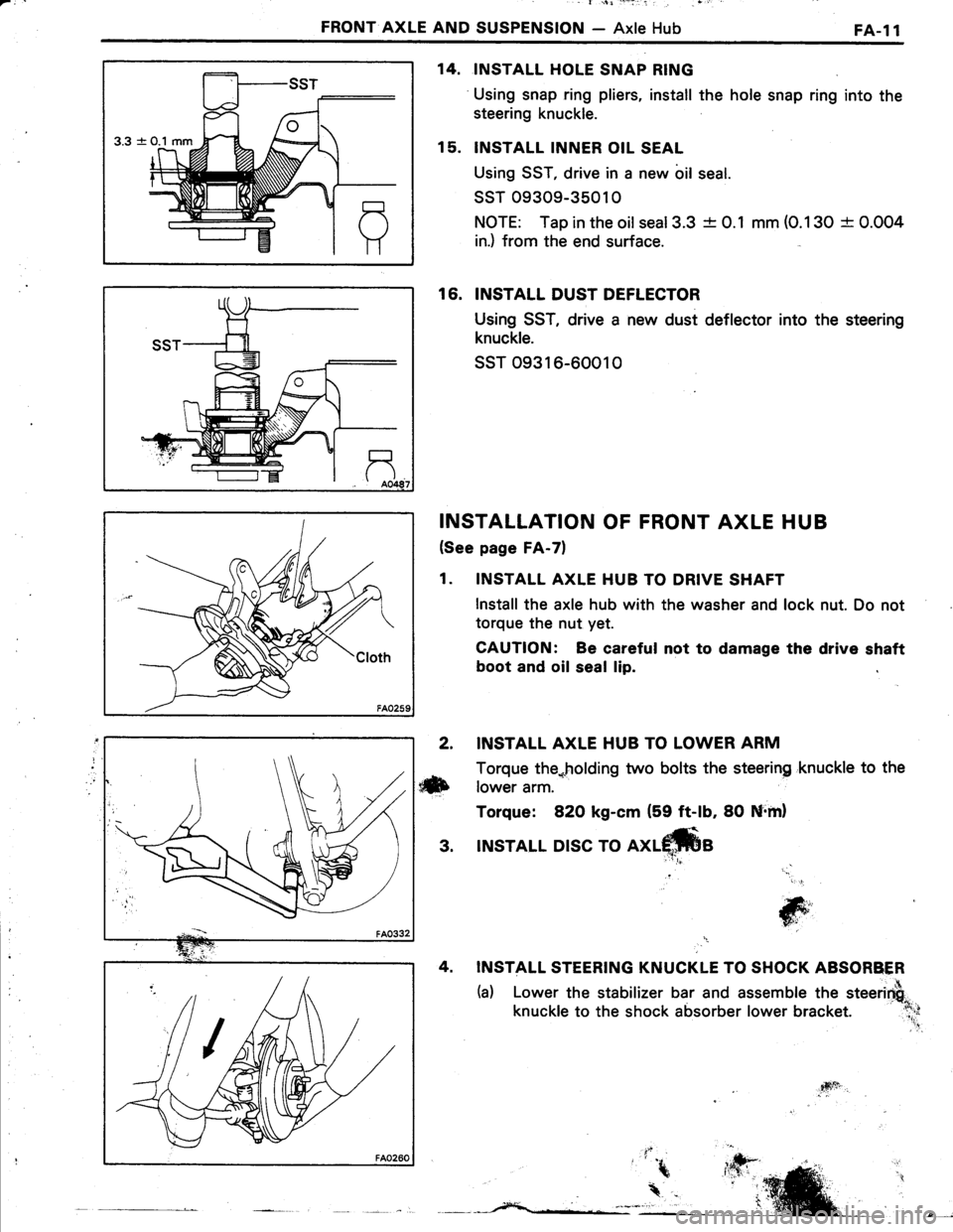
INSTALL HOLE SNAP RING
Using snap ring pliers, install the hole snap ring into the
steering knuckle.
INSTALL INNER OIL SEAL
Using SST, drive in a new bil seal.
ssT 09309-35010
NOTE: Tap in the oilseal3.3 -t- 0.1 mm (O.130 + 0.004
in.) from the end surface.
16. INSTALL DUST DEFLECTOR
Using SST, drive a new dust deflector into the steering
knuckle.
ssT o9316-60010
INSTALLATION OF FRONT AXLE HUB
(See page FA-7)
1. INSTALL AXLE HUB TO DRIVE SHAFT
lnstall the axle hub with the washer and lock nut. Do not
torque the nut yet.
CAUTION: Be careful not to damage the drive shaft
boot and oil seal lip.
14.
15.
2. INSTALL AXLE HUB TO LOWER ARM
Torque the*holding two bolts the steering 'knuckle to the
ilxb rower arm.
Torque: 82O kg-cm (59 ft-lb, 80 Nrml
3. INSTALL DISC TO
INSTALL STEERING KNUCKLE TO SHOCK ABSORBER
(a) Lower the stabilizer bar and assemble the steerirfi"
knuckle to the shock absorber lower bracket. :l;;
'' .!
jG;','
T6i'
4sft
Page 498 of 885

I
FA-l8FRONT AXLE AND SUSPENSION - Front Drive Shaft
Length
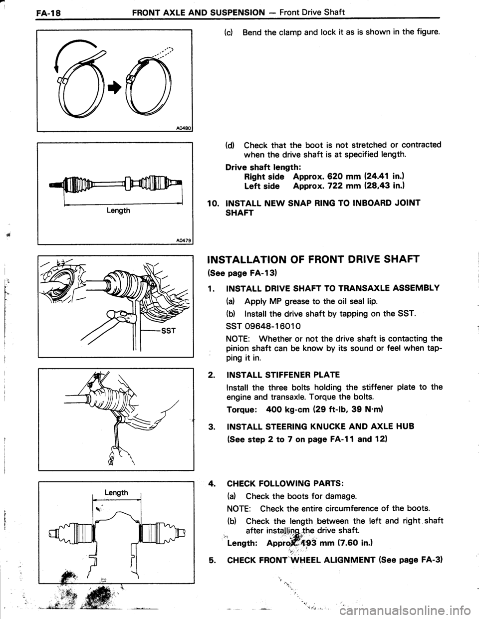
(c) Bend the clamp and lock it as is shown in the figure.
(d) Check that the boot is not stretched or contracted
when the drive shaft is at specified length.
Drive shaft length:
Right side Approx. 620 mm 124.41 in.l
Left side Approx. 722 mm (28,43 in.)
10. INSTALL NEW SNAP RING TO INBOARD JOINT
SHAFT
INSTALLATION OF FRONT DRIVE SHAFT
(See page FA-l3)
1. INSTALL DRIVE SHAFT TO TRANSAXLE ASSEMBLY
(a) Apply MP grease to the oil seal lip.
(b) lnstall the drive shaft by tapping on the SST.
ssT 09648-16010
NOTE: Whether or not the drive shaft is contacting the
pinion shaft can be know by its sound or feel when tap-
ping it in.
INSTALL STIFFENER PLATE
lnstall the three bolts holding the stiffener plate to the
engine and transaxle. Torque the bolts.
Torque: 400 kg-cm (29 ft-lb, 39 N'm)
INSTALL STEERING KNUCKE AND AXLE HUB
(See step 2 to 7 on page FA-l1 and 12)
4. CHECK FOLLOWING PARTS:
(d Check the boots for damage.
NOTE: Check the entire circumference of the boots.
(b) Check the length between the left and right shaft
after installinq,.the drive shaft.i": ' -|*itLength: Approjff{93 mm (7.60 in.)
5. CHECK FRONT"WHEEL ALIGNMENT (See page FA-31
2.
3.
"1.
Page 499 of 885
FRONT AXLE AND SUSPENSION - Front Shock AbsorberFA-l9
FRONT SHOCK ABSORBER
COMPONENTS
REMOVAL DISASSEMBLY OF FRONT SHOCK
ABSORBER ASSEMBLY
1. DISCONNECT STEERING KNUCKLE FROM SHOCK
ABSORBER (See step 6 on page FA-81
2. REMOVE SHOCK ABSORBER ASSEMBLY FROM
BODY ii.
(d Remove the dust cover from the suspqnsion support.
(b) Loosen the nut. Do not remove the nut yH"
$-Dust Cover
o@
g--ZA-r-a
/:A-F Suspension S upport
Ef
@-Dust Seat
@-sprinsseat
W
: Tightening torque
| : Non-reusable part
CoilSpring
(ft-lb. N.m)
Page 500 of 885
FA-20FRONT AXLE AND SUSPENSION - Front Shock Absorber
w/o PS
w/ PS and 4WD
(c) Remove the three nuts holding the shock absorber to
the body.
(d Remove the shock absorber assembly.
CAUTION: Cover the drive shaft boot with cloth to
avoid damage.
3. CLAMP SHOCK ABSORBER IN VISE
Install a bolt and nuts to the bracket at the lower portion of
the shock absorber shell and secure it in a vise.
4, REMOVE COIL SPRING
(d Using SST, compress the coil spring.
ssr 09727 -22032
(b) Hold the suspension with a screwdriver or such so
that it will not turn, and then remove the support nut.
(c) Remove the suspension support, spring seat, spring
and dust cover.
tr-;
W
Page 501 of 885

FRONT AXLE AND SUSPENSION - Front Shock AbsorberFA.21
INSPECTION OF FRONT SHOCK ABSORBER
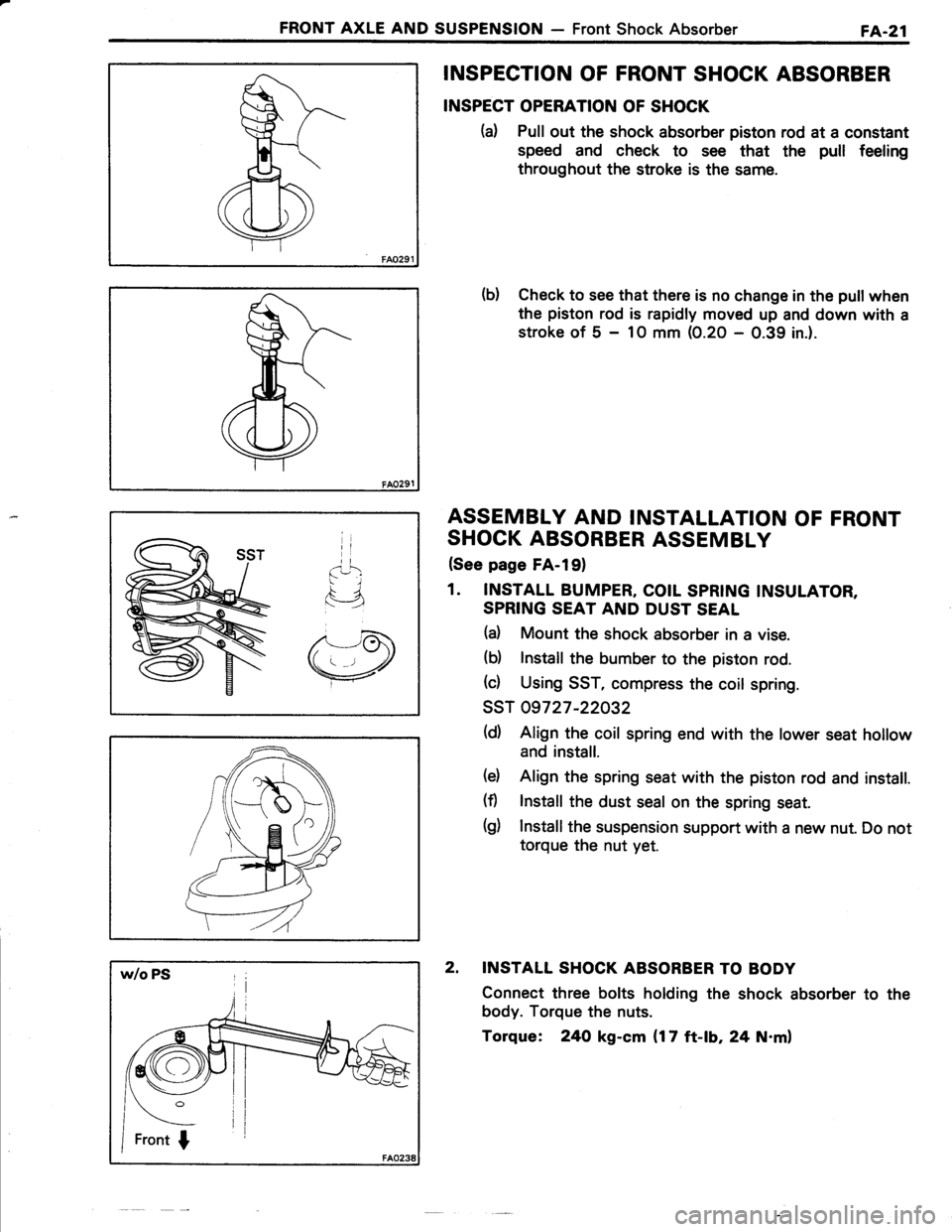
INSPECT OPERATION OF SHOCK
(d Pull out the shock absorber piston rod at a constant
speed and check to see that the pull feeling
throughout the stroke is the same.
b) Check to see that there is no change in the pull when
the piston rod is rapidly moved up and down with a
stroke of 5 - 1O mm (0.20 - 0.39 in.).
ASSEMBLY AND INSTALLATION OF FRONT
SHOCK ABSORBER ASSEMBLY
(See page FA-l91
1. INSTALL BUMPER, COIL SPRING INSULATOR,
SPRING SEAT AND DUST SEAL
(d Mount the shock absorber in a vise.
(b) lnstall the bumber to the piston rod.
(c) Using SST, compress the coil spring.
ssT 09727 -22032
(d) Align the coil spring end with the lower seat hollow
and install.
(d Align the spring seat with the piston rod and install.
(fl lnstall the dust seal on the spring seat.
(g) Install the suspension support with a new nut. Do not
torque the nut yet.
2. INSTALL SHOCK ABSORBER TO BODY
Connect three bolts holding the shock absorber to the
body. Torque the nuts.
Torque: 24O kg-cm {17 ft-lb, 24 N.ml