Page 518 of 885
r.1
E4-10 REAR AXLE AND SUSPENSION - Rear Axle Hub and Canier (FWD)
(b) Snug down the bearing by turning the hub several
times.
(c) Loosen the nut until it can be turned by hand.
NOTE: Make sure that there is absolutely no brake drag.
(d) Measure and make a note of the rotation frictional
force of the oil seal.
Oil sealfrictionalforce: Approx. rtoog (0.9 lb, 3.9 Nl
(e) Tighten the nut until the preload is within specifica-
tion.
Bearing preload (while turning):
In addition to oil seal frictional force
400 - 1,000 g (0.9 - 2.2 tb,3.9 - 9.8 Nl
(fl Insure that the drum rotates smoothly.
6. INSTALL NUT LOCK, COTTER PIN AND CAP
NOTE: lf the cotter pin hole does not line up, correct by
tightening the nut the smallest amount possible.
7. FILL BRAKE RESERVOIR WITH BRAKE FLUID AND
BLEED BRAKE SYSTEM (See page BR-ZI
Page 523 of 885
REAR AXLE AND susPENstoN - Rear Axle Hub and carrier (FWD) RA-ls
81 104
(c) Install and torque a new nut.
Torque: 1,25,O kg-cm (90 ft-tb, 123 N.ml
(d) Stake the nut.
INSTALLATION OF REAR AXLE HUB AND
CARRIER
(See page RA-l2)
1. INSTALL REAR AXLE CARRIER
(See pages RA-8 and 9l
2. INSTATL REAR AXLE HUB
(a) Install a new O-ring to the axle carrier.
(b) lnstall the axle hub and rear brake assembly with thefour bolts. Torque the bolts.
Torque: 820 kg-cm (59 ft-tb, 80 N.ml
3. CONNECT BRAKE TUBE TO WHEEL CYLINDER
ssT 09751 -3601 1
Torque: 155 kg-cm (t 1 ft-lb, 15 N.m)
4. INSTALL BRAKE DRUM
5. FILL BRAKE RESERVOIR WITH BRAKE FLUID ANDBLEED BRAKE SYSTEM (See page BR-7)
6. TOROUE AXLE CARRIER MOUNT BOLTS
(See page RA-111
7. CHECK REAR WHEEL ALTGNMENT {See page RA-3}
' ,"4' 'r4 "'
Page 528 of 885
RA.20REAR AXLE AND SUSPENSION - Rear Suspension (FWD)
4. TOROUE NUT HOLDING SUSPENSION SUPPORT TO
SHOCK ABSORBER
(a) Torque the nut.
Torque: 500 kg-cm (36 ft-lb, 49 N'ml
(b) Install the dust cover on the suspension support'
5. INSTALL FLEXIBLE HOSE TO SHOCK ABSORBER
BRACKET
6. INSTALL BRAKE TUBE
Torque: 155 kg-cm (1 1 ft-lb, 15 N'm)
7. FILL BRAKE RESERVOIR WITH BRAKE FLUID AND
BLEED BRAKE SYSTEM (See page BR-7)
8. CHECK REAR WHEEL ALIGNMENT (See page RA-3)
9. INSTALL PACKAGE TRAY BRACKET AND SHOCK
ABSORBER
Suspension Arm
(See page RA-l6)
REMOVAL OF SUSPENSION ARM
1. JACK UP VEHICLE
Jack up the vehicle and support the body with stands.
2. REMOVE NO.2 SUSPENSION ARM
(a) Remove the bolt and nut holding the suspension arm
to the axle carrier.
(b) Remove the cam and bolt holding the suspension
arm to the body and remove the suspension arm.
NOTE: (1) Remember where the cam plate mark is
when removing the suspension arm.
Ql When removing, loosen the bolt. Do not turn
the cam.
Page 566 of 885

BRAKE SYSTEM - Checks and AdjustmentsBR-7
@@
VV
1 st 2nd
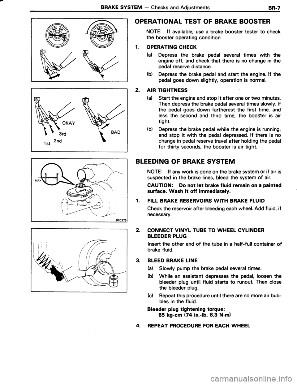
OPERATIONAL TEST OF BRAKE BOOSTER
NOTE: lf available, use a brake booster tester to check
the booster operating condition.
1. OPERATING CHECK
(a) Depress the brake pedal several times with the
engine off, and check that there is no change in the
pedal reserve distance.
(b) Depress the brake pedal and start the engine. lf the
pedal goes down slightly, operation is normal.
2. AIR TIGHTNESS
(d Start the engine and stop it after one or two minutes.
Then depress the brake pedal several times slowly. lf
the pedal goes down fartherest the first time, and
less the second and third time, the boo$ter is air
tight.
(b) Depress the brake pedal while the engine is running,
and stop it with the pedal depressed. lf there is no
change in pedal reserve travel after holding the pedal
for thirty seconds, the booster is air tight.
BLEEDING OF BRAKE SYSTEM
NOTE: lf any work is done on the brake system or if air is
suspected in the brake lines, bleed the system of air.
CAUTION: Do not let brake fluid remain on a painted
surface. Wash it off immediataly.
1. FILL BRAKE RESERVOIRS WITH BRAKE FLUID
Check the reservoir after bleeding each wheel. Add fluid, if
necessary.
2, CONNECT VINYL TUBE TO WHEEL CYLINDER
BLEEDER PLUG
lnsert the other end of the tube in a half-full container of
brake fluid.
3. BLEED BRAKE LINE
(a) Slowly pump the brake pedal several times.
(b) While an assistant depresses the pedal, loosen the
bleeder plug until fluid starts to runout. Then close
the bleeder plug.
(c) Repeat this procedure until there are no more air bub-
bles in the fluid.
Bleeder plug tightening torque:
85 kg-cm (74 in.-lb,8.3 N.m)
4. REPEAT PROCEDURE FOR EACH WHEEL
Page 568 of 885
BRAKE SYSTEM - Master CylinderBR-9
MASTER CYLINDER
REMOVAL OF MASTER CYLINDER
Master Cylinder
Brake Fluid LevelWarning Switch Connectort) Gasket
I
I
s
Brake Tube
-cm (ft-lb,
O: Non-reusable part
1s5 (1 1, 15)
Tightening torque
GAUTION: Do not let brake fluid remain on a painted
surface. Wash it off immediatoly.
1. TAKE OUT FLUID WITH SYRINGE
2. DISCONNECT BRAKE TUBES j ,�.
Usin! SST, disconnect the brake tubes from tfie master
cylinder and 3-way union.
ssT 09751-3601 1
3. REMOVE MASTER CYLINDER
(d Disconnect the brake fluid level warning switch con-
nector.
(b) Remove the two nuts.
(c) Remove the master cylinder, 3-way union and gasket
from the brake booster.
Page 572 of 885
BRAKE SYSTEM - Master CylinderBR-l3
INSTALLATION OF MASTER CYLINDER
(See page BR-91
1. CLEAN OUT GROOVE ON LOWER INSTALLATION
SURFACE OF MASTER CYLINDER
2. CHECK THAT ''VP" MARK ON MASTER CYLINDER
BOOT IS IN CORRECT POSITION
3. ADJUST LENGTH OF BRAKE BOOSTER PUSH ROD
BEFORE INSTALLING MASTER CYLINDER
(See page BR-151
4. INSTALL MASTER CYLINDER
Install a new gasket, the master cylinder and 3-way union
with the two nuts. Torque the nuts.
Torque: 130 kg-cm (9 ft-lb, 13 N.ml
*
5. CONNECT BRAKE TUBES
Using SST, connect the brake tubes to the master cyliner
and 3-way union. Torque the nuts.
ssr 09751-3601 1 ;
Torque: 155 kg-cm (11ft-lb, 15 N'ml
1?
6. FILL BRAKE RESERVOIR WITH BRAKE FLUID
AND BLEED BRAKE SYSTEM {See page BR-71
7. CHECK AND ADJUST BRAKE PEDAL (See page BR-61
Page 573 of 885
8R.14BRAKE SYSTEM - Brake Booster
REMOVAL OF BRAKE BOOSTER
levis
II
dCI
130 (9, 131f=s(lr=' I
5
llJ
3-Way Unionl
(ft-lb, N.m):Tightening torque
0 : Non-reusable part
Brake Fluid Level Warning
Switch Connector
Brake Booster
BRAKE BOOSTER
1. REMOVE MASTER CYLINDER (See page Bn-gl
2. DISCONNECT VACUUM HOSE FROM BRAKE
BOOSTER
3. REMOVE DISTRIBUTOR CAP
4. REPEAT PROCEDURE FOR EACH WHEEL
5. REMOVE HEATER AIR DUCT
6. DISCONNECT PEDAL RETURN SPRING FROM
BRAKE PEDAL
7. DISCONNECT PUSH ROD CLEVIS FROM BRAKE
PEDAL
Remove the clip and clevis pin.
8. REMOVE BRAKE BOOSTER
Remove the four nuts, and pull out the brake booster.
Page 574 of 885

BRAKE SYSTEM - Brake Booster8R.15
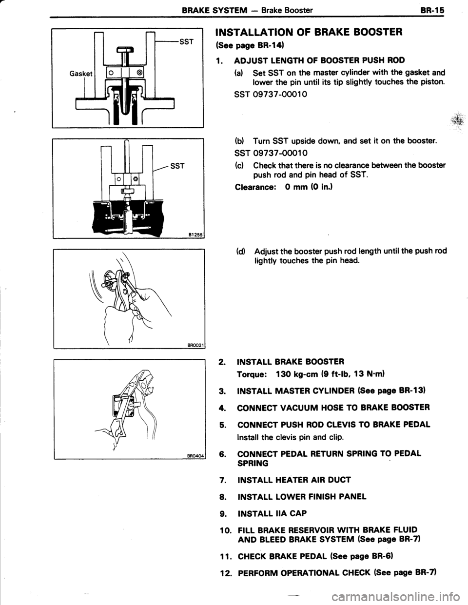
INSTALLATION OF BRAKE BOOSTER
(See page BR-l41
1. ADJUST LENGTH OF BOOSTER PUSH ROD
(a) Set SST on the master cylinder with the gasket and
lower the pin until its tip slightly touches the piston.
ssr 09737-00010
(d Tum SST upside down, and set it on the booster.
ssT 09737-OOO10
(c) Check that there is no clearance between the booster
push rod and pin head of SST.
Clearance: O mm (0 in.l
(d) Adjust the booster push rod length untilthe push rod
lightly touches the pin head.
2. INSTALL BRAKE BOOSTER
Torque: 130 kg-cm (9 ft-lb, 13 N'ml
3. INSTALL MASTER CYLINDER (See page BR-131
4. CONNECT VACUUM HOSE TO BRAKE BOOSTER
5. CONNECT PUSH ROD CLEVIS TO BRAKE PEDAL
Install the clevis pin and clip.
6. CONNECT PEDAL RETURN SPRING TO PEDAL
SPRING
INSTALL HEATER AIR DUCT
INSTALL LOWER FINISH PANEL
INSTALL IIA CAP
FILL BRAKE RESERVOIR WITH BRAKE FLUID
AND BLEED BRAKE SYSTEM (See page BR-71
CHECK BRAKE PEDAL (See page BR-61
PERFORM OPERATIONAL CHECK (See page BR-71
7.
8.
9.
10.
11.
12.