1985 FORD GRANADA wheel torque
[x] Cancel search: wheel torquePage 153 of 255

1With the strut removed, clamp it in a vice
with protected jaws.2Remove the stub axle carrier pinch-bolts.
Spread the carrier by carefully introducing a
chisel or blunt screwdriver into the crack, then
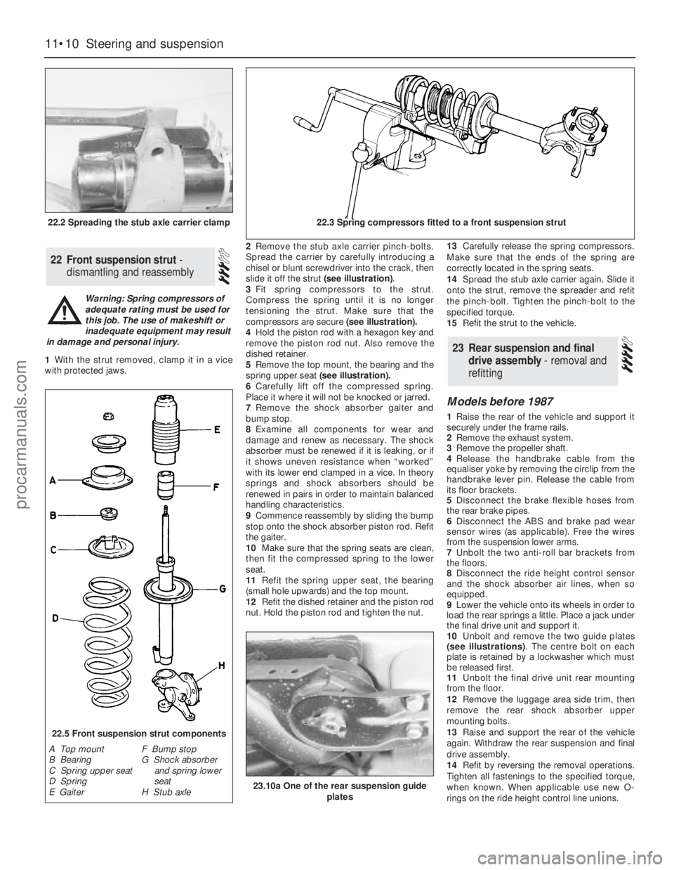
slide it off the strut (see illustration).
3Fit spring compressors to the strut.
Compress the spring until it is no longer
tensioning the strut. Make sure that the
compressors are secure (see illustration).
4Hold the piston rod with a hexagon key and
remove the piston rod nut. Also remove the
dished retainer.
5Remove the top mount, the bearing and the
spring upper seat(see illustration).
6Carefully lift off the compressed spring.
Place it where it will not be knocked or jarred.
7Remove the shock absorber gaiter and
bump stop.
8Examine all components for wear and
damage and renew as necessary. The shock
absorber must be renewed if it is leaking, or if
it shows uneven resistance when “worked”
with its lower end clamped in a vice. In theory
springs and shock absorbers should be
renewed in pairs in order to maintain balanced
handling characteristics.
9Commence reassembly by sliding the bump
stop onto the shock absorber piston rod. Refit
the gaiter.
10Make sure that the spring seats are clean,
then fit the compressed spring to the lower
seat.
11Refit the spring upper seat, the bearing
(small hole upwards) and the top mount.
12Refit the dished retainer and the piston rod
nut. Hold the piston rod and tighten the nut.13Carefully release the spring compressors.
Make sure that the ends of the spring are
correctly located in the spring seats.
14Spread the stub axle carrier again. Slide it
onto the strut, remove the spreader and refit
the pinch-bolt. Tighten the pinch-bolt to the
specified torque.
15Refit the strut to the vehicle.
Models before 1987
1Raise the rear of the vehicle and support it
securely under the frame rails.
2Remove the exhaust system.
3Remove the propeller shaft.
4Release the handbrake cable from the
equaliser yoke by removing the circlip from the
handbrake lever pin. Release the cable from
its floor brackets.
5Disconnect the brake flexible hoses from
the rear brake pipes.
6Disconnect the ABS and brake pad wear
sensor wires (as applicable). Free the wires
from the suspension lower arms.
7Unbolt the two anti-roll bar brackets from
the floors.
8Disconnect the ride height control sensor
and the shock absorber air lines, when so
equipped.
9Lower the vehicle onto its wheels in order to
load the rear springs a little. Place a jack under
the final drive unit and support it.
10Unbolt and remove the two guide plates
(see illustrations). The centre bolt on each
plate is retained by a lockwasher which must
be released first.
11Unbolt the final drive unit rear mounting
from the floor.
12Remove the luggage area side trim, then
remove the rear shock absorber upper
mounting bolts.
13Raise and support the rear of the vehicle
again. Withdraw the rear suspension and final
drive assembly.
14Refit by reversing the removal operations.
Tighten all fastenings to the specified torque,
when known. When applicable use new O-
rings on the ride height control line unions.
23Rear suspension and final
drive assembly - removal and
refitting
22Front suspension strut -
dismantling and reassembly
11•10Steering and suspension
22.2 Spreading the stub axle carrier clamp22.3 Spring compressors fitted to a front suspension strut
22.5 Front suspension strut components
A Top mount
B Bearing
C Spring upper seat
D Spring
E GaiterF Bump stop
G Shock absorber
and spring lower
seat
H Stub axle
Warning: Spring compressors of
adequate rating must be used for
this job. The use of makeshift or
inadequate equipment may result
in damage and personal injury.
23.10a One of the rear suspension guide
plates
procarmanuals.com
Page 154 of 255

15Bleed the brake hydraulic system and
adjust the handbrake on completion.
Models from 1987
16From 1987, the tab washer which secures
the guide plate centre bolt on each side has
been deleted. A self-locking bolt and plain
washer are used instead.
17The new bolt and washer should be fitted
to earlier models if the old bolt has been
removed for any reason. The tab washer
should be discarded.
18The tightening torque for the new bolt
remains the same as that given for the original.
1Remove the wheel trim. Apply the
handbrake and chock the front wheels.
2Slacken the driveshaft stub axle. This nut is
very tight. The left-hand nut has aleft-hand
thread, therefore it is undone clockwise.
3Remove the brake disc.
4Remove the driveshaft stub axle.
5Remove the four bolts which secure the
hub. Pull the hub off the driveshaft stub,
leaving the disc splash shield loose.
6Refit by reversing the removal operations.
Carry out the final tightening of the driveshaft
stub nut with the wheels on the ground.
1Remove the rear hub as described in the
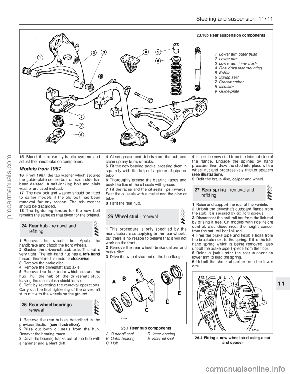
previous Section (see illustration).
2Prise out both oil seals from the hub.
Recover the bearing races.
3Drive the bearing tracks out of the hub with
a hammer and a blunt drift.4Clean grease and debris from the hub and
clean up any burrs or nicks.
5Fit the new bearing tracks, pressing them in
squarely with the help of a piece of pipe or
tube.
6Thoroughly grease the bearing races and
pack the lips of the oil seals with grease.
7Fit the races and the oil seals, lips inwards.
Seat the oil seals with a mallet and the pipe or
tube.
8Refit the rear hub.
1This procedure is only specified by the
manufacturers as applying to the rear wheels,
but there is no reason to believe that it will not
work on the front.
2Remove the rear wheel, brake caliper and
brake disc.
3Drive the wheel stud out of the hub flange. 4Insert the new stud from the inboard side of
the flange. Engage the splines by hand
pressure, then draw the stud into place with a
wheel nut and progressively thicker spacers
(see illustration).
5Refit the brake disc, caliper and wheel.
1Raise and support the rear of the vehicle.
2Unbolt the driveshaft outboard flange from
the stub. It is secured by six Torx screws.
3Disconnect the anti-roll bar from the link rod
by prising it free. On models with ride height
control, also disconnect the height sensor
from the anti-roll bar link rod.
4Free the brake pipe and flexible hose from
the brackets next to the spring. If it is the left-
hand spring which is being removed, also
unbolt the brake pipe T-piece from the floor.
5Raise a jack under the rear suspension
lower arm to load the spring.
6Unbolt the shock absorber from the lower
arm.
27Rear spring - removal and
refitting
26Wheel stud - renewal
25Rear wheel bearings -
renewal
24Rear hub - removal and
refitting
Steering and suspension 11•11
11
25.1 Rear hub components
A Outer oil seal
B Outer bearing
C HubD Inner bearing
E Inner oil seal26.4 Fitting a new wheel stud using a nut
and spacer
23.10b Rear suspension components
1 Lower arm outer bush
2 Lower arm
3 Lower arm inner bush
4 Final drive rear mounting
5 Buffer
6 Spring seat
7 Crossmember
8 Insulator
9 Guide plate
procarmanuals.com
Page 155 of 255

7Unbolt the guide plate from the body on the
side concerned.
8Carefully lower the jack until the spring is no
longer under tension. Remove the spring and
the rubber buffer.
9Refit by reversing the removal operations,
tightening all fastenings to the specified torque
when known.
Note: Ford tool No 15-014, or locally made
equivalent, will be required for this job.
1Raise and support the rear of the vehicle.
2Flatten the lockwasher which secures the
guide plate centre bolt. Remove the centre
bolt and the two bolts which hold the guide
plate to the floor; remove the guide plate.
3Wedge a piece of wood between the
crossmember and the floor.
4Draw the insulator out with the special tool
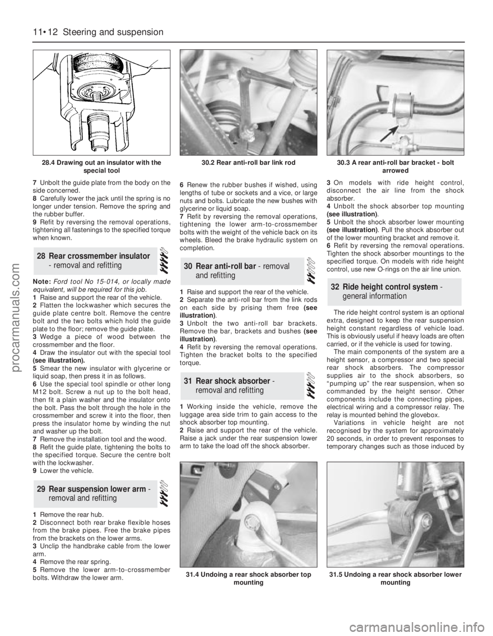
(see illustration).
5Smear the new insulator with glycerine or
liquid soap, then press it in as follows.
6Use the special tool spindle or other long
M12 bolt. Screw a nut up to the bolt head,
then fit a plain washer and the insulator onto
the bolt. Pass the bolt through the hole in the
crossmember and screw it into the floor, then
press the insulator home by winding the nut
and washer up the bolt.
7Remove the installation tool and the wood.
8Refit the guide plate, tightening the bolts to
the specified torque. Secure the centre bolt
with the lockwasher.
9Lower the vehicle.
1Remove the rear hub.
2Disconnect both rear brake flexible hoses
from the brake pipes. Free the brake pipes
from the brackets on the lower arms.
3Unclip the handbrake cable from the lower
arm.
4Remove the rear spring.
5Remove the lower arm-to-crossmember
bolts. Withdraw the lower arm.6Renew the rubber bushes if wished, using
lengths of tube or sockets and a vice, or large
nuts and bolts. Lubricate the new bushes with
glycerine or liquid soap.
7Refit by reversing the removal operations,
tightening the lower arm-to-crossmember
bolts with the weight of the vehicle back on its
wheels. Bleed the brake hydraulic system on
completion.
1Raise and support the rear of the vehicle.
2Separate the anti-roll bar from the link rods
on each side by prising them free (see
illustration).
3Unbolt the two anti-roll bar brackets.
Remove the bar, brackets and bushes (see
illustration).
4Refit by reversing the removal operations.
Tighten the bracket bolts to the specified
torque.
1Working inside the vehicle, remove the
luggage area side trim to gain access to the
shock absorber top mounting.
2Raise and support the rear of the vehicle.
Raise a jack under the rear suspension lower
arm to take the load off the shock absorber.3On models with ride height control,
disconnect the air line from the shock
absorber.
4Unbolt the shock absorber top mounting
(see illustration).
5Unbolt the shock absorber lower mounting
(see illustration). Pull the shock absorber out
of the lower mounting bracket and remove it.
6Refit by reversing the removal operations.
Tighten the shock absorber mountings to the
specified torque. On models with ride height
control, use new O-rings on the air line union.
The ride height control system is an optional
extra, designed to keep the rear suspension
height constant regardless of vehicle load.
This is obviously useful if heavy loads are often
carried, or if the vehicle is used for towing.
The main components of the system are a
height sensor, a compressor and two special
rear shock absorbers. The compressor
supplies air to the shock absorbers, so
“pumping up” the rear suspension, when so
commanded by the height sensor. Other
components include the connecting pipes,
electrical wiring and a compressor relay. The
relay is mounted behind the glovebox.
Variations in vehicle height are not
recognised by the system for approximately
20 seconds, in order to prevent responses to
temporary changes such as those induced by
32Ride height control system -
general information
31Rear shock absorber -
removal and refitting
30Rear anti-roll bar - removal
and refitting
29Rear suspension lower arm -
removal and refitting
28Rear crossmember insulator
- removal and refitting
11•12Steering and suspension
28.4 Drawing out an insulator with the
special tool
31.4 Undoing a rear shock absorber top
mounting31.5 Undoing a rear shock absorber lower
mounting
30.2 Rear anti-roll bar link rod30.3 A rear anti-roll bar bracket - bolt
arrowed
procarmanuals.com
Page 158 of 255

Chapter 12
Bodywork and fittings
Bonnet - removal and refitting . . . . . . . . . . . . . . . . . . . . . . . . . . . . . .6
Bonnet insulation panel - removal and refitting . . . . . . . . . . . . . . . .26
Bonnet release cable - removal and refitting . . . . . . . . . . . . . . . . . .11
Boot lid lock barrel - removal and refitting . . . . . . . . . . . . . . . . . . . .18
Boot lid - removal, refitting and adjustment . . . . . . . . . . . . . . . . . . . .9
Bumper mouldings - removal and refitting . . . . . . . . . . . . . . . . . . . .36
Bumpers - removal and refitting . . . . . . . . . . . . . . . . . . . . . . . . . . . .35
Centre console - removal and refitting . . . . . . . . . . . . . . . . . . . . . . .42
Door - removal and refitting . . . . . . . . . . . . . . . . . . . . . . . . . . . . . . . .7
Door exterior handle - removal and refitting . . . . . . . . . . . . . . . . . .13
Door interior trim panel - removal and refitting . . . . . . . . . . . . . . . .22
Door latch assembly - removal and refitting . . . . . . . . . . . . . . . . . .15
Door lock barrel - removal and refitting . . . . . . . . . . . . . . . . . . . . . .14
Door striker plate - adjustment . . . . . . . . . . . . . . . . . . . . . . . . . . . . .12
Door weatherstrip - removal and refitting . . . . . . . . . . . . . . . . . . . .16
Door window frame mouldings - removal and refitting . . . . . . . . . .31
Door window glass - removal and refitting . . . . . . . . . . . . . . . . . . . .23
Door window regulator mechanism - removal and refitting . . . . . . .24
Exterior mirror - removal and refitting . . . . . . . . . . . . . . . . . . . . . . .39
Facia panels and trim - removal and refitting . . . . . . . . . . . . . . . . . .41
Front bumper - height adjustment . . . . . . . . . . . . . . . . . . . . . . . . . .34
Front seat - removal and refitting . . . . . . . . . . . . . . . . . . . . . . . . . . .44
Front seat air cushion - removal and refitting . . . . . . . . . . . . . . . . .45
Front seat belts - removal and refitting . . . . . . . . . . . . . . . . . . . . . .47
Front spoiler - removal and refitting . . . . . . . . . . . . . . . . . . . . . . . . .37Fuel filler lock barrel - removal and refitting . . . . . . . . . . . . . . . . . . .21
General information . . . . . . . . . . . . . . . . . . . . . . . . . . . . . . . . . . . . . .1
Headlining - removal and refitting . . . . . . . . . . . . . . . . . . . . . . . . . .38
Interior mirror - removal and refitting . . . . . . . . . . . . . . . . . . . . . . . .40
Maintenance - bodywork and underframe . . . . . . . . . . . . . . . . . . . . .2
Maintenance - upholstery and carpets . . . . . . . . . . . . . . . . . . . . . . . .3
Major body damage - repair . . . . . . . . . . . . . . . . . . . . . . . . . . . . . . . .5
Minor body damage - repair . . . . . . . . . . . . . . . . . . . . . . . . . . . . . . . .4
Motifs and emblems - removal and refitting . . . . . . . . . . . . . . . . . .33
Overhead console - removal and refitting . . . . . . . . . . . . . . . . . . . .43
Radiator grille - removal and refitting . . . . . . . . . . . . . . . . . . . . . . . .27
Rear parcel shelf - removal and refitting . . . . . . . . . . . . . . . . . . . . .50
Rear quarter window moulding - removal and refitting . . . . . . . . . .32
Rear seat belts - removal and refitting . . . . . . . . . . . . . . . . . . . . . . .48
Rear seat components - removal and refitting . . . . . . . . . . . . . . . . .49
Seat belts - care and maintenance . . . . . . . . . . . . . . . . . . . . . . . . .46
Side mouldings - removal and refitting . . . . . . . . . . . . . . . . . . . . . .28
Sliding roof - removal and refitting . . . . . . . . . . . . . . . . . . . . . . . . . .10
Tailgate - removal and refitting . . . . . . . . . . . . . . . . . . . . . . . . . . . . . .8
Tailgate latch assembly - removal and refitting . . . . . . . . . . . . . . . .19
Tailgate lock barrel - removal and refitting . . . . . . . . . . . . . . . . . . . .17
Tailgate strut - removal and refitting . . . . . . . . . . . . . . . . . . . . . . . .20
Tailgate window mouldings - removal and refitting . . . . . . . . . . . . .30
Windscreen and fixed glass - removal and refitting . . . . . . . . . . . . .25
Windscreen mouldings - removal and refitting . . . . . . . . . . . . . . . .29
Torque wrench settingsNm lbf ft
Front seat belt buckle to seat frame . . . . . . . . . . . . . . . . . . . . . . . . . . . . 51 to 64 38 to 47
Seat belt retractor bolts (front and rear) . . . . . . . . . . . . . . . . . . . . . . . . . 25 to 45 18 to 33
Other seat belt anchorages . . . . . . . . . . . . . . . . . . . . . . . . . . . . . . . . . . 25 to 45 18 to 33
Rear seat back hinge to body . . . . . . . . . . . . . . . . . . . . . . . . . . . . . . . . . 21 to 25 16 to 18
Rear seat back latch striker . . . . . . . . . . . . . . . . . . . . . . . . . . . . . . . . . . 40 to 60 30 to 44
Front seat retaining bolts . . . . . . . . . . . . . . . . . . . . . . . . . . . . . . . . . . . . 25 to 32 18 to 24
Front seat frame-to-slide bolts . . . . . . . . . . . . . . . . . . . . . . . . . . . . . . . . 25 to 32 18 to 24
Rear bumper mountings . . . . . . . . . . . . . . . . . . . . . . . . . . . . . . . . . . . . . 21 16
Front bumper adjuster lockbolt . . . . . . . . . . . . . . . . . . . . . . . . . . . . . . . 21 16
12•1
Easy,suitable for
novice with little
experienceFairly easy,suitable
for beginner with
some experienceFairly difficult,
suitable for competent
DIY mechanicDifficult,suitable for
experienced DIY
mechanicVery difficult,
suitable for expert
DIY or professional
Degrees of difficulty
Specifications Contents
12
The bodyshell and floorpan are of pressed
steel, and form an integral part of the vehicle’s
structure. Various reinforcing and mounting
components beneath the floorpan are made of
HSLA (High Strength Low Alloy) and REPHOS
(rephosphorised) steels, which have superiorstrength-to-weight characteristics when
compared with conventional steels.
Extensive use is made of plastic for
peripheral components such as the radiator
grille, bumpers and wheel trims, and for much
of the interior trim.
Interior fittings are to the high standard
expected in a vehicle of this class, with even
the basic level models well equipped. A wide
range of options is available, including air
conditioning and leather upholstery.The general condition of a vehicle’s
bodywork is the one thing that significantly
affects its value. Maintenance is easy, but
needs to be regular. Neglect, particularly after
minor damage, can lead quickly to further
deterioration and costly repair bills. It is
2 Maintenance - bodywork and
underframe1 General information
procarmanuals.com