1985 FORD GRANADA set clock
[x] Cancel search: set clockPage 198 of 255

8If a new unit has been fitted, trim it by tuning
in a weak medium wave station (around 1500
kHz/200 m) and turning the trimmer screw in
either direction until the best reception is
obtained. On the radio originally fitted, the
trimmer screw is on the front face of the unit;
for other types of radio, consult the
manufacturer’s instructions. Electronic units
are normally self-trimming.
Radio/cassette unit
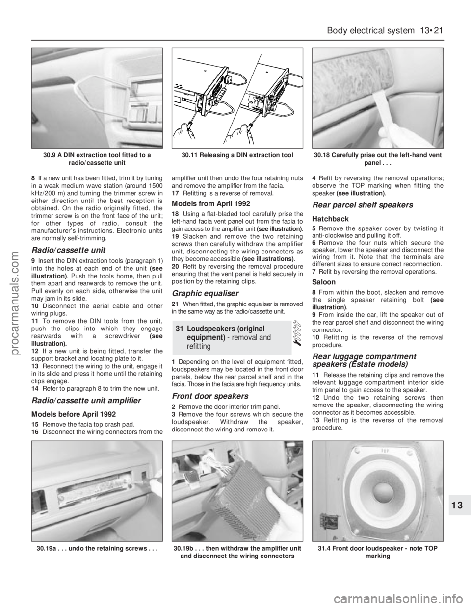
9Insert the DIN extraction tools (paragraph 1)
into the holes at each end of the unit (see
illustration). Push the tools home, then pull
them apart and rearwards to remove the unit.
Pull evenly on each side, otherwise the unit
may jam in its slide.
10Disconnect the aerial cable and other
wiring plugs.
11To remove the DIN tools from the unit,
push the clips into which they engage
rearwards with a screwdriver (see
illustration).
12If a new unit is being fitted, transfer the
support bracket and locating plate to it.
13Reconnect the wiring to the unit, engage it
in its slide and press it home until the retaining
clips engage.
14Refer to paragraph 8 to trim the new unit.
Radio/cassette unit amplifier
Models before April 1992
15Remove the facia top crash pad.
16Disconnect the wiring connectors from theamplifier unit then undo the four retaining nuts
and remove the amplifier from the facia.
17Refitting is a reverse of removal.
Models from April 1992
18Using a flat-bladed tool carefully prise the
left-hand facia vent panel out from the facia to
gain access to the amplifier unit (see illustration).
19Slacken and remove the two retaining
screws then carefully withdraw the amplifier
unit, disconnecting the wiring connectors as
they become accessible (see illustrations).
20Refit by reversing the removal procedure
ensuring that the vent panel is held securely in
position by the retaining clips.
Graphic equaliser
21When fitted, the graphic equaliser is removed
in the same way as the radio/cassette unit.
1Depending on the level of equipment fitted,
loudspeakers may be located in the front door
panels, below the rear parcel shelf and in the
facia. Those in the facia are high frequency units.
Front door speakers
2Remove the door interior trim panel.
3Remove the four screws which secure the
loudspeaker. Withdraw the speaker,
disconnect the wiring and remove it.4Refit by reversing the removal operations;
observe the TOP marking when fitting the
speaker (see illustration).
Rear parcel shelf speakers
Hatchback
5Remove the speaker cover by twisting it
anti-clockwise and pulling it off.
6Remove the four nuts which secure the
speaker, lower the speaker and disconnect the
wiring from it. Note that the terminals are
different sizes to ensure correct reconnection.
7Refit by reversing the removal operations.
Saloon
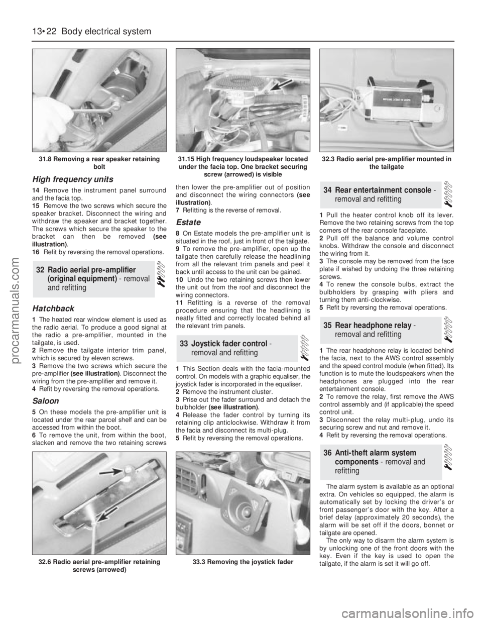
8From within the boot, slacken and remove
the single speaker retaining bolt (see
illustration).
9From inside the car, lift the speaker out of
the rear parcel shelf and disconnect the wiring
connector.
10Refitting is the reverse of the removal
procedure.
Rear luggage compartment
speakers (Estate models)
11Release the retaining clips and remove the
relevant luggage compartment interior side
trim panel to gain access to the speaker.
12Undo the two retaining screws then
remove the speaker, disconnecting the wiring
connector as it becomes accessible.
13Refitting is the reverse of the removal
procedure.
31Loudspeakers (original
equipment) - removal and
refitting
Body electrical system 13•21
13
30.9 A DIN extraction tool fitted to a
radio/cassette unit30.11 Releasing a DIN extraction tool30.18 Carefully prise out the left-hand vent
panel . . .
30.19a . . . undo the retaining screws . . .30.19b . . . then withdraw the amplifier unit
and disconnect the wiring connectors31.4 Front door loudspeaker - note TOP
marking
procarmanuals.com
Page 199 of 255

High frequency units
14Remove the instrument panel surround
and the facia top.
15Remove the two screws which secure the
speaker bracket. Disconnect the wiring and
withdraw the speaker and bracket together.
The screws which secure the speaker to the
bracket can then be removed (see
illustration).
16Refit by reversing the removal operations.
Hatchback
1The heated rear window element is used as
the radio aerial. To produce a good signal at
the radio a pre-amplifier, mounted in the
tailgate, is used.
2Remove the tailgate interior trim panel,
which is secured by eleven screws.
3Remove the two screws which secure the
pre-amplifier (see illustration). Disconnect the
wiring from the pre-amplifier and remove it.
4Refit by reversing the removal operations.
Saloon
5On these models the pre-amplifier unit is
located under the rear parcel shelf and can be
accessed from within the boot.
6To remove the unit, from within the boot,
slacken and remove the two retaining screwsthen lower the pre-amplifier out of position
and disconnect the wiring connectors (see
illustration).
7Refitting is the reverse of removal.
Estate
8On Estate models the pre-amplifier unit is
situated in the roof, just in front of the tailgate.
9To remove the pre-amplifier, open up the
tailgate then carefully release the headlining
from all the relevant trim panels and peel it
back until access to the unit can be gained.
10Undo the two retaining screws then lower
the unit out from the roof and disconnect the
wiring connectors.
11Refitting is a reverse of the removal
procedure ensuring that the headlining is
neatly fitted and correctly located behind all
the relevant trim panels.
1This Section deals with the facia-mounted
control. On models with a graphic equaliser, the
joystick fader is incorporated in the equaliser.
2Remove the instrument cluster.
3Prise out the fader surround and detach the
bulbholder (see illustration).
4Release the fader control by turning its
retaining clip anticlockwise. Withdraw it from
the facia and disconnect its multi-plug.
5Refit by reversing the removal operations.1Pull the heater control knob off its lever.
Remove the two retaining screws from the top
corners of the rear console faceplate.
2Pull off the balance and volume control
knobs. Withdraw the console and disconnect
the wiring from it.
3The console may be removed from the face
plate if wished by undoing the three retaining
screws.
4To renew the console bulbs, extract the
bulbholders by grasping with pliers and
turning them anti-clockwise.
5Refit by reversing the removal operations.
1The rear headphone relay is located behind
the facia, next to the AWS control assembly
and the speed control module (when fitted). Its
function is to mute the loudspeakers when the
headphones are plugged into the rear
entertainment console.
2To remove the relay, first remove the AWS
control assembly and (if applicable) the speed
control unit.
3Disconnect the relay multi-plug, undo its
securing screw and nut and remove it.
4Refit by reversing the removal operations.
The alarm system is available as an optional
extra. On vehicles so equipped, the alarm is
automatically set by locking the driver’s or
front passenger’s door with the key. After a
brief delay (approximately 20 seconds), the
alarm will be set off if the doors, bonnet or
tailgate are opened.
The only way to disarm the alarm system is
by unlocking one of the front doors with the
key. Even if the key is used to open the
tailgate, if the alarm is set it will go off.
36Anti-theft alarm system
components - removal and
refitting
35Rear headphone relay -
removal and refitting
34Rear entertainment console -
removal and refitting
33Joystick fader control -
removal and refitting
32Radio aerial pre-amplifier
(original equipment) - removal
and refitting
13•22Body electrical system
31.8 Removing a rear speaker retaining
bolt
32.6 Radio aerial pre-amplifier retaining
screws (arrowed)33.3 Removing the joystick fader
31.15 High frequency loudspeaker located
under the facia top. One bracket securing
screw (arrowed) is visible32.3 Radio aerial pre-amplifier mounted in
the tailgate
procarmanuals.com