1985 FORD GRANADA fuel tank removal
[x] Cancel search: fuel tank removalPage 98 of 255
4With the engine cold, disconnect the cold
air inlet trunking from the spout. Look into the
spout and check that the flap valve is covering
the hot air inlet.
5Start the engine and allow it to idle. Check
that the flap moves to cover the cold air inlet. If
the flap does not move, check the diaphragm
and heat sensor as follows.
6Stop the engine. Disconnect the diaphragm
vacuum pipe from the heat sensor. Apply
vacuum to the diaphragm, using a vacuum
head pump or by connecting the pipe directly
to manifold vacuum. If the flap now moves, the
heat sensor or vacuum line was faulty. If the
flap still does not move, the diaphragm is
faulty or the flap is jammed.
7On completion reconnect the vacuum pipe
and the cold air trunking.
Mechanical
1Carburettor models without air conditioning
are fitted with a mechanical fuel pump, located
on the left-hand side of the engine block.
2To test the pump, disconnect the ignition
coil LT lead. Disconnect the outlet hose from
the pump and place a wad of rag next to the
pump outlet. Take appropriate fire
precautions.
3Have an assistant crank the engine on the
starter. Well-defined spurts of fuel must beejected from the pump outlet - if not, the pump
is probably faulty (or the tank is empty).
Dispose of the fuel-soaked rag safely.
4To remove the fuel pump, first disconnect
the battery negative lead.
5Disconnect and plug the pump inlet and
outlet hoses. Be prepared for fuel spillage.
6Unscrew the two bolts and withdraw the
pump from the cylinder block. Remove the
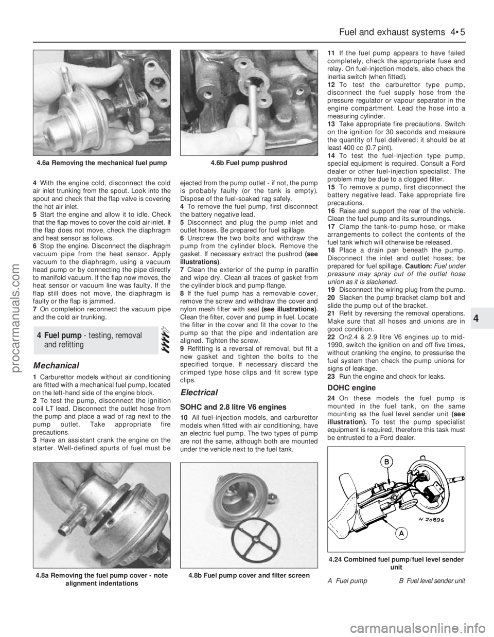
gasket. If necessary extract the pushrod (see
illustrations).
7Clean the exterior of the pump in paraffin
and wipe dry. Clean all traces of gasket from
the cylinder block and pump flange.
8If the fuel pump has a removable cover,
remove the screw and withdraw the cover and
nylon mesh filter with seal (see illustrations).
Clean the filter, cover and pump in fuel. Locate
the filter in the cover and fit the cover to the
pump so that the pipe and indentation are
aligned. Tighten the screw.
9Refitting is a reversal of removal, but fit a
new gasket and tighten the bolts to the
specified torque. If necessary discard the
crimped type hose clips and fit screw type
clips.
Electrical
SOHC and 2.8 litre V6 engines
10All fuel-injection models, and carburettor
models when fitted with air conditioning, have
an electric fuel pump. The two types of pump
are not the same, although both are mounted
under the vehicle next to the fuel tank.11If the fuel pump appears to have failed
completely, check the appropriate fuse and
relay. On fuel-injection models, also check the
inertia switch (when fitted).
12To test the carburettor type pump,
disconnect the fuel supply hose from the
pressure regulator or vapour separator in the
engine compartment. Lead the hose into a
measuring cylinder.
13Take appropriate fire precautions. Switch
on the ignition for 30 seconds and measure
the quantity of fuel delivered: it should be at
least 400 cc (0.7 pint).
14To test the fuel-injection type pump,
special equipment is required. Consult a Ford
dealer or other fuel-injection specialist. The
problem may be due to a clogged filter.
15To remove a pump, first disconnect the
battery negative lead. Take appropriate fire
precautions.
16Raise and support the rear of the vehicle.
Clean the fuel pump and its surroundings.
17Clamp the tank-to-pump hose, or make
arrangements to collect the contents of the
fuel tank which will otherwise be released.
18Place a drain pan beneath the pump.
Disconnect the inlet and outlet hoses; be
prepared for fuel spillage. Caution: Fuel under
pressure may spray out of the outlet hose
union as it is slackened.
19Disconnect the wiring plug from the pump.
20Slacken the pump bracket clamp bolt and
slide the pump out of the bracket.
21Refit by reversing the removal operations.
Make sure that all hoses and unions are in
good condition.
22On2.4 & 2.9 litre V6 engines up to mid-
1990, switch the ignition on and off five times,
without cranking the engine, to pressurise the
fuel system then check the pump unions for
signs of leakage.
23Run the engine and check for leaks.
DOHC engine
24On these models the fuel pump is
mounted in the fuel tank, on the same
mounting as the fuel level sender unit(see
illustration).To test the pump specialist
equipment is required, therefore this task must
be entrusted to a Ford dealer.
4Fuel pump - testing, removal
and refitting
Fuel and exhaust systems 4•5
4
4.6a Removing the mechanical fuel pump4.6b Fuel pump pushrod
4.8a Removing the fuel pump cover - note
alignment indentations4.8b Fuel pump cover and filter screenA Fuel pumpB Fuel level sender unit
4.24 Combined fuel pump/fuel level sender
unit
procarmanuals.com
Page 99 of 255
25To remove the pump, first remove the fuel
tank.
26Unscrew the fuel pump/fuel level sender
unit by engaging two crossed screwdrivers in
the slots on either side of the unit mounting
flange. Recover the seal.
27Refitting is a reversal of removal. It is
necessary to fit a new seal.
1Run the fuel level as low as possible before
removing the tank.
2Disconnect the battery negative lead.
3Remove the fuel filler cap. Siphon or pump
the remaining fuel out of the tank. Store the
fuel in a suitable sealed container.
4Remove the two screws on either side of the
filler neck.
5Raise and support the rear of the vehicle.
6Remove the shield from the right-hand rear
inner wheel arch. Also remove the rear bumper
undershield. which is secured by six screws.
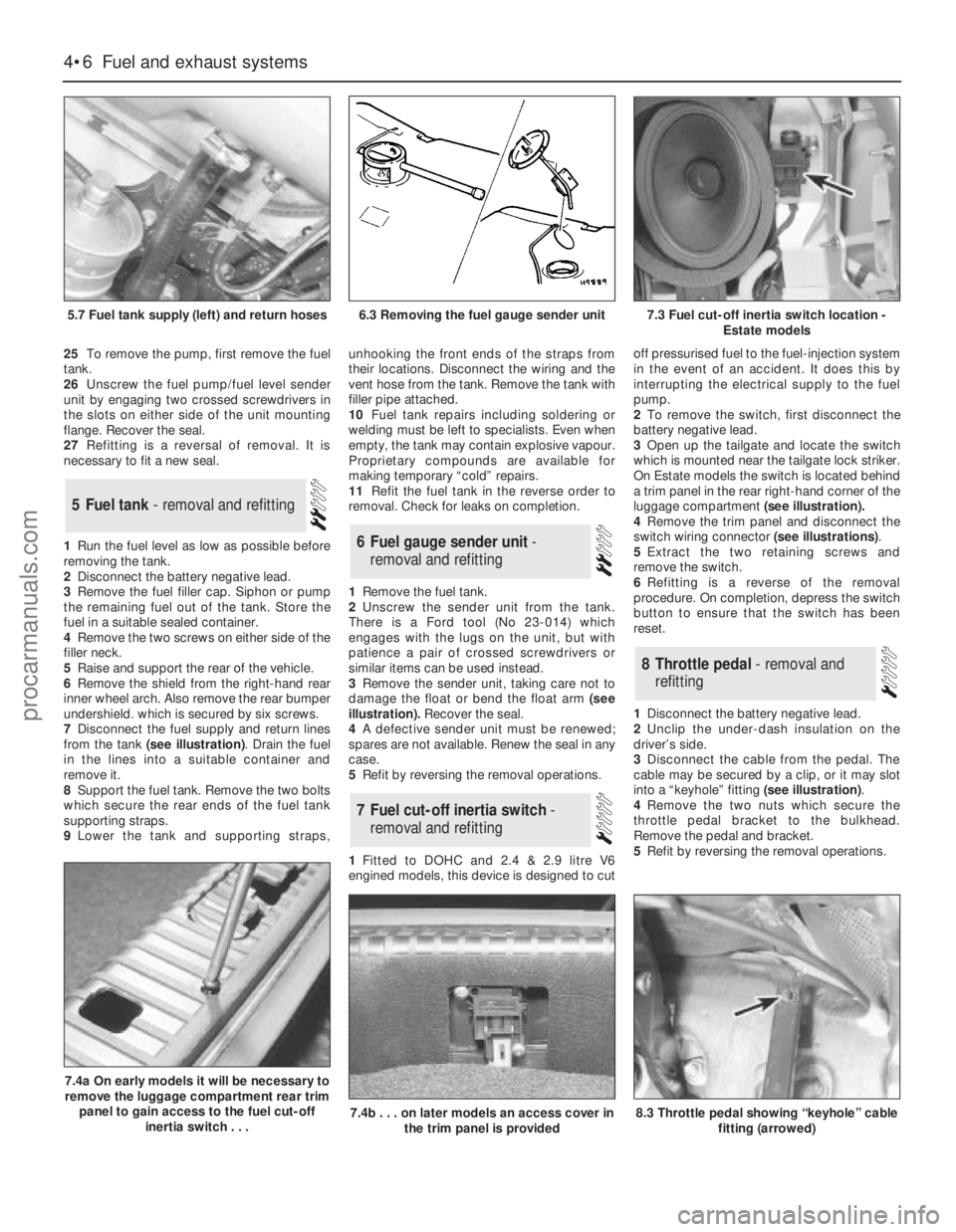
7Disconnect the fuel supply and return lines
from the tank (see illustration). Drain the fuel
in the lines into a suitable container and
remove it.
8Support the fuel tank. Remove the two bolts
which secure the rear ends of the fuel tank
supporting straps.
9Lower the tank and supporting straps,unhooking the front ends of the straps from
their locations. Disconnect the wiring and the
vent hose from the tank. Remove the tank with
filler pipe attached.
10Fuel tank repairs including soldering or
welding must be left to specialists. Even when
empty, the tank may contain explosive vapour.
Proprietary compounds are available for
making temporary “cold” repairs.
11Refit the fuel tank in the reverse order to
removal. Check for leaks on completion.
1Remove the fuel tank.
2Unscrew the sender unit from the tank.
There is a Ford tool (No 23-014) which
engages with the lugs on the unit, but with
patience a pair of crossed screwdrivers or
similar items can be used instead.
3Remove the sender unit, taking care not to
damage the float or bend the float arm(see
illustration).Recover the seal.
4A defective sender unit must be renewed;
spares are not available. Renew the seal in any
case.
5Refit by reversing the removal operations.
1Fitted to DOHC and 2.4 & 2.9 litre V6
engined models, this device is designed to cutoff pressurised fuel to the fuel-injection system
in the event of an accident. It does this by
interrupting the electrical supply to the fuel
pump.
2To remove the switch, first disconnect the
battery negative lead.
3Open up the tailgate and locate the switch
which is mounted near the tailgate lock striker.
On Estate models the switch is located behind
a trim panel in the rear right-hand corner of the
luggage compartment (see illustration).
4Remove the trim panel and disconnect the
switch wiring connector (see illustrations).
5Extract the two retaining screws and
remove the switch.
6Refitting is a reverse of the removal
procedure. On completion, depress the switch
button to ensure that the switch has been
reset.
1Disconnect the battery negative lead.
2Unclip the under-dash insulation on the
driver’s side.
3Disconnect the cable from the pedal. The
cable may be secured by a clip, or it may slot
into a “keyhole” fitting (see illustration).
4Remove the two nuts which secure the
throttle pedal bracket to the bulkhead.
Remove the pedal and bracket.
5Refit by reversing the removal operations.
8Throttle pedal - removal and
refitting
7Fuel cut-off inertia switch -
removal and refitting
6Fuel gauge sender unit -
removal and refitting
5Fuel tank - removal and refitting
4•6Fuel and exhaust systems
5.7 Fuel tank supply (left) and return hoses
7.4a On early models it will be necessary to
remove the luggage compartment rear trim
panel to gain access to the fuel cut-off
inertia switch . . .
7.4b . . . on later models an access cover in
the trim panel is provided8.3 Throttle pedal showing “keyhole” cable
fitting (arrowed)
6.3 Removing the fuel gauge sender unit7.3 Fuel cut-off inertia switch location -
Estate models
procarmanuals.com
Page 100 of 255
1Disconnect the battery negative lead.
2Disconnect the cable from the pedal.
3Working under the bonnet, free the cable
outer from the bulkhead and pull the cable into
the engine bay.
4On carburettor models, remove the air cleaner.5On V6 models, remove the throttle linkage
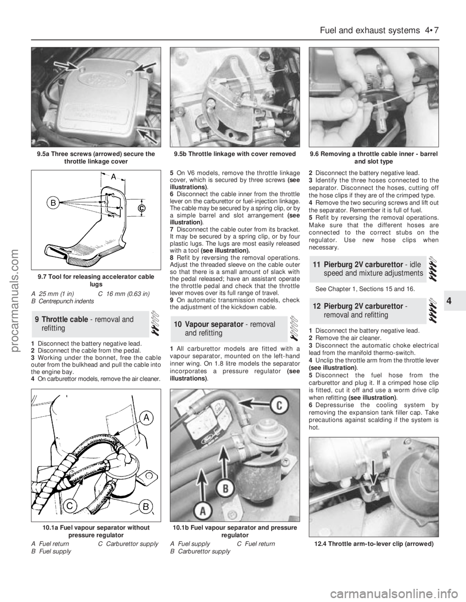
cover, which is secured by three screws (see
illustrations).
6Disconnect the cable inner from the throttle
lever on the carburettor or fuel-injection linkage.
The cable may be secured by a spring clip, or by
a simple barrel and slot arrangement (see
illustration).
7Disconnect the cable outer from its bracket.
It may be secured by a spring clip, or by four
plastic lugs. The lugs are most easily released
with a tool (see illustration).
8Refit by reversing the removal operations.
Adjust the threaded sleeve on the cable outer
so that there is a small amount of slack with
the pedal released; have an assistant operate
the throttle pedal and check that the throttle
lever moves over its full range of travel.
9On automatic transmission models, check
the adjustment of the kickdown cable.
1All carburettor models are fitted with a
vapour separator, mounted on the left-hand
inner wing. On 1.8 litre models the separator
incorporates a pressure regulator (see
illustrations).2Disconnect the battery negative lead.
3Identify the three hoses connected to the
separator. Disconnect the hoses, cutting off
the hose clips if they are of the crimped type.
4Remove the two securing screws and lift out
the separator. Remember it is full of fuel.
5Refit by reversing the removal operations.
Make sure that the different hoses are
connected to the correct stubs on the
regulator. Use new hose clips when
necessary.
See Chapter 1, Sections 15 and 16.
1Disconnect the battery negative lead.
2Remove the air cleaner.
3Disconnect the automatic choke electrical
lead from the manifold thermo-switch.
4Unclip the throttle arm from the throttle lever
(see illustration).
5Disconnect the fuel hose from the
carburettor and plug it. If a crimped hose clip
is fitted, cut it off and use a worm drive clip
when refitting (see illustration).
6Depressurise the cooling system by
removing the expansion tank filler cap. Take
precautions against scalding if the system is
hot.
12Pierburg 2V carburettor -
removal and refitting
11Pierburg 2V carburettor - idle
speed and mixture adjustments
10Vapour separator - removal
and refitting9Throttle cable - removal and
refitting
Fuel and exhaust systems 4•7
4
9.5a Three screws (arrowed) secure the
throttle linkage cover9.5b Throttle linkage with cover removed9.6 Removing a throttle cable inner - barrel
and slot type
12.4 Throttle arm-to-lever clip (arrowed)
9.7 Tool for releasing accelerator cable
lugs
A 25 mm (1 in)
B Centrepunch indentsC 16 mm (0.63 in)
10.1a Fuel vapour separator without
pressure regulator
A Fuel return
B Fuel supplyC Carburettor supply
10.1b Fuel vapour separator and pressure
regulator
A Fuel supply
B Carburettor supplyC Fuel return
procarmanuals.com
Page 116 of 255
Models up to July 1990
1The carbon canister is situated in the engine
compartment where it is mounted onto the
right-hand valance next to the suspension
strut mounting.
2To remove the canister first disconnect the
battery negative terminal. If necessary, undo
the two coolant expansion tank retaining
screws and position the tank clear of the
canister to improve access.
3Disconnect the vacuum hose from the top
of the canister.
4Slacken and remove the mounting bolt and
withdraw the canister from the engine
compartment.
5Refitting is a reverse of the removal
procedure.
Models from July 1990
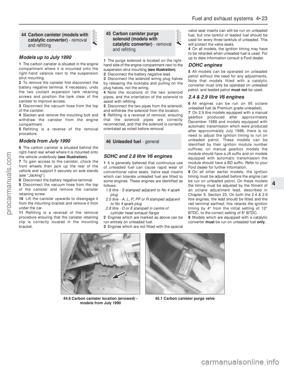
6The carbon canister is situated behind the
right-hand rear wheel where it is mounted onto
the vehicle underbody (see illustration).
7To gain access to the canister, chock the
front wheels then jack up the rear of the
vehicle and support it securely on axle stands
(see “Jacking”).
8Disconnect the battery negative terminal.
9Disconnect the vacuum hose from the top
of the canister and remove the canister
retaining screw.
10Lift the canister upwards to disengage it
from the mounting bracket and remove it from
under the car.
11Refitting is a reversal of the removal
procedure ensuring that the canister retaining
clip is correctly located in the mounting
bracket.1The purge solenoid is located on the right-
hand side of the engine compartment next to the
suspension strut mounting (see illustration).
2Disconnect the battery negative lead.
3Disconnect the solenoid wiring plug halves
by releasing the locktabs and pulling on the
plug halves, not the wiring.
4Note the locations of the two solenoid
pipes, and the orientation of the solenoid to
assist with refitting.
5Disconnect the two pipes from the solenoid,
and withdraw the solenoid from the location.
6Refitting is a reversal of removal, ensuring
that the solenoid pipes are correctly
reconnected, and that the solenoid is correctly
orientated as noted before removal.
SOHC and 2.8 litre V6 engines
1It is generally believed that continuous use
of unleaded fuel can cause rapid wear of
conventional valve seats. Valve seat inserts
which can tolerate unleaded fuel are fitted to
some engines. These engines are identified as
follows:
1.8 litre - S stamped adjacent to No 4 spark
plug
2.0 litre - A, L, P, PP or R stamped adjacent
to No 4 spark plug
2.8 litre - D or E stamped in centre of
cylinder head exhaust flange
2Engines which are marked as above can be
run entirely on unleaded fuel.
3Engines which are not fitted with the specialvalve seat inserts can still be run on unleaded
fuel, but one tankful of leaded fuel should be
used for every three tankfuls of unleaded. This
will protect the valve seats.
4On all models, the ignition timing may have
to be retarded when unleaded fuel is used. For
up to date information consult a Ford dealer.
DOHC engines
5All models can be operated on unleaded
petrol without the need for any adjustments.
Note that models fitted with a catalytic
converter must only be operated on unleaded
petrol, and leaded petrol must notbe used.
2.4 & 2.9 litre V6 engines
6All engines can be run on 95 octane
unleaded fuel (ie Premium grade unleaded).
7On 2.9 litre models equipped with a manual
gearbox produced after approximately
December 1988 and models equipped with
automatic transmission which were produced
after approximately July 1988, there is no
need to adjust the ignition timing to run on
unleaded petrol. These models can be
identified by their ignition module number
suffixes; on manual gearbox models the
module should have a JA suffix and on models
equipped with automatic transmission the
module should have a BD suffix. Refer to your
Ford dealer for further information.
8On all other earlier models, the ignition
timing must be adjusted before the engine can
be run on unleaded petrol. On these models
the timing must be adjusted by the fitment of
an octane adjustment lead, described in
Chapter 5, Section 23. On both the 2.4 & 2.9
litre engines, the lead should be fitted and the
red terminal earthed; this retards the ignition
timing by 4°from the initial setting of 12°
BTDC, to the correct setting of 8°BTDC.
9Models which are equipped with a catalytic
converter must be run on unleaded fuel only.
46Unleaded fuel - general
45Carbon canister purge
solenoid (models with
catalytic converter) - removal
and refitting44Carbon canister (models with
catalytic converter) - removal
and refitting
Fuel and exhaust systems 4•23
4
44.6 Carbon canister location (arrowed) -
models from July 199045.1 Carbon canister purge valve
procarmanuals.com
Page 164 of 255
the door through the large cut-out. Further
displacement or removal of the foamrubber
sheet may be necessary.
7Refit in the reverse order to removal, noting
the following points:
a)Apply a little grease to the interior handle
rods where they pass through the plastic
bushes
b)When securing the interior handle, have
the locking lever in the “unlocked”
position, hold the assembly forwards as
far as itwill go and tighten the securing
screw
c)Check all functions before refitting the trim
panel.
Door weatherstrip
1Open the door and remove the weatherstrip
securing screw from the latch end. In the case
of the rear door, also remove the screw from
the hinge end.
2Carefully lift the latch end of the
weatherstrip and pull it off the door.
3Refit by reversing the removal operations,
using your palm to seat the weatherstrip.
Aperture weatherstrip
4Open the door. Remove the scuff plate
securing screws from the bottom of the door
aperture.
5Pull the old weatherstrip out of the door
aperture.
6Fit the new weatherstrip, starting at the
right-angled corner at the top. Fit the
weatherstrip to the other corners and bends,
leaving the straight sections until last.
7Refit the scuff, plate securing screws.
All models except Estate
1Disconnect the battery negative lead.
2Remove the tailgate interior trim panel,
which is secured by eleven screws.
3Remove the six nuts which secure the
tailgate handle. Remove the handle and
recover the gasket.
4Disconnect the tailgate lock switch multi-
plug. Release the switch locking tab and
remove the switch.
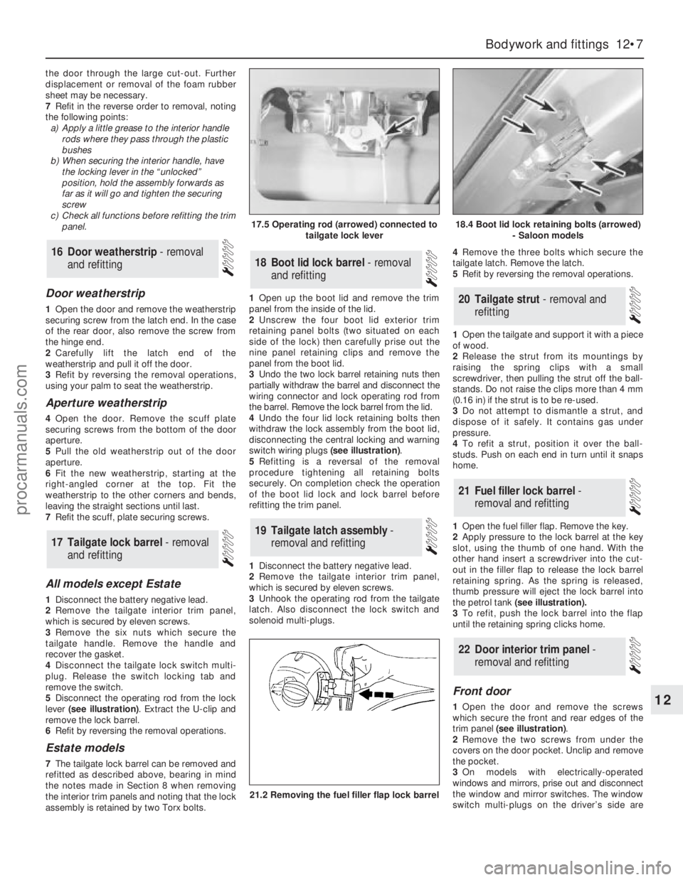
5Disconnect the operating rod from the lock
lever (see illustration). Extract the U-clip and
remove the lock barrel.
6Refit by reversing the removal operations.
Estate models
7The tailgate lock barrel can be removed and
refitted as described above, bearing in mind
the notes made in Section 8 when removing
the interior trim panels and noting that the lock
assembly is retained by two Torx bolts.1Open up the boot lid and remove the trim
panel from the inside of the lid.
2Unscrew the four boot lid exterior trim
retaining panel bolts (two situated on each
side of the lock) then carefully prise out the
nine panel retaining clips and remove the
panel from the boot lid.
3Undo the two lock barrel retaining nuts then
partially withdraw the barrel and disconnect the
wiring connector and lock operating rod from
the barrel. Remove the lock barrel from the lid.
4Undo the four lid lock retaining bolts then
withdraw the lock assembly from the boot lid,
disconnecting the central locking and warning
switch wiring plugs (see illustration).
5Refitting is a reversal of the removal
procedure tightening all retaining bolts
securely. On completion check the operation
of the boot lid lock and lock barrel before
refitting the trim panel.
1Disconnect the battery negative lead.
2Remove the tailgate interior trim panel,
which is secured by eleven screws.
3Unhook the operating rod from the tailgate
latch. Also disconnect the lock switch and
solenoid multi-plugs.4Remove the three bolts which secure the
tailgate latch. Remove the latch.
5Refit by reversing the removal operations.
1Open the tailgate and support it with a piece
of wood.
2Release the strut from its mountings by
raising the spring clips with a small
screwdriver, then pulling the strut off the ball-
stands. Do not raise the clips more than 4 mm
(0.16 in) if the strut is to be re-used.
3Do not attempt to dismantle a strut, and
dispose of it safely. It contains gas under
pressure.
4To refit a strut, position it over the ball-
studs. Push on each end in turn until it snaps
home.
1Open the fuel filler flap. Remove the key.
2Apply pressure to the lock barrel at the key
slot, using the thumb of one hand. With the
other hand insert a screwdriver into the cut-
out in the filler flap to release the lock barrel
retaining spring. As the spring is released,
thumb pressure will eject the lock barrel into
the petrol tank (see illustration).
3To refit, push the lock barrel into the flap
until the retaining spring clicks home.
Front door
1Open the door and remove the screws
which secure the front and rear edges of the
trim panel (see illustration).
2Remove the two screws from under the
covers on the door pocket. Unclip and remove
the pocket.
3On models with electrically-operated
windows and mirrors, prise out and disconnect
the window and mirror switches. The window
switch multi-plugs on the driver’s side are
22Door interior trim panel -
removal and refitting
21Fuel filler lock barrel -
removal and refitting
20Tailgate strut - removal and
refitting
19Tailgate latch assembly -
removal and refitting
18Boot lid lock barrel - removal
and refitting
17Tailgate lock barrel - removal
and refitting
16Door weatherstrip - removal
and refitting
Bodywork and fittings 12•7
12
17.5 Operating rod (arrowed) connected to
tailgate lock lever18.4 Boot lid lock retaining bolts (arrowed)
- Saloon models
21.2 Removing the fuel filler flap lock barrel
procarmanuals.com
Page 194 of 255
Estate
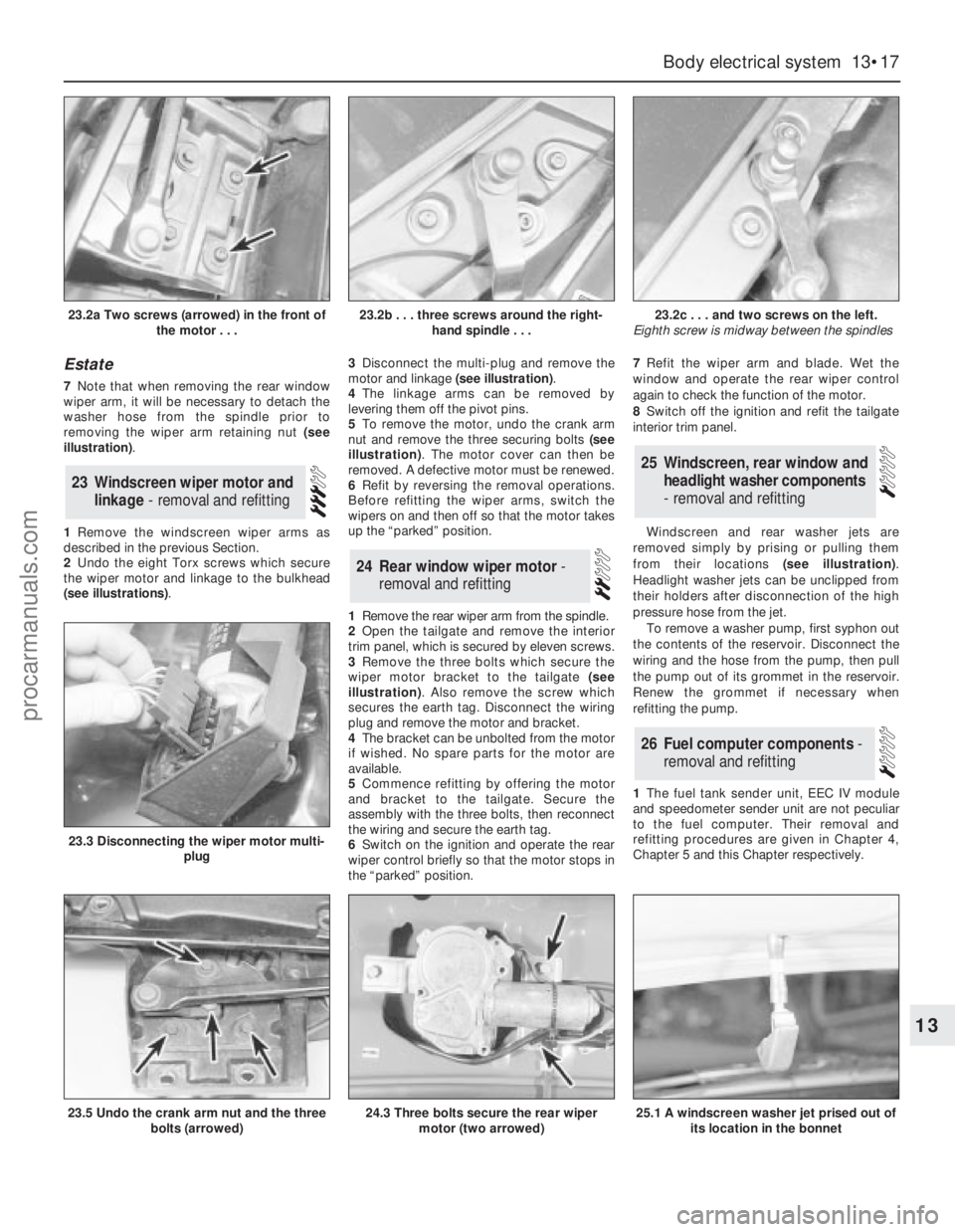
7Note that when removing the rear window
wiper arm, it will be necessary to detach the
washer hose from the spindle prior to
removing the wiper arm retaining nut (see
illustration).
1Remove the windscreen wiper arms as
described in the previous Section.
2Undo the eight Torx screws which secure
the wiper motor and linkage to the bulkhead
(see illustrations).3Disconnect the multi-plug and remove the
motor and linkage (see illustration).
4The linkage arms can be removed by
levering them off the pivot pins.
5To remove the motor, undo the crank arm
nut and remove the three securing bolts (see
illustration). The motor cover can then be
removed. A defective motor must be renewed.
6Refit by reversing the removal operations.
Before refitting the wiper arms, switch the
wipers on and then off so that the motor takes
up the “parked” position.
1Remove the rear wiper arm from the spindle.
2Open the tailgate and remove the interior
trim panel, which is secured by eleven screws.
3Remove the three bolts which secure the
wiper motor bracket to the tailgate (see
illustration). Also remove the screw which
secures the earth tag. Disconnect the wiring
plug and remove the motor and bracket.
4The bracket can be unbolted from the motor
if wished. No spare parts for the motor are
available.
5Commence refitting by offering the motor
and bracket to the tailgate. Secure the
assembly with the three bolts, then reconnect
the wiring and secure the earth tag.
6Switch on the ignition and operate the rear
wiper control briefly so that the motor stops in
the “parked” position.7Refit the wiper arm and blade. Wet the
window and operate the rear wiper control
again to check the function of the motor.
8Switch off the ignition and refit the tailgate
interior trim panel.
Windscreen and rear washer jets are
removed simply by prising or pulling them
from their locations (see illustration).
Headlight washer jets can be unclipped from
their holders after disconnection of the high
pressure hose from the jet.
To remove a washer pump, first syphon out
the contents of the reservoir. Disconnect the
wiring and the hose from the pump, then pull
the pump out of its grommet in the reservoir.
Renew the grommet if necessary when
refitting the pump.
1The fuel tank sender unit, EEC IV module
and speedometer sender unit are not peculiar
to the fuel computer. Their removal and
refitting procedures are given in Chapter 4,
Chapter 5 and this Chapter respectively.
26Fuel computer components -
removal and refitting
25Windscreen, rear window and
headlight washer components
- removal and refitting
24Rear window wiper motor -
removal and refitting
23Windscreen wiper motor and
linkage - removal and refitting
Body electrical system 13•17
13
23.2a Two screws (arrowed) in the front of
the motor . . .23.2b . . . three screws around the right-
hand spindle . . .23.2c . . . and two screws on the left.
Eighth screw is midway between the spindles
23.5 Undo the crank arm nut and the three
bolts (arrowed)
23.3 Disconnecting the wiper motor multi-
plug
24.3 Three bolts secure the rear wiper
motor (two arrowed)25.1 A windscreen washer jet prised out of
its location in the bonnet
procarmanuals.com
Page 195 of 255
Computer module and bulb
Models before April 1992
2Remove the instrument panel surround,
which is secured by four screws.
3Carefully pull the module from its location.
Release the multi-plug by pressing
downwards and disconnect it.
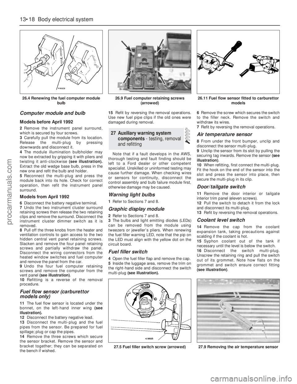
4The module illumination bulbholder may
now be extracted by gripping it with pliers and
twisting it anti-clockwise (see illustration).
Extract the old wedge base bulb, press in the
new one and refit the bulb and holder.
5Reconnect the multi-plug and press the
module back into its hole. Check for correct
operation, then refit the instrument panel
surround.
Models from April 1992
6Disconnect the battery negative terminal.
7Undo the two instrument cluster surround
retaining screws then release the two retaining
clips and remove the surround. Disconnect the
instrument cluster dimmer switch as it is
removed.
8Pull off the three knobs from the heater and
ventilation controls to gain access to the two
hidden central vent panel retaining screws.
Slacken and remove the four panel retaining
screws and partially withdraw the panel.
Disconnect the wiring connectors from the
heated window switches and fuel computer
and remove the panel from the car.
9Undo the four fuel computer retaining
screws and remove the computer from the
vent panel (see illustration).
10Refitting is a reverse of the removal
procedure.
Fuel flow sensor (carburettor
models only)
11The fuel flow sensor is located under the
bonnet, on the left-hand inner wing (see
illustration).
12Disconnect the battery negative lead.
13Disconnect the multi-plug and the fuel
pipes from the sensor. Be prepared for fuel
spillage; plug or cap the pipes.
14Remove the three screws which secure
the sensor bracket. Remove the sensor and
bracket together; they can be separated on
the bench if wished.15Refit by reversing the removal operations.
Use new fuel pipe clips if the old ones were
damaged during removal.
Note that if a fault develops in the AWS,
thorough testing and fault finding should be
left to a Ford dealer or other competent
specialist. Unskilled or uninformed testing may
cause further damage. When checking wires
or sensors for continuity, disconnect the
control assembly and bulb failure module first,
otherwise damage may be caused.
Warning light bulbs
1Refer to Sections 7 and 8.
Graphic display module
2Refer to Sections 7 and 8.
3The bulbs and light emitting diodes (LEDs)
can be removed from the module using
tweezers or jeweller’s pliers. When renewing
the fuel filler warning LED, note that the pip on
the LED must align with the yellow dot on the
circuit board.
Fuel filler switch
4Open the fuel filler flap and remove the cap.
5Inside the luggage area, remove the trim on
the right-hand side and disconnect the switch
multi-plug(see illustration).6Remove the screw which secures the switch
to the filler neck. Remove the switch and
withdraw its wires.
7Refit by reversing the removal operations.
Air temperature sensor
8From under the front bumper, unclip and
disconnect the sensor multi-plug.
9Unclip the sensor from its slot by pulling the
securing tag inwards. Remove the sensor (see
illustration).
10When refitting, first connect the multi-plug.
Fit the hook on the end of the sensor into the
slot and press the sensor into place, then
secure the multi-plug in its clip.
Door/tailgate switch
11Remove the door interior ortailgate
interior trim panel (eleven screws).
12Pull the switch to detach it from the lock
and disconnect its multi-plug.
13Refit by reversing the removal operations.
Coolant level switch
14Remove the cap from the coolant
expansion tank, taking precautions against
scalding if the coolant is hot.
15Syphon coolant out of the tank if
necessary until the level is below the switch.
16Disconnect the switch multi-plug.
Unscrew the retaining ring and pull the switch
out of its grommet. Note how flats on the
grommet and switch ensure correct fitting
(see illustration).
27Auxiliary warning system
components - testing, removal
and refitting
13•18Body electrical system
26.4 Renewing the fuel computer module
bulb
27.5 Fuel filler switch screw (arrowed)27.9 Removing the air temperature sensor
26.9 Fuel computer retaining screws
(arrowed)26.11 Fuel flow sensor fitted to carburettor
models
procarmanuals.com