1985 FORD GRANADA fuel cap release
[x] Cancel search: fuel cap releasePage 91 of 255
panel. Disconnect the wiring connectors from
the heated window switches and fuel
computer (where fitted) and remove the panel
from the car.
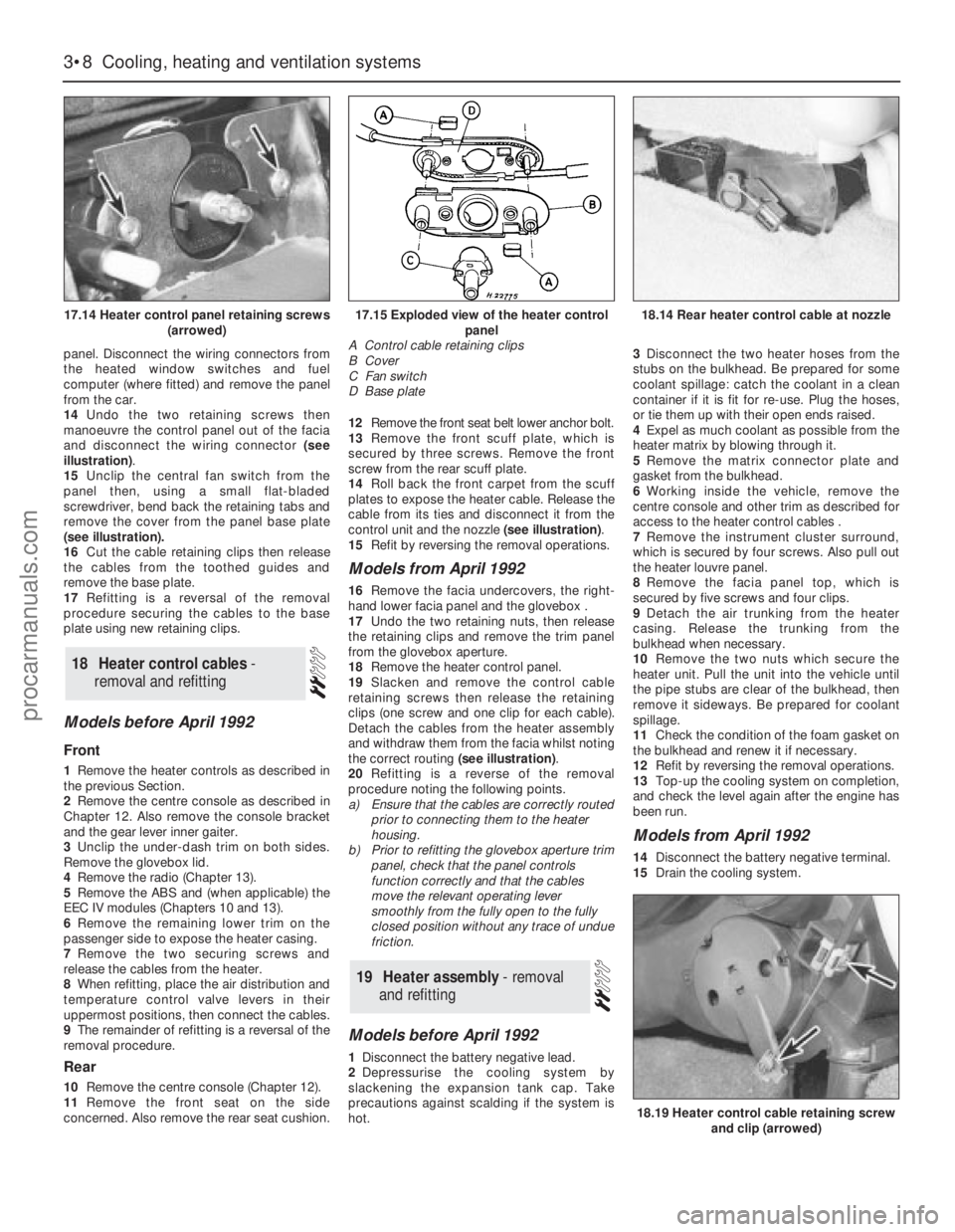
14Undo the two retaining screws then
manoeuvre the control panel out of the facia
and disconnect the wiring connector (see
illustration).
15Unclip the central fan switch from the
panel then, using a small flat-bladed
screwdriver, bend back the retaining tabs and
remove the cover from the panel base plate
(see illustration).
16Cut the cable retaining clips then release
the cables from the toothed guides and
remove the base plate.
17Refitting is a reversal of the removal
procedure securing the cables to the base
plate using new retaining clips.
Models before April 1992
Front
1Remove the heater controls as described in
the previous Section.
2Remove the centre console as described in
Chapter 12. Also remove the console bracket
and the gear lever inner gaiter.
3Unclip the under-dash trim on both sides.
Remove the glovebox lid.
4Remove the radio (Chapter 13).
5Remove the ABS and (when applicable) the
EEC IV modules (Chapters 10 and 13).
6Remove the remaining lower trim on the
passenger side to expose the heater casing.
7Remove the two securing screws and
release the cables from the heater.
8When refitting, place the air distribution and
temperature control valve levers in their
uppermost positions, then connect the cables.
9The remainder of refitting is a reversal of the
removal procedure.
Rear
10Remove the centre console (Chapter 12).
11Remove the front seat on the side
concerned. Also remove the rear seat cushion. 12Remove the front seat belt lower anchor bolt.
13Remove the front scuff plate, which is
secured by three screws. Remove the front
screw from the rear scuff plate.
14Roll back the front carpet from the scuff
plates to expose the heater cable. Release the
cable from its ties and disconnect it from the
control unit and the nozzle (see illustration).
15Refit by reversing the removal operations.
Models from April 1992
16Remove the facia undercovers, the right-
hand lower facia panel and the glovebox .
17Undo the two retaining nuts, then release
the retaining clips and remove the trim panel
from the glovebox aperture.
18Remove the heater control panel.
19Slacken and remove the control cable
retaining screws then release the retaining
clips (one screw and one clip for each cable).
Detach the cables from the heater assembly
and withdraw them from the facia whilst noting
the correct routing (see illustration).
20Refitting is a reverse of the removal
procedure noting the following points.
a)Ensure that the cables are correctly routed
prior to connecting them to the heater
housing.
b)Prior to refitting the glovebox aperture trim
panel, check that the panel controls
function correctly and that the cables
move the relevant operating lever
smoothly from the fully open to the fully
closed position without any trace of undue
friction.
Models before April 1992
1Disconnect the battery negative lead.
2Depressurise the cooling system by
slackening the expansion tank cap. Take
precautions against scalding if the system is
hot.3Disconnect the two heater hoses from the
stubs on the bulkhead. Be prepared for some
coolant spillage: catch the coolant in a clean
container if it is fit for re-use. Plug the hoses,
or tie them up with their open ends raised.
4Expel as much coolant as possible from the
heater matrix by blowing through it.
5Remove the matrix connector plate and
gasket from the bulkhead.
6Working inside the vehicle, remove the
centre console and other trim as described for
access to the heater control cables .
7Remove the instrument cluster surround,
which is secured by four screws. Also pull out
the heater louvre panel.
8Remove the facia panel top, which is
secured by five screws and four clips.
9Detach the air trunking from the heater
casing. Release the trunking from the
bulkhead when necessary.
10Remove the two nuts which secure the
heater unit. Pull the unit into the vehicle until
the pipe stubs are clear of the bulkhead, then
remove it sideways. Be prepared for coolant
spillage.
11Check the condition of the foam gasket on
the bulkhead and renew it if necessary.
12Refit by reversing the removal operations.
13Top-up the cooling system on completion,
and check the level again after the engine has
been run.
Models from April 1992
14Disconnect the battery negative terminal.
15Drain the cooling system.
19Heater assembly - removal
and refitting
18Heater control cables -
removal and refitting
3•8Cooling, heating and ventilation systems
17.14 Heater control panel retaining screws
(arrowed)
18.19 Heater control cable retaining screw
and clip (arrowed)
17.15 Exploded view of the heater control
panel
A Control cable retaining clips
B Cover
C Fan switch
D Base plate18.14 Rear heater control cable at nozzle
procarmanuals.com
Page 97 of 255
The exhaust system fitted in production is
made of aluminised steel, with stainless steel
used in the endplates and baffles of the rear
silencer. Individual sections of the system are
easily renewed in service.
Emission control for the UK market is
achieved largely by the inherent efficiency of
the fuel, ignition and engine management
systems. A welcome spin-off from such
efficiency is remarkably good fuel economy for
a vehicle of such size and weight.
Precautions
Fuel
Many of the procedures in this Chapter
require the removal of fuel lines and
connections which may result in some fuel
spillage. Residual pressure in fuel-injection
systems will remain in the fuel lines long after
the vehicle was last used, therefore extra care
must be taken when disconnecting a fuel line
hose. Loosen any fuel hose slowly to avoid a
sudden release of pressure which may cause
fuel spray. As an added precaution place a rag
over each union as it is disconnected to catch
any fuel which is forcibly expelled. Before
carrying out any operation on the fuel system
refer to the precautions given in “Safety first!”
at the beginning of this Manual and follow
them implicitly. Petrol is a highly dangerous
and volatile liquid and the precautions
necessary when handling it cannot be
overstressed
Tamperproof adjustment screws
Certain adjustment points in the fuel system
(and elsewhere) are protected by tamperproof
caps, plugs or seals. The purpose of such
tamperproofing is to discourage, and to deter,
adjustment by unqualified operators.
In some EU countries (though not yet in the
UK) it is an offence to drive a vehicle with
missing or broken tamperproof seals. Before
disturbing a tamperproof seal, satisfy yourself
that you will not be breaking local or national
anti-pollution regulations by doing so. Fit a
new seal when adjustment is complete when
this is required by law.
Do not break tamperproof seals on a vehicle
which is still under warranty.
Catalytic converter
The catalytic converter is a reliable and
simple device which needs no maintenance in
itself, but there are some facts of which an
owner should be aware if the converter is to
function properly for the full service life.
a)DO NOT use leaded petrol in a car
equipped with a catalytic converter the
lead will coat the precious metals,
reducing their converting efficiency and
will eventually destroy the converter.
b)Always keep the ignition and fuel systems
well-maintained in accordance with the
manufacturer’s schedule - particularly,
ensure that the air cleaner filter element,
the fuel filter and the spark plugs are
renewed at the correct interval - if the inletair/fuel mixture is allowed to become too
rich due to neglect, the unburned surplus
will enter and burn in the catalytic
converter, overheating the element and
eventually destroying the converter.
c)If the engine develops a misfire, do not
drive the car at all (or at least as little as
possible) until the fault is cured - the
misfire will allow unburned fuel to enter
the converter, which will result in
overheating, as noted above.
d)DO NOT push- or tow-start the car - this
will soak the catalytic converter in
unburned fuel, causing it to overheat when
the engine does start - see b) above.
e)DO NOT switch off the ignition at high
engine speeds - if the ignition is switched
off at anything above idle speed,
unburnedfuel will enter the (very hot)
catalytic converter, with the possible risk
of igniting on the element and damaging
the converter.
f)DO NOT use fuel or engine oil additives -
these may contain substances harmful to
the catalytic converter.
g)DO NOT continue to use the car if the
engine burns oil to the extent of leaving a
visible trail of blue smoke - the unburned
carbon deposits will clog the converter
passages and reduce the efficiency; in
severe cases the element will overheat.
h)Remember that the catalytic converter
operates at very high temperatures -
hence the heat shields on the car’s
underbody and the casing will become hot
enough to ignite combustible materials
which brush against it - DO NOT,
therefore, park the car in dry undergrowth,
over long grass or piles of dead leaves.
i)Remember that the catalytic converter is
FRAGILE, do not strike it with tools during
servicing work, take great care when
working on the exhaust system, ensure
that the converter is well clear of any jacks
or other lifting gear used to raise the car
and do not drive the car over rough
ground, road humps, etc, in such a way as
to “ground” the exhaust system.
j)In some cases, particularly when the car is
new and/or is used for stop/start driving, a
sulphurous smell (like that of rotten eggs)may be noticed from the exhaust. This is
common to many catalytic converter-
equipped cars and seems to be due to the
small amount of sulphur found in some
petrols reacting with hydrogen in the
exhaust to produce hydrogen sulphide
(H
2S) gas; while this gas is toxic, it is not
produced in sufficient amounts to be a
problem. Once the car has covered a few
thousand miles the problem should
disappear - in the meanwhile a change of
driving style or of the brand of petrol used
may effect a solution.
k)The catalytic converter, used on a well-
maintained and well-driven car, should
last for between 50 000 and 100 000 miles
- from this point on, careful checks should
be made at all specified service intervals
of the CO level to ensure that the
converter is still operating efficiently - if
the converter is no longer effective it must
be renewed.
See Chapter 1, Section 38.
1On carburettor models only, the air cleaner
can take in both hot and cold air. Hot air is
obtained from a shroud bolted to the exhaust
manifold.
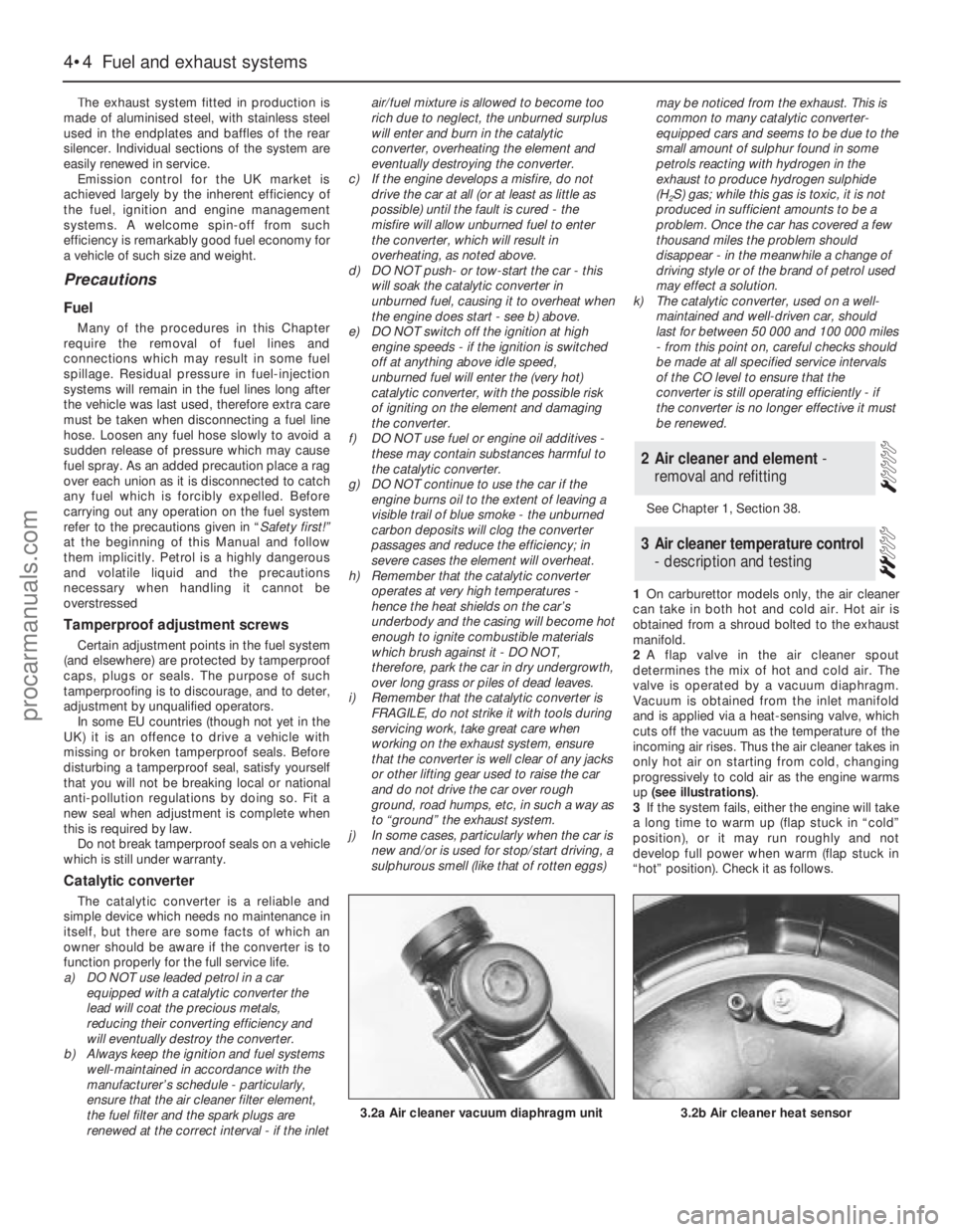
2A flap valve in the air cleaner spout
determines the mix of hot and cold air. The
valve is operated by a vacuum diaphragm.
Vacuum is obtained from the inlet manifold
and is applied via a heat-sensing valve, which
cuts off the vacuum as the temperature of the
incoming air rises. Thus the air cleaner takes in
only hot air on starting from cold, changing
progressively to cold air as the engine warms
up (see illustrations).
3If the system fails, either the engine will take
a long time to warm up (flap stuck in “cold”
position), or it may run roughly and not
develop full power when warm (flap stuck in
“hot” position). Check it as follows.
3Air cleaner temperature control
- description and testing
2Air cleaner and element -
removal and refitting
4•4Fuel and exhaust systems
3.2b Air cleaner heat sensor3.2a Air cleaner vacuum diaphragm unit
procarmanuals.com
Page 100 of 255
1Disconnect the battery negative lead.
2Disconnect the cable from the pedal.
3Working under the bonnet, free the cable
outer from the bulkhead and pull the cable into
the engine bay.
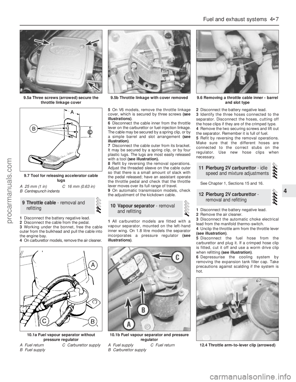
4On carburettor models, remove the air cleaner.5On V6 models, remove the throttle linkage
cover, which is secured by three screws (see
illustrations).
6Disconnect the cable inner from the throttle
lever on the carburettor or fuel-injection linkage.
The cable may be secured by a spring clip, or by
a simple barrel and slot arrangement (see
illustration).
7Disconnect the cable outer from its bracket.
It may be secured by a spring clip, or by four
plastic lugs. The lugs are most easily released
with a tool (see illustration).
8Refit by reversing the removal operations.
Adjust the threaded sleeve on the cable outer
so that there is a small amount of slack with
the pedal released; have an assistant operate
the throttle pedal and check that the throttle
lever moves over its full range of travel.
9On automatic transmission models, check
the adjustment of the kickdown cable.
1All carburettor models are fitted with a
vapour separator, mounted on the left-hand
inner wing. On 1.8 litre models the separator
incorporates a pressure regulator (see
illustrations).2Disconnect the battery negative lead.
3Identify the three hoses connected to the
separator. Disconnect the hoses, cutting off
the hose clips if they are of the crimped type.
4Remove the two securing screws and lift out
the separator. Remember it is full of fuel.
5Refit by reversing the removal operations.
Make sure that the different hoses are
connected to the correct stubs on the
regulator. Use new hose clips when
necessary.
See Chapter 1, Sections 15 and 16.
1Disconnect the battery negative lead.
2Remove the air cleaner.
3Disconnect the automatic choke electrical
lead from the manifold thermo-switch.
4Unclip the throttle arm from the throttle lever
(see illustration).
5Disconnect the fuel hose from the
carburettor and plug it. If a crimped hose clip
is fitted, cut it off and use a worm drive clip
when refitting (see illustration).
6Depressurise the cooling system by
removing the expansion tank filler cap. Take
precautions against scalding if the system is
hot.
12Pierburg 2V carburettor -
removal and refitting
11Pierburg 2V carburettor - idle
speed and mixture adjustments
10Vapour separator - removal
and refitting9Throttle cable - removal and
refitting
Fuel and exhaust systems 4•7
4
9.5a Three screws (arrowed) secure the
throttle linkage cover9.5b Throttle linkage with cover removed9.6 Removing a throttle cable inner - barrel
and slot type
12.4 Throttle arm-to-lever clip (arrowed)
9.7 Tool for releasing accelerator cable
lugs
A 25 mm (1 in)
B Centrepunch indentsC 16 mm (0.63 in)
10.1a Fuel vapour separator without
pressure regulator
A Fuel return
B Fuel supplyC Carburettor supply
10.1b Fuel vapour separator and pressure
regulator
A Fuel supply
B Carburettor supplyC Fuel return
procarmanuals.com
Page 102 of 255
1Check the cost and availability of spare parts
before deciding to dismantle the carburettor. If
the unit has seen much service, fitting a new or
reconditioned carburettor may prove more
satisfactory than any attempt at overhaul.
2Obtain a carburettor repair kit, which will
contain the necessary gaskets, diaphragms
and other renewable items.
3With the carburettor removed from the
vehicle, clean it thoroughly externally and
place it on a clean worksurface.
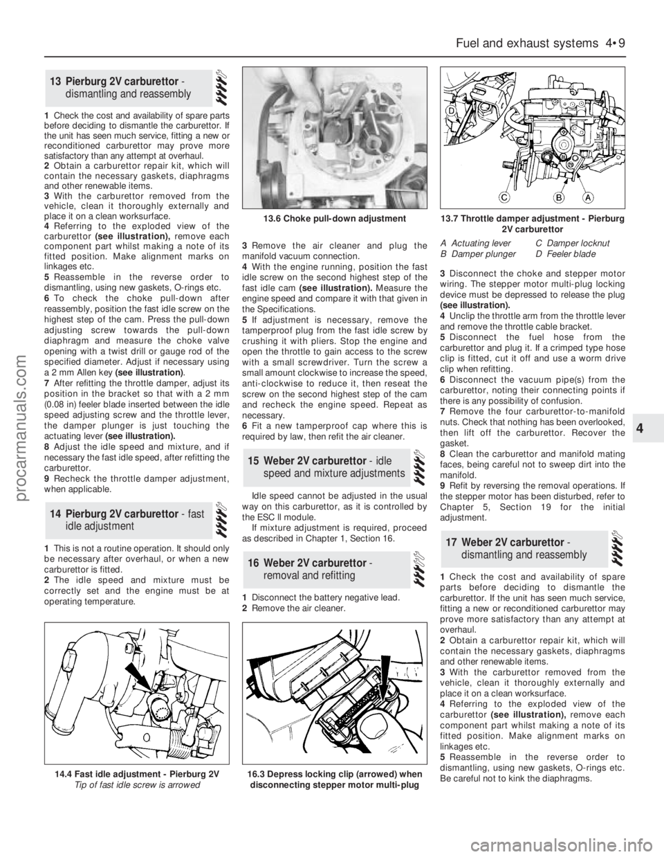
4 Referringto the exploded view of the
carburettor(see illustration),remove each
component part whilst making a note of its
fitted position. Make alignment marks on
linkages etc.
5Reassemble in the reverse order to
dismantling, using new gaskets, O-rings etc.
6To check the choke pull-down after
reassembly, position the fast idle screw on the
highest step of the cam. Press the pull-down
adjusting screw towards the pull-down
diaphragm and measure the choke valve
opening with a twist drill or gauge rod of the
specified diameter. Adjust if necessary using
a 2 mm Allen key (see illustration).
7After refitting the throttle damper, adjust its
position in the bracket so that with a 2 mm
(0.08 in) feeler blade inserted between the idle
speed adjusting screw and the throttle lever,
the damper plunger is just touching the
actuating lever(see illustration).
8Adjust the idle speed and mixture, and if
necessary the fast idle speed, after refitting the
carburettor.
9Recheck the throttle damper adjustment,
when applicable.
1This is not a routine operation. It should only
be necessary after overhaul, or when a new
carburettor is fitted.
2The idle speed and mixture must be
correctly set and the engine must be at
operating temperature.3Remove the air cleaner and plug the
manifold vacuum connection.
4With the engine running, position the fast
idle screw on the second highest step of the
fast idle cam(see illustration).Measure the
engine speed and compare it with that given in
the Specifications.
5If adjustment is necessary, remove the
tamperproof plug from the fast idle screw by
crushing it with pliers. Stop the engine and
open the throttle to gain access to the screw
with a small screwdriver. Turn the screw a
small amount clockwise to increase the speed,
anti-clockwise to reduce it, then reseat the
screw on the second highest step of the cam
and recheck the engine speed. Repeat as
necessary.
6Fit a new tamperproof cap where this is
required by law, then refit the air cleaner.
Idle speed cannot be adjusted in the usual
way on this carburettor, as it is controlled by
the ESC ll module.
If mixture adjustment is required, proceed
as described in Chapter 1, Section 16.
1Disconnect the battery negative lead.
2Remove the air cleaner.3Disconnect the choke and stepper motor
wiring. The stepper motor multi-plug locking
device must be depressed to release the plug
(seeillustration).
4Unclip the throttle arm from the throttle lever
and remove the throttle cable bracket.
5Disconnect the fuel hose from the
carburettor and plug it. If a crimped type hose
clip is fitted, cut it off and use a worm drive
clip when refitting.
6Disconnect the vacuum pipe(s) from the
carburettor, noting their connecting points if
there is any possibility of confusion.
7Remove the four carburettor-to-manifold
nuts. Check that nothing has been overlooked,
then lift off the carburettor. Recover the
gasket.
8Clean the carburettor and manifold mating
faces, being careful not to sweep dirt into the
manifold.
9Refit by reversing the removal operations. If
the stepper motor has been disturbed, refer to
Chapter 5, Section 19 for the initial
adjustment.
1Check the cost and availability of spare
parts before deciding to dismantle the
carburettor. If the unit has seen much service,
fitting a new or reconditioned carburettor may
prove more satisfactory than any attempt at
overhaul.
2Obtain a carburettor repair kit, which will
contain the necessary gaskets, diaphragms
and other renewable items.
3With the carburettor removed from the
vehicle, clean it thoroughly externally and
place it on a clean worksurface.
4 Referringto the exploded view of the
carburettor(see illustration),remove each
component part whilst making a note of its
fitted position. Make alignment marks on
linkages etc.
5Reassemble in the reverse order to
dismantling, using new gaskets, O-rings etc.
Be careful not to kink the diaphragms.
17Weber 2V carburettor -
dismantling and reassembly
16Weber 2V carburettor -
removal and refitting
15Weber 2V carburettor - idle
speed and mixture adjustments
14Pierburg 2V carburettor - fast
idle adjustment
13Pierburg 2V carburettor -
dismantling and reassembly
Fuel and exhaust systems 4•9
4
14.4 Fast idle adjustment - Pierburg 2V
Tip of fast idle screw is arrowed
13.6 Choke pull-down adjustment13.7 Throttle damper adjustment - Pierburg
2V carburettor
A Actuating lever
B Damper plungerC Damper locknut
D Feeler blade
16.3 Depress locking clip (arrowed) when
disconnecting stepper motor multi-plug
procarmanuals.com
Page 107 of 255
16Start the engine and note the engine
speed (rpm). The engine speed should
increase above the normal idle speed, and
should be as given in the Specifications.
17If the engine speed is not as specified,
remove the tamperproof plug from the top of
the throttle kicker housing, and turn the
adjustment screw to give the specified speed.
18On completion of adjustment, fit a new
tamperproof cap.
19Disconnect the tubing from the inlet
manifold, and reconnect the throttle kicker
vacuum hose.
20Refit the plastic shield and the air cleaner.
On 2.4 & 2.9 litre V6 models especially,
residual pressure will remain in the fuel lines
long after the vehicle was last used therefore
the fuel system must be depressurised before
any hose is disconnected; the system is
depressurised via the vent valve on the fuel
rail, noting that it may be necessary to depress
the valve several times before the pressure is
fully released. As an added precaution place a
rag over the valve as it is depressed to catch
any fuel which is forcibly expelled. Before
carrying out any operation on the fuel system
refer to the precautions given in Safety first! at
the beginning of this Manual and follow them
implicitly. Petrol is a highly dangerous and
volatile liquid and the precautions necessary
when handling it cannot be overstressed.
Access to the relays is obtained by
removing the facia top cover (crash pad).
The relays are located on the passenger
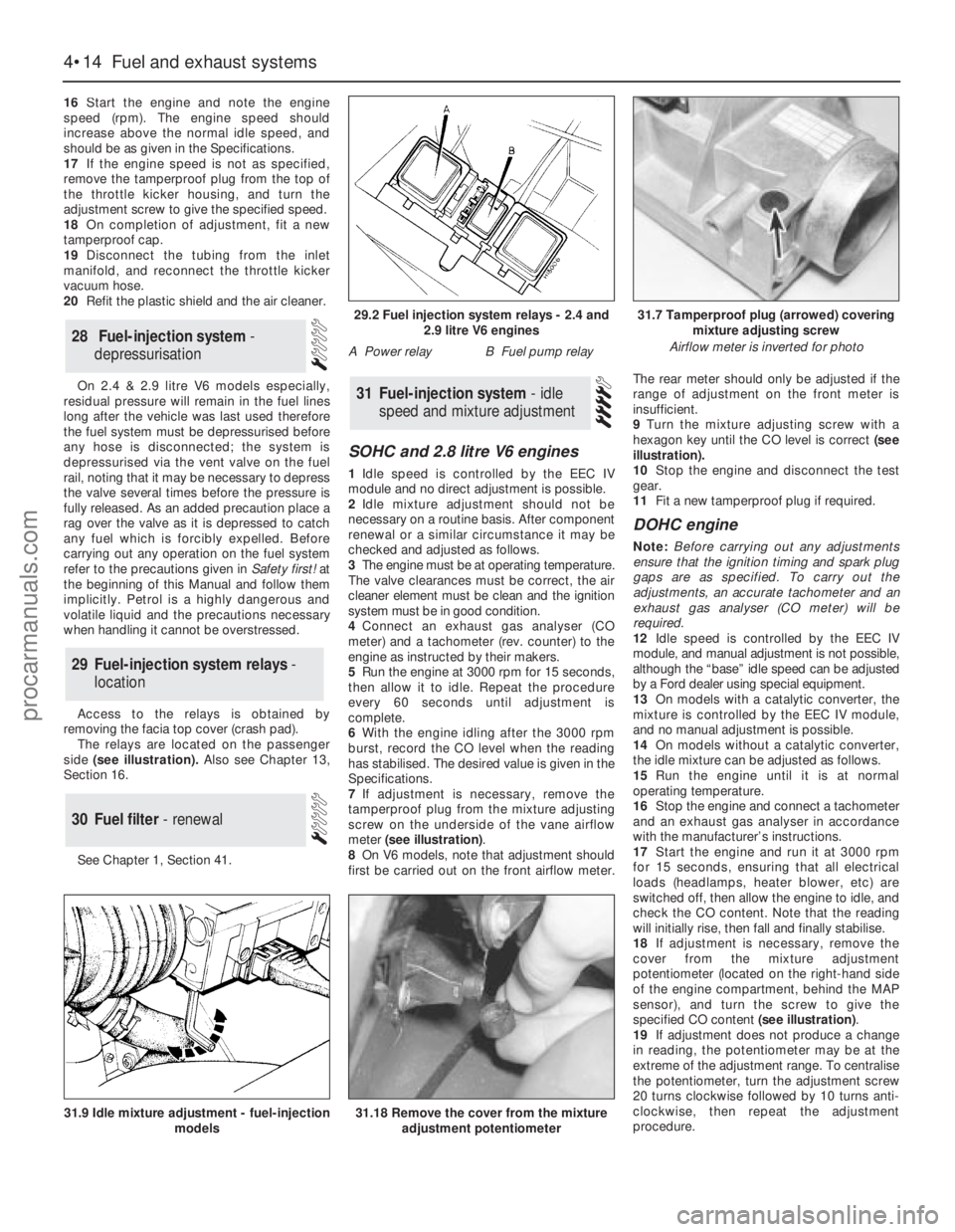
side(see illustration). Also see Chapter 13,
Section 16.
See Chapter 1, Section 41.
SOHC and 2.8 litre V6 engines
1Idle speed is controlled by the EEC IV
module and no direct adjustment is possible.
2Idle mixture adjustment should not be
necessary on a routine basis. After component
renewal or a similar circumstance it may be
checked and adjusted as follows.
3The engine must be at operating temperature.
The valve clearances must be correct, the air
cleaner element must be clean and the ignition
system must be in good condition.
4Connect an exhaust gas analyser (CO
meter) and a tachometer (rev. counter) to the
engine as instructed by their makers.
5Run the engine at 3000 rpm for 15 seconds,
then allow it to idle. Repeat the procedure
every 60 seconds until adjustment is
complete.
6With the engine idling after the 3000 rpm
burst, record the CO level when the reading
has stabilised. The desired value is given in the
Specifications.
7If adjustment is necessary, remove the
tamperproof plug from the mixture adjusting
screw on the underside of the vane airflow
meter (see illustration).
8On V6 models, note that adjustment should
first be carried out on the front airflow meter.The rear meter should only be adjusted if the
range of adjustment on the front meter is
insufficient.
9Turn the mixture adjusting screw with a
hexagon key until the CO level is correct (see
illustration).
10Stop the engine and disconnect the test
gear.
11Fit a new tamperproof plug if required.
DOHC engine
Note: Before carrying out any adjustments
ensure that the ignition timing and spark plug
gaps are as specified. To carry out the
adjustments, an accurate tachometer and an
exhaust gas analyser (CO meter) will be
required.
12Idle speed is controlled by the EEC IV
module, and manual adjustment is not possible,
although the “base” idle speed can be adjusted
by a Ford dealer using special equipment.
13On models with a catalytic converter, the
mixture is controlled by the EEC IV module,
and no manual adjustment is possible.
14On models without a catalytic converter,
the idle mixture can be adjusted as follows.
15Run the engine until it is at normal
operating temperature.
16Stop the engine and connect a tachometer
and an exhaust gas analyser in accordance
with the manufacturer’s instructions.
17Start the engine and run it at 3000 rpm
for 15 seconds, ensuring that all electrical
loads (headlamps, heater blower, etc) are
switched off, then allow the engine to idle, and
check the CO content. Note that the reading
will initially rise, then fall and finally stabilise.
18If adjustment is necessary, remove the
cover from the mixture adjustment
potentiometer (located on the right-hand side
of the engine compartment, behind the MAP
sensor), and turn the screw to give the
specified CO content (see illustration).
19If adjustment does not produce a change
in reading, the potentiometer may be at the
extreme of the adjustment range. To centralise
the potentiometer, turn the adjustment screw
20 turns clockwise followed by 10 turns anti-
clockwise, then repeat the adjustment
procedure.
31Fuel-injection system - idle
speed and mixture adjustment
30Fuel filter - renewal
29Fuel-injection system relays -
location
28Fuel-injection system -
depressurisation
4•14Fuel and exhaust systems
31.18 Remove the cover from the mixture
adjustment potentiometer31.9 Idle mixture adjustment - fuel-injection
models
29.2 Fuel injection system relays - 2.4 and
2.9 litre V6 engines
A Power relayB Fuel pump relay
31.7 Tamperproof plug (arrowed) covering
mixture adjusting screw
Airflow meter is inverted for photo
procarmanuals.com
Page 109 of 255
9Unscrew the securing nut, and release the
air inlet tube from the bracket on the engine
compartment front panel.
10Disconnect the wiring plug from the idle
speed control valve.
11Release the air cleaner lid securing clips,
then remove the air inlet tube, plenum
chamber, and air cleaner lid as an assembly,
disconnecting the breather hose from the air
inlet tube.
12Unscrew the two securing bolts, and
withdraw the valve from the air inlet tube (see
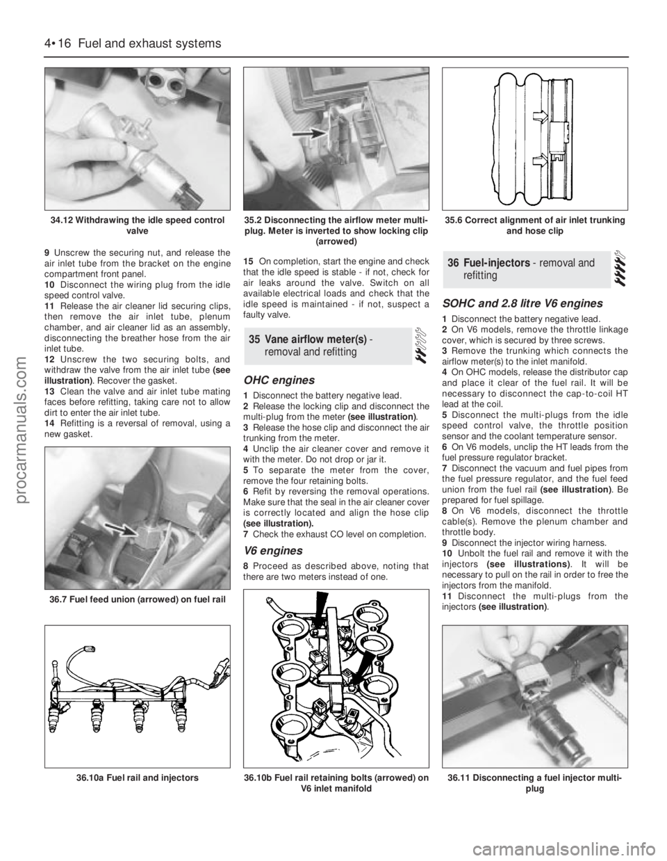
illustration). Recover the gasket.
13Clean the valve and air inlet tube mating
faces before refitting, taking care not to allow
dirt to enter the air inlet tube.
14Refitting is a reversal of removal, using a
new gasket.15On completion, start the engine and check
that the idle speed is stable - if not, check for
air leaks around the valve. Switch on all
available electrical loads and check that the
idle speed is maintained - if not, suspect a
faulty valve.
OHC engines
1Disconnect the battery negative lead.
2Release the locking clip and disconnect the
multi-plug from the meter (see illustration).
3Release the hose clip and disconnect the air
trunking from the meter.
4Unclip the air cleaner cover and remove it
with the meter. Do not drop or jar it.
5To separate the meter from the cover,
remove the four retaining bolts.
6Refit by reversing the removal operations.
Make sure that the seal in the air cleaner cover
is correctly located and align the hose clip
(seeillustration).
7Check the exhaust CO level on completion.
V6 engines
8Proceed as described above, noting that
there are two meters instead of one.
SOHC and 2.8 litre V6 engines
1Disconnect the battery negative lead.
2On V6 models, remove the throttle linkage
cover, which is secured by three screws.
3Remove the trunking which connects the
airflow meter(s) to the inlet manifold.
4On OHCmodels, release the distributor cap
and place it clear of the fuel rail. It will be
necessary to disconnect the cap-to-coil HT
lead at the coil.
5Disconnect the multi-plugs from the idle
speed control valve, the throttle position
sensor and the coolant temperature sensor.
6On V6 models, unclip the HT leads from the
fuel pressure regulator bracket.
7Disconnect the vacuum and fuel pipes from
the fuel pressure regulator, and the fuel feed
union from the fuel rail (see illustration). Be
prepared for fuel spillage.
8On V6 models, disconnect the throttle
cable(s). Remove the plenum chamber and
throttle body.
9Disconnect the injector wiring harness.
10Unbolt the fuel rail and remove it with the
injectors (see illustrations). It will be
necessary to pull on the rail in order to free the
injectors from the manifold.
11Disconnect the multi-plugs from the
injectors (see illustration).
36Fuel-injectors - removal and
refitting
35Vane airflow meter(s) -
removal and refitting
4•16Fuel and exhaust systems
34.12 Withdrawing the idle speed control
valve
36.7 Fuel feed union (arrowed) on fuel rail
36.10a Fuel rail and injectors36.10b Fuel rail retaining bolts (arrowed) on
V6 inlet manifold36.11 Disconnecting a fuel injector multi-
plug
35.2 Disconnecting the airflow meter multi-
plug. Meter is inverted to show locking clip
(arrowed)35.6 Correct alignment of air inlet trunking
and hose clip
procarmanuals.com
Page 170 of 255
6Disconnect the glovebox arms and hinges.
Withdraw the hinge pins and remove the lid.
7Slide the auxiliary fuse panel off its
mounting and remove the glovebox light
(when fitted).
8Remove the ABS and ESC/EEC modules
(Chapter 13). Remove the two nuts and
washers from inside the glovebox.
9Remove the radio, stowage box or graphic
equaliser, ashtray, cigarette lighter panel and
(when applicable) the gear lever gaiter.
10Remove the centre console, disconnecting
switches, rear heater controls etc as
necessary.
11Remove the six screws which secure the
passenger’s side lower panel. Remove the
panel. 12Refit by reversing the removal operations,
transferring the brackets, captive nuts or other
fittings to any new panels being fitted.
Models from April 1992
13Disconnect the battery negative terminal.
14Remove the centre console.
15Remove the radio, amplifier unit and
(where necessary) the CD player.
16Remove the instrument cluster.
17Remove the steering wheel and then the
steering column direction indicator/headlight
flasher switch and windscreen wipe/wash
switch.
18Pull off the three knobs from the heater
and ventilation controls to gain access to the
two hidden central vent panel retainingscrews. Slacken and remove the four panel
retaining screws and partially withdraw the
panel. Disconnect the wiring connectors from
the heated window switches and fuel
computer (where fitted) and remove the panel
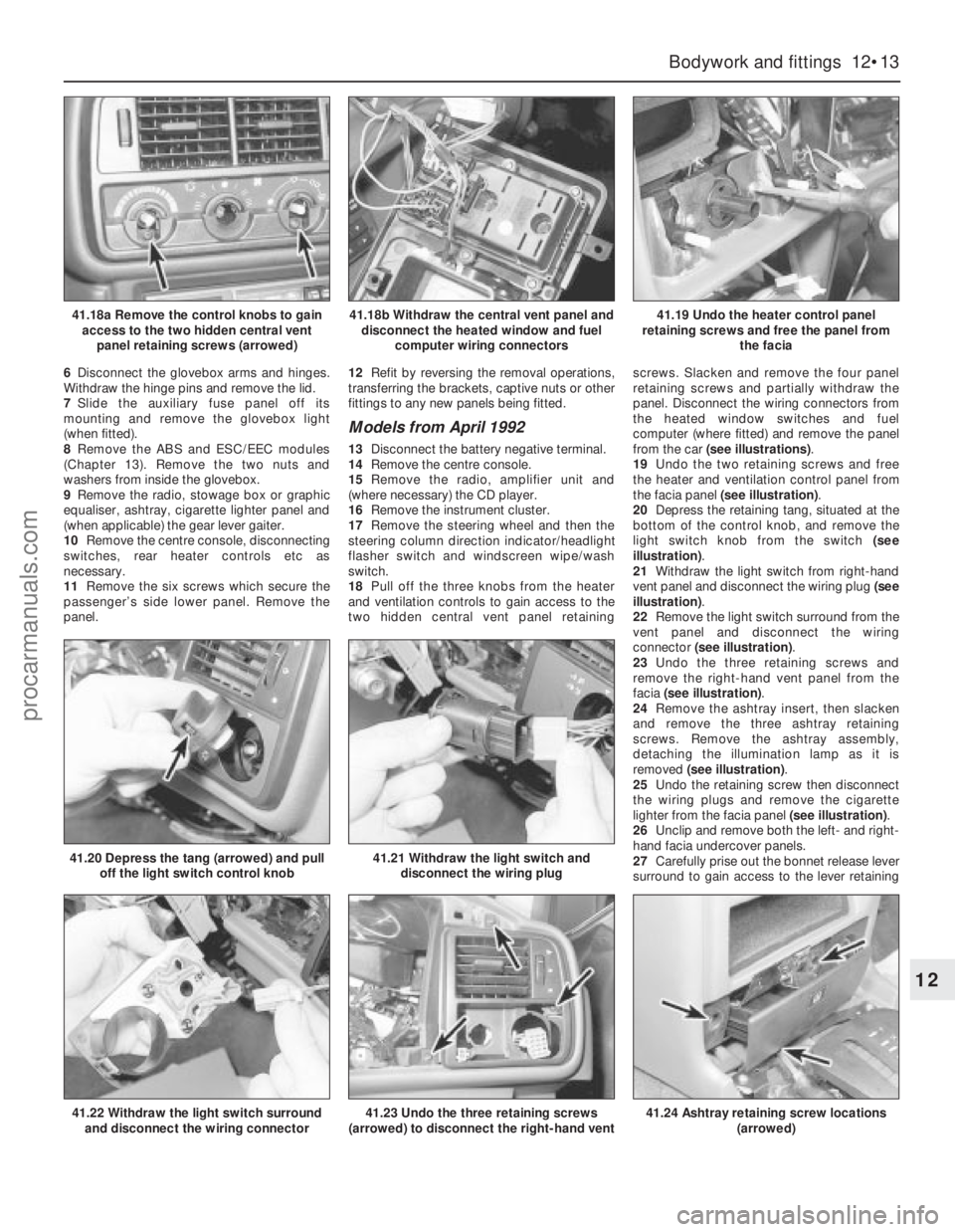
from the car (see illustrations).
19Undo the two retaining screws and free
the heater and ventilation control panel from
the facia panel (see illustration).
20Depress the retaining tang, situated at the
bottom of the control knob, and remove the
light switch knob from the switch (see
illustration).
21Withdraw the light switch from right-hand
vent panel and disconnect the wiring plug (see
illustration).
22Remove the light switch surround from the
vent panel and disconnect the wiring
connector (see illustration).
23Undo the three retaining screws and
remove the right-hand vent panel from the
facia (see illustration).
24Remove the ashtray insert, then slacken
and remove the three ashtray retaining
screws. Remove the ashtray assembly,
detaching the illumination lamp as it is
removed (see illustration).
25Undo the retaining screw then disconnect
the wiring plugs and remove the cigarette
lighter from the facia panel (see illustration).
26Unclip and remove both the left- and right-
hand facia undercover panels.
27Carefully prise out the bonnet release lever
surround to gain access to the lever retaining
Bodywork and fittings 12•13
12
41.18a Remove the control knobs to gain
access to the two hidden central vent
panel retaining screws (arrowed)41.18b Withdraw the central vent panel and
disconnect the heated window and fuel
computer wiring connectors41.19 Undo the heater control panel
retaining screws and free the panel from
the facia
41.22 Withdraw the light switch surround
and disconnect the wiring connector
41.20 Depress the tang (arrowed) and pull
off the light switch control knob41.21 Withdraw the light switch and
disconnect the wiring plug
41.23 Undo the three retaining screws
(arrowed) to disconnect the right-hand vent41.24 Ashtray retaining screw locations
(arrowed)
procarmanuals.com
Page 195 of 255
Computer module and bulb
Models before April 1992
2Remove the instrument panel surround,
which is secured by four screws.
3Carefully pull the module from its location.
Release the multi-plug by pressing
downwards and disconnect it.
4The module illumination bulbholder may
now be extracted by gripping it with pliers and
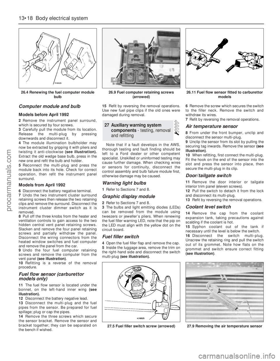
twisting it anti-clockwise (see illustration).
Extract the old wedge base bulb, press in the
new one and refit the bulb and holder.
5Reconnect the multi-plug and press the
module back into its hole. Check for correct
operation, then refit the instrument panel
surround.
Models from April 1992
6Disconnect the battery negative terminal.
7Undo the two instrument cluster surround
retaining screws then release the two retaining
clips and remove the surround. Disconnect the
instrument cluster dimmer switch as it is
removed.
8Pull off the three knobs from the heater and
ventilation controls to gain access to the two
hidden central vent panel retaining screws.
Slacken and remove the four panel retaining
screws and partially withdraw the panel.
Disconnect the wiring connectors from the
heated window switches and fuel computer
and remove the panel from the car.
9Undo the four fuel computer retaining
screws and remove the computer from the
vent panel (see illustration).
10Refitting is a reverse of the removal
procedure.
Fuel flow sensor (carburettor
models only)
11The fuel flow sensor is located under the
bonnet, on the left-hand inner wing (see
illustration).
12Disconnect the battery negative lead.
13Disconnect the multi-plug and the fuel
pipes from the sensor. Be prepared for fuel
spillage; plug or cap the pipes.
14Remove the three screws which secure
the sensor bracket. Remove the sensor and
bracket together; they can be separated on
the bench if wished.15Refit by reversing the removal operations.
Use new fuel pipe clips if the old ones were
damaged during removal.
Note that if a fault develops in the AWS,
thorough testing and fault finding should be
left to a Ford dealer or other competent
specialist. Unskilled or uninformed testing may
cause further damage. When checking wires
or sensors for continuity, disconnect the
control assembly and bulb failure module first,
otherwise damage may be caused.
Warning light bulbs
1Refer to Sections 7 and 8.
Graphic display module
2Refer to Sections 7 and 8.
3The bulbs and light emitting diodes (LEDs)
can be removed from the module using
tweezers or jeweller’s pliers. When renewing
the fuel filler warning LED, note that the pip on
the LED must align with the yellow dot on the
circuit board.
Fuel filler switch
4Open the fuel filler flap and remove the cap.
5Inside the luggage area, remove the trim on
the right-hand side and disconnect the switch
multi-plug(see illustration).6Remove the screw which secures the switch
to the filler neck. Remove the switch and
withdraw its wires.
7Refit by reversing the removal operations.
Air temperature sensor
8From under the front bumper, unclip and
disconnect the sensor multi-plug.
9Unclip the sensor from its slot by pulling the
securing tag inwards. Remove the sensor (see
illustration).
10When refitting, first connect the multi-plug.
Fit the hook on the end of the sensor into the
slot and press the sensor into place, then
secure the multi-plug in its clip.
Door/tailgate switch
11Remove the door interior ortailgate
interior trim panel (eleven screws).
12Pull the switch to detach it from the lock
and disconnect its multi-plug.
13Refit by reversing the removal operations.
Coolant level switch
14Remove the cap from the coolant
expansion tank, taking precautions against
scalding if the coolant is hot.
15Syphon coolant out of the tank if
necessary until the level is below the switch.
16Disconnect the switch multi-plug.
Unscrew the retaining ring and pull the switch
out of its grommet. Note how flats on the
grommet and switch ensure correct fitting
(see illustration).
27Auxiliary warning system
components - testing, removal
and refitting
13•18Body electrical system
26.4 Renewing the fuel computer module
bulb
27.5 Fuel filler switch screw (arrowed)27.9 Removing the air temperature sensor
26.9 Fuel computer retaining screws
(arrowed)26.11 Fuel flow sensor fitted to carburettor
models
procarmanuals.com