1985 FORD GRANADA check transmission fluid
[x] Cancel search: check transmission fluidPage 43 of 255
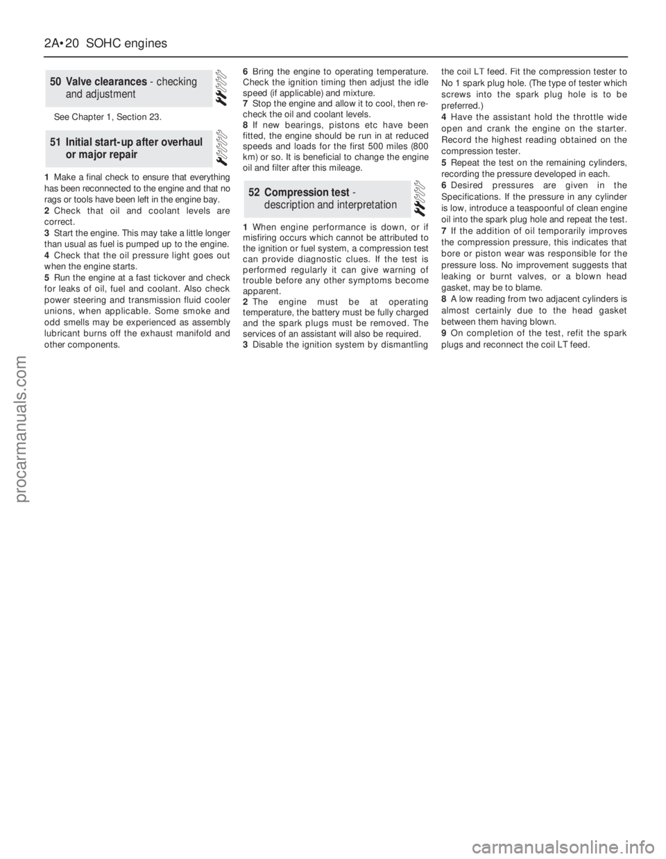
See Chapter 1, Section 23.
1Make a final check to ensure that everything
has been reconnected to the engine and that no
rags or tools have been left in the engine bay.
2Check that oil and coolant levels are
correct.
3Start the engine. This may take a little longer
than usual as fuel is pumped up to the engine.
4Check that the oil pressure light goes out
when the engine starts.
5Run the engine at a fast tickover and check
for leaks of oil, fuel and coolant. Also check
power steering and transmission fluid cooler
unions, when applicable. Some smoke and
odd smells may be experienced as assembly
lubricant burns off the exhaust manifold and
other components.6Bring the engine to operating temperature.
Check the ignition timing then adjust the idle
speed (if applicable) and mixture.
7Stop the engine and allow it to cool, then re-
check the oil and coolant levels.
8If new bearings, pistons etc have been
fitted, the engine should be run in at reduced
speeds and loads for the first 500 miles (800
km) or so. It is beneficial to change the engine
oil and filter after this mileage.
1When engine performance is down, or if
misfiring occurs which cannot be attributed to
the ignition or fuel system, a compression test
can provide diagnostic clues. If the test is
performed regularly it can give warning of
trouble before any other symptoms become
apparent.
2The engine must be at operating
temperature, the battery must be fully charged
and the spark plugs must be removed. The
services of an assistant will also be required.
3Disable the ignition system by dismantlingthe coil LT feed. Fit the compression tester to
No 1 spark plug hole. (The type of tester which
screws into the spark plug hole is to be
preferred.)
4Have the assistant hold the throttle wide
open and crank the engine on the starter.
Record the highest reading obtained on the
compression tester.
5Repeat the test on the remaining cylinders,
recording the pressure developed in each.
6Desired pressures are given in the
Specifications. If the pressure in any cylinder
is low, introduce a teaspoonful of clean engine
oil into the spark plug hole and repeat the test.
7If the addition of oil temporarily improves
the compression pressure, this indicates that
bore or piston wear was responsible for the
pressure loss. No improvement suggests that
leaking or burnt valves, or a blown head
gasket, may be to blame.
8A low reading from two adjacent cylinders is
almost certainly due to the head gasket
between them having blown.
9On completion of the test, refit the spark
plugs and reconnect the coil LT feed.
52Compression test -
description and interpretation
51Initial start-up after overhaul
or major repair
50Valve clearances - checking
and adjustment
2A•20SOHCengines
procarmanuals.com
Page 48 of 255
27Remove the starter motor.
28Remove the exhaust downpipe.
29Ensure that the steering wheel is
positioned in the straight-ahead position then,
using a dab of paint or a suitable marker pen,
make alignment marks between the
intermediate shaft lower clamp and steering
gear pinion. Slacken and remove the lower
clamp bolt then disconnect the intermediate
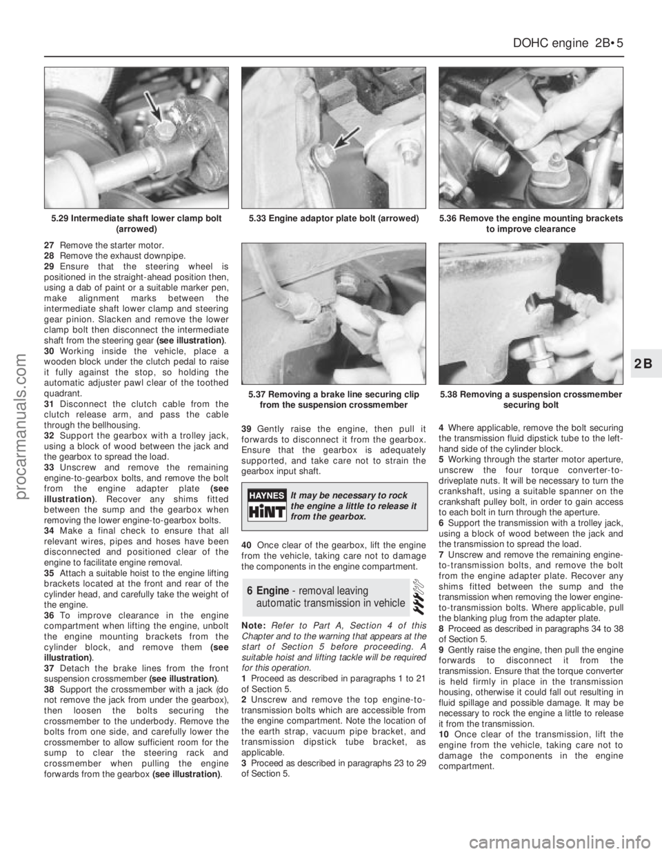
shaft from the steering gear (see illustration).
30Working inside the vehicle, place a
wooden block under the clutch pedal to raise
it fully against the stop, so holding the
automatic adjuster pawl clear of the toothed
quadrant.
31Disconnect the clutch cable from the
clutch release arm, and pass the cable
through the bellhousing.
32Support the gearbox with a trolley jack,
using a block of wood between the jack and
the gearbox to spread the load.
33Unscrew and remove the remaining
engine-to-gearbox bolts, and remove the bolt
from the engine adapter plate (see
illustration). Recover any shims fitted
between the sump and the gearbox when
removing the lower engine-to-gearbox bolts.
34Make a final check to ensure that all
relevant wires, pipes and hoses have been
disconnected and positioned clear of the
engine to facilitate engine removal.
35Attach a suitable hoist to the engine lifting
brackets located at the front and rear of the
cylinder head, and carefully take the weight of
the engine.
36To improve clearance in the engine
compartment when lifting the engine, unbolt
the engine mounting brackets from the
cylinder block, and remove them (see
illustration).
37Detach the brake lines from the front
suspension crossmember (see illustration).
38Support the crossmember with a jack (do
not remove the jack from under the gearbox),
then loosen the bolts securing the
crossmember to the underbody. Remove the
bolts from one side, and carefully lower the
crossmember to allow sufficient room for the
sump to clear the steering rack and
crossmember when pulling the engine
forwards from the gearbox (see illustration).39Gently raise the engine, then pull it
forwards to disconnect it from the gearbox.
Ensure that the gearbox is adequately
supported, and take care not to strain the
gearbox input shaft.
40Once clear of the gearbox, lift the engine
from the vehicle, taking care not to damage
the components in the engine compartment.
Note:Refer to Part A, Section 4 of this
Chapter and to the warning that appears at the
start of Section 5 before proceeding. A
suitable hoist and lifting tackle will be required
for this operation.
1Proceed as described in paragraphs 1 to 21
of Section 5.
2Unscrew and remove the top engine-to-
transmission bolts which are accessible from
the engine compartment. Note the location of
the earth strap, vacuum pipe bracket, and
transmission dipstick tube bracket, as
applicable.
3Proceed as described in paragraphs 23 to 29
of Section 5.4Where applicable, remove the bolt securing
the transmission fluid dipstick tube to the left-
hand side of the cylinder block.
5Working through the starter motor aperture,
unscrew the four torque converter-to-
driveplate nuts. It will be necessary to turn the
crankshaft, using a suitable spanner on the
crankshaft pulley bolt, in order to gain access
to each bolt in turn through the aperture.
6Support the transmission with a trolley jack,
using a block of wood between the jack and
the transmission to spread the load.
7Unscrew and remove the remaining engine-
to-transmission bolts, and remove the bolt
from the engine adapter plate. Recover any
shims fitted between the sump and the
transmission when removing the lower engine-
to-transmission bolts. Where applicable, pull
the blanking plug from the adapter plate.
8Proceed as described in paragraphs 34 to 38
of Section 5.
9Gently raise the engine, then pull the engine
forwards to disconnect it from the
transmission. Ensure that the torque converter
is held firmly in place in the transmission
housing, otherwise it could fall out resulting in
fluid spillage and possible damage. It may be
necessary to rock the engine a little to release
it from the transmission.
10Once clear of the transmission, lift the
engine from the vehicle, taking care not to
damage the components in the engine
compartment.
6Engine - removal leaving
automatic transmission in vehicle
DOHCengine 2B•5
2B
5.29 Intermediate shaft lower clamp bolt
(arrowed)5.33 Engine adaptor plate bolt (arrowed)5.36 Remove the engine mounting brackets
to improve clearance
5.37 Removing a brake line securing clip
from the suspension crossmember5.38 Removing a suspension crossmember
securing bolt
It may be necessary to rock
the engine a little to release it
from the gearbox.
procarmanuals.com
Page 49 of 255
Note: Refer to Part A, Section 4 of this Chapter
and to the warning that appears at the start of
Section 5 before proceeding. A hoist and lifting
tackle will be required for this operation.
1Proceed as described in paragraphs 1 to 21
of Section 5.
2Unscrew the securing bolt, and disconnect
the earth lead from the rear left-hand side of
the cylinder head.
3Unscrew the nuts securing the engine
mountings to the engine mounting brackets.
4Jack up the vehicle and support it securely
on axle stands (see “Jacking”). Ensure that
there is enough working room beneath the
vehicle.
5To improve access, disconnect the exhaust
downpipe from the manifold and remove the
exhaust system.
6Drain the engine oil into a suitable container.
7On models fitted with a catalytic converter,
release the securing clips and withdraw the
exhaust heat shield from under the vehicle for
access to the propeller shaft.
8Remove the propeller shaft.
9Where applicable, bend back the locktabs,
then unscrew the two bolts in each case
securing the two anti-roll bar mounting clamps
to the vehicle underbody. Lower the anti-roll
bar as far as possible.
10Proceed as described in paragraphs 30
and 31 of Section 5.
11Support the gearbox with a trolley jack,
using a block of wood between the jack and
the gearbox to spread the load.
12Unscrew the four nuts securing the
gearbox crossmember to the vehicle
underbody. Unscrew the central bolt securing
the crossmember to the gearbox, and remove
the crossmember. Note the position of the
earth strap, where applicable. Recover the
mounting cup, and the exhaust mounting
bracket and heat shield (as applicable).
13Lower the gearbox slightly on the jack,
then remove the circlip, and disconnect the
speedometer drive cable from the gearbox.
14Disconnect the wiring from the reversing
lamp switch, and on models with fuel-injection,
disconnect the wiring from the vehicle speed
sensor mounted in the side of the gearbox.
15Slacken and remove the two bolts and
washers (one either side) securing the gear
linkage support bracket to the gearbox.
16Using a pin punch, drive out the roll pin
securing the gearchange rod to the gear linkage.
17Attach a hoist to the engine lifting brackets
located at the front and rear of the cylinder head,
and slowly take the weight of the engine. Arrange
the lifting tackle so that the engine/gearbox
assembly will assume a steep angle of
approximately 40°to 45°as it is being removed.
18To improve clearance in the engine
compartment when lifting the engine, unboltthe engine mounting brackets from the
cylinder block, and remove them.
19Ensure that the steering wheel is positioned
in the straight-ahead position then, using a dab
of paint or a marker pen, make alignment marks
between the intermediate shaft lower clamp
and steering gear pinion. Slacken and remove
the lower clamp bolt then disconnect the
intermediate shaft from the steering gear.
20Detach the brake lines from the front
suspension crossmember.
21Support the crossmember with a jack (do not
remove the jack from under the gearbox), then
loosen the bolts securing the crossmember to the
underbody. Remove the crossmember securing
bolts, and carefully lower the crossmember to
allow sufficient room for the engine sump to clear
the steering rack and crossmember as the
engine/gearbox assembly is removed.
22Make a final check to ensure that all
relevant wires, pipes and hoses have been
disconnected to facilitate removal of the
engine/gearbox assembly.
23Raise the engine/gearbox, at the same
time lowering the trolley jack which is
supporting the gearbox.
24Place a suitable rod across the vehicle
underbody to support the gear linkage support
bracket whilst the gearbox is removed.
25Tilt the engine/gearbox assembly using
the hoist and the trolley jack, until the
assembly can be lifted from the vehicle. Take
care not to damage surrounding components.
26If the vehicle is to be moved, with the
engine/gearbox assembly removed, temporarily
refit the suspension crossmember and the anti-
roll bar to the underbody, and reconnect the
steering column to the intermediate shaft.
27To separate the engine from the gearbox,
proceed as follows.
28Remove the starter motor.
29Support the engine and gearbox
horizontally on blocks of wood.
30Unscrew the engine-to-gearbox bolts,
noting the locations of the bolts, and the
positions of the earth strap and any wiring clips
attached to the bolts. Recover any shims fitted
between the sump and the gearbox when
removing the lower engine-to-gearbox bolts.
31Unscrew the bolt from the engine adapter
plate.
32Pull the engine and gearbox apart, taking
care not to strain the gearbox input shaft. It
may be necessary to rock the units slightly to
separate them.
Note: Refer to Part A, Section 4 of this
Chapter and to the warning that appears at the
start of Section 5 before proceeding. A
suitable hoist and lifting tackle will be required
for this operation. Any suspected faults in the
automatic transmission should be referred to a
Ford dealer or automatic transmissionspecialist before removal of unit, as the
specialist fault diagnosis equipment is
designed to operate with the transmission in
the vehicle.
1Proceed as described in paragraphs 1 to 21
of Section 5.
2Unscrew the securing bolt, and disconnect
the earth lead from the rear left-hand side of
the cylinder head.
3Unscrew the nuts securing the engine
mountings to the engine mounting brackets.
4Jack up the vehicle and support it securely
on axle stands (see “Jacking”). Ensure that
there is enough working room beneath the
vehicle.
5To improve access, disconnect the exhaust
downpipe from the manifold and remove the
exhaust system .
6Drain the engine oil into a suitable container.
7On models fitted with a catalytic converter,
release the securing clips and withdraw the
exhaust heat shield from under the vehicle for
access to the propeller shaft.
8Remove the propeller shaft.
9Where applicable, bend back the locktabs,
then unscrew the two bolts in each case
securing the two anti-roll bar mounting clamps
to the vehicle underbody. Lower the anti-roll
bar as far as possible.
10Support the transmission with a trolley
jack, using a block of wood between the jack
and the transmission to spread the load.
11Unscrew the four bolts securing the
transmission crossmember to the vehicle
underbody. Unscrew the central bolt securing
the crossmember to the transmission, and
remove the crossmember. Note the position of
the earth strap, where applicable. Recover the
mounting cup, and the exhaust mounting
bracket and heat shield (as applicable).
12Lower the transmission slightly on the jack.
13Unscrew the unions and disconnect the
fluid cooler pipes from the transmission. Plug
the open ends of the pipes and the
transmission to prevent dirt ingress and fluid
leakage. Where applicable, detach the fluid
cooler pipe bracket from the engine mounting
bracket, and move it to one side.
14Remove the two clips securing the
selector rod, and detach the selector rod from
the manual selector lever, and the selector
lever on the transmission.
15Disconnect the wiring from the starter
inhibitor switch, downshift solenoid, lock-up
clutch, reversing lamp switch, and where
applicable, the 3rd/4th gearchange solenoid.
16Remove the securing screw, and
disconnect the speedometer cable (where
fitted) from the transmission extension
housing. Plug the opening in the transmission
to prevent dirt ingress.
17Proceed as described in paragraphs 17 to 26
of Section 7, substituting transmission for
gearbox and ignoring paragraph 24.
18To separate the engine from the
transmission, proceed as follows.
19Remove the starter motor.
20Support the engine and transmission
horizontally on blocks of wood.
8Engine/automatic
transmission assembly -
removal and separation
7Engine/manual gearbox
assembly - removal and
separation
2B•6DOHCengine
procarmanuals.com
Page 50 of 255
21Working through the starter motor
aperture, unscrew the four torque converter-
to-driveplate nuts. It will be necessary to turn
the crankshaft using a spanner on the
crankshaft pulley bolt in order to gain access
to each nut in turn through the aperture.
22Where applicable, remove the bolt
securing the transmission fluid dipstick tube to
the left-hand side of the cylinder block.
23Unscrew the engine-to-transmission bolts,
noting the locations of the bolts, and the
positions of the earth strap and any wiring
clips attached to the bolts. Recover any shims
fitted between the sump and the transmission
when removing the lower engine-to-
transmission bolts.
24Unscrew the bolt from the engine adapter
plate and, where applicable, pull the blanking
plug from the adapter plate.
25Pull the engine and the transmission apart,
ensuring that the torque converter is held firmly
in place in the transmission housing, otherwise
it could fall out resulting in fluid spillage and
possible damage. It may be necessary to rock
the units slightly to separate them.
1Reverse the procedure described in
paragraphs 1 to 40 ofSection 5, noting the
following points.
2Before attempting to refit the engine, check
that the clutch friction disc is centralised.
3Check that the clutch release arm and
bearing are correctly fitted, and lightly grease
the input shaft splines.
4Check that the engine adapter plate is
correctly positioned on the locating dowels. If
necessary, a cable-tie can be used to
temporarily secure the adapter plate in
position on the cylinder block using one of the
engine-to-gearbox bolt holes.
5If shims were fitted between the sump and
the gearbox, refit them in their original
locations when mating the engine to the
gearbox. If the engine has been overhauled,
where applicable fit the relevant shims as
calculated during engine reassembly .
6Reconnect the clutch cable to the release arm,
ensuring that it is routed as noted during removal.
7Ensure that the roadwheels and the steering
wheel are in the straight-ahead position then
align the marks made on removal and reconnect
the intermediate shaft to the steering gearing.
Tighten the clamp bolt to the specified torque.
8Refit the exhaust downpipe.
9Fill the engine with the correct grade and
quantity of oil.
10Check the throttle cable adjustment. Where
necessary, also adjust the speed control cable
in the same way so that there is only a small
amount of slack present in the cable.
11Reconnect the coolant hoses to the water
pump housing.
12Fill the cooling system .
13Tighten all fixings to the specified torque,
where applicable.1Reverse the procedure described in Section 6,
noting the following points.
2Check that the engine adapter plate is
correctly positioned on the locating dowels. If
necessary, a cable-tie can be used to
temporarily secure the adapter plate in
position on the cylinder block using one of the
engine-to-transmission bolt holes.
3As the torque converter is only loosely
engaged in the transmission, care must be taken
to prevent the torque converter from falling out
forwards. When the torque converter hub is fully
engaged with the fluid pump drivegear in the
transmission, distance A (see illustration 2.20 in
Chapter 7B)must be as specified. Incorrect
installation of the torque converter will result in
damageto the transmission.
4If shims were fitted between the sump and
the transmission, refit them in their original
locations when mating the engine to the
transmission. If the engine has been
overhauled, where applicable fit the relevant
shims as calculated during engine reassembly.
5As the engine is installed, guide the torque
converter studs through the holes in the
driveplate. When the engine is positioned flush
with the engine adapter plate and the
transmission housing, check that the torque
converter is free to move axially a small
amount before refitting and tightening the
engine-to-transmission bolts.
6Do not tighten the torque converter-to-
driveplate nuts until the lower engine-to-
transmission bolts have been fitted and
tightened.
7Ensure that the roadwheels and the steering
wheel are in the straight-ahead position then
align the marks made on removal and
reconnect the intermediate shaft to the
steering gearing. Tighten the clamp bolt to the
specified torque.
8Refit the exhaust downpipe.
9Fill the engine with the correct grade and
quantity of oil.
10Check the throttle cable adjustment. Where
necessary, also adjust the speed control cable
in the same way so that there is only a small
amount of slack present in the cable.
11Reconnect the coolant hoses to the water
pump housing.
12Fill the cooling system.
13Tighten all fixings to the specified torque,
where applicable.
1Reverse the procedure described in Section 7,
noting the following points.
2Before attempting to reconnect the engine
to the gearbox, check that the clutch friction
disc is centralised.
3Check that the clutch release arm andbearing are correctly fitted, and lightly grease
the input shaft splines.
4Check that the engine adapter plate is
correctly positioned on the locating dowels. If
necessary, a cable-tie can be used to
temporarily secure the adapter plate in
position on the cylinder block using one of the
engine-to-gearbox bolt holes.
5If shims were fitted between the sump and
the gearbox, refit them in their original
locations when mating the engine to the
gearbox. If the engine has been overhauled,
where applicable fit the relevant shims as
calculated during engine reassembly.
6Ensure that the roadwheels and the steering
wheel are in the straight-ahead position then
align the marks made on removal and
reconnect the intermediate shaft to the
steering gearing. Tighten the clamp bolt to the
specified torque.
7Reconnect the clutch cable to the release
arm, ensuring that it is routed as noted during
removal.
8Refit the propeller shaft.
9Refit the exhaust system.
10Fill the engine with the correct grade and
quantity of oil.
11Check the throttle cable adjustment. Where
necessary, also adjust the speed control cable
in the same way so that there is only a small
amount of slack present in the cable.
12Reconnect the coolant hoses to the water
pump housing.
13Fill the cooling system.
14Check and if necessary top-up the
gearbox oil level.
15Tighten all fixings to the specified torque,
where applicable.
1Reverse the procedure described in Section 8,
noting the following points.
2Check that the engine adapter plate is
correctly positioned on the locating dowels. If
necessary, a cable-tie can be used to
temporarily secure the adapter plate in
position on the cylinder block using one of the
engine-to-transmission bolt holes.
3As the torque converter is only loosely
engaged in the transmission, care must be taken
to prevent the torque converter from falling out
forwards. When the torque converter hub is fully
engaged with the fluid pump drivegear in the
transmission, distance A (see illustration 2.20 in
Chapter 7B)must be as specified. Incorrect
installation of the torque converter will result in
damage to the transmission.
4If shims were fitted between the sump and
the transmission, refit them in their original
locations when mating the engine to the
transmission. If the engine has been
overhauled, where applicable fit the relevant
shims as calculated during engine reassembly.
5As the engine and transmission are mated
12Engine/automatic
transmission assembly -
reconnection and refitting
11Engine/manual gearbox
assembly - reconnection and
refitting
10Engine - refitting (automatic
transmission in vehicle)
9Engine - refitting (manual
gearbox in vehicle)
DOHCengine 2B•7
2B
procarmanuals.com
Page 51 of 255
together, guide the torque converter studs
through the holes in the driveplate. When the
engine is positioned flush with the engine
adapter plate and the transmission housing,
check that the torque converter is free to move
axially a small amount before refitting and
tightening the engine-to-transmission bolts.
6Do not tighten the torque converter-to-
driveplate nuts until the lower engine-to-
transmission bolts have been fitted and
tightened.
7Ensure that the roadwheels and the steering
wheel are in the straight-ahead position then
align the marks made on removal and
reconnect the intermediate shaft to the
steering gearing. Tighten the clamp bolt to the
specified torque.
8Reconnect the selector rod and adjust as
described in Chapter 7, PartB.
9Refit the propeller shaft.
10Refit the exhaust system.
11Fill the engine with the correct grade and
quantity of oil.
12Check the throttle cable adjustment. Where
necessary, also adjust the speed control cable
in the same way so that there is only a small
amount of slack present in the cable.
13Reconnect the coolant hoses to the water
pump housing.
14Fill the cooling system.
15Check and if necessary top-up the
transmission fluid level.
16Tighten all fixings to the specified torque,
where applicable.
Proceed as described in Part A, Section 23
of this Chapter but note that on certain
models, it may be necessary to unbolt the
engine mounting brackets from the cylinder
block to allow sufficient clearance to remove
the mountings.
1Refer to Part A, Section 8 of this Chapter,
paragraphs 1 to 8 inclusive.
2A selection of splined and Torx sockets will
be required to remove many of the bolts when
dismantling the engine.
3Before dismantling the main engine
components, the following externally mounted
ancillary components can be removed.
a)Inlet manifold (and carburettor, where
applicable).
b)Exhaust manifold.
c)Alternator.
d)Water pump, and thermostat.
e)Water pump/alternator drivebelt tensioner.
f)Distributor cap, HT leads and spark plugs.
g)Oil pressure warning lamp switch.
h)Crankshaft speed/position sensor.
i)Oil filter.
j)Dipstick.
k)Engine mounting brackets (if not already
done).
l)Crankcase ventilation pipe and hoses.m)Clutch.
n)Alternator mounting bracket.
o)Air conditioning compressor mounting
bracket (where applicable).
p)Engine lifting brackets.
Note: A puller will be required to remove the
crankshaft pulley. A new crankshaft pulley bolt,
a new timing chain tensioner plunger
assembly, new upper and lower timing chain
cover gaskets and a new camshaft cover
gasket and reinforcing sleeve sealing rings
must be used on refitting.
1If the engine is in the car, carry out thefollowing operations.
a)Disconnect the battery negative lead.
b)To improve access, remove the radiator. It
will be difficult to remove the crankshaft
pulley with the radiator in place.
c)On carburettor models, remove the air
cleaner.
d)On fuel-injection models, remove the air
inlet hose, plenum chamber and air
cleaner lid as an assembly.
e)Disconnect the breather hose from the
camshaft cover.
f)Remove the distributor cap and HT leads,
and the rotor arm and housing.
2Proceed as described in paragraphs 2 to 11
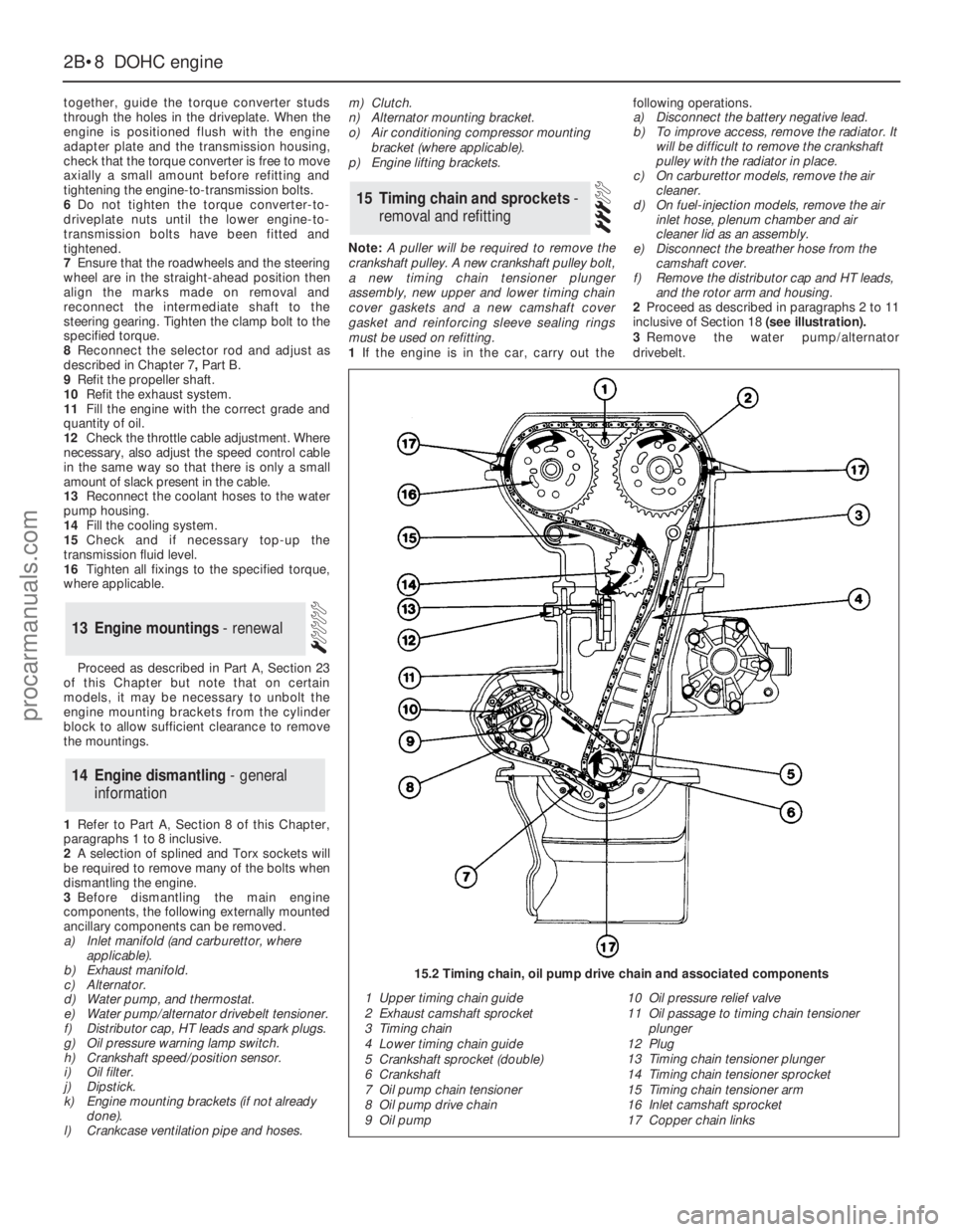
inclusive of Section 18 (see illustration).
3Remove the water pump/alternator
drivebelt.
15Timing chain and sprockets -
removal and refitting
14Engine dismantling - general
information
13Engine mountings - renewal
2B•8DOHCengine
1 Upper timing chain guide
2 Exhaust camshaft sprocket
3 Timing chain
4 Lower timing chain guide
5 Crankshaft sprocket (double)
6 Crankshaft
7 Oil pump chain tensioner
8 Oil pump drive chain
9 Oil pump10 Oil pressure relief valve
11 Oil passage to timing chain tensioner
plunger
12 Plug
13 Timing chain tensioner plunger
14 Timing chain tensioner sprocket
15 Timing chain tensioner arm
16 Inlet camshaft sprocket
17 Copper chain links
15.2 Timing chain, oil pump drive chain and associated components
procarmanuals.com
Page 86 of 255
See Chapter 1, Section 46.
See Chapter 1, Section 46.
See Chapter 1, Section 46.
1Drain the radiator. There is no need to drain
the cylinder block. On DOHC engines the
electric cooling fan assembly must be removed
to gain the clearance to remove the radiator.
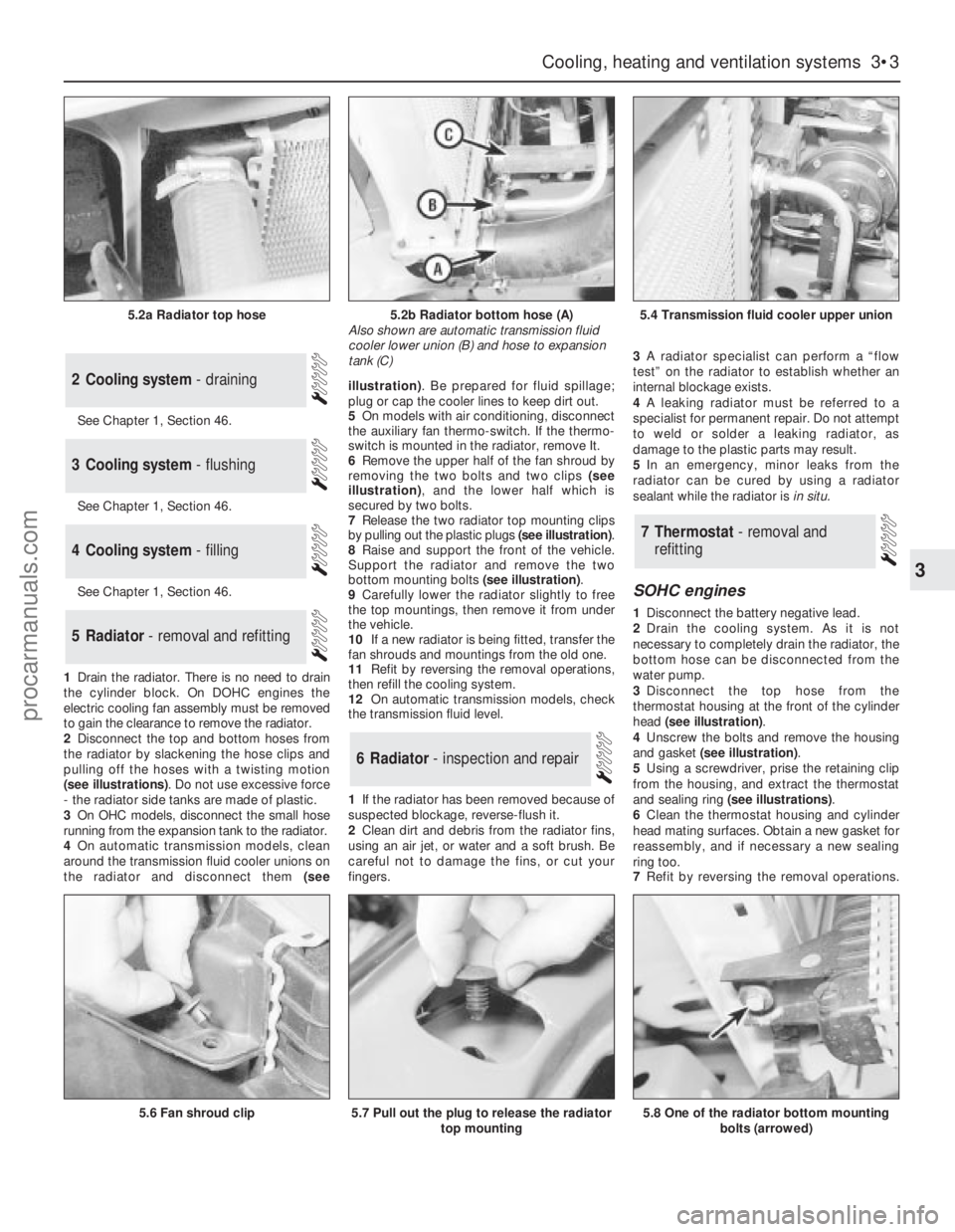
2Disconnect the top and bottom hoses from
the radiator by slackening the hose clips and
pulling off the hoses with a twisting motion
(see illustrations). Do not use excessive force
- the radiator side tanks are made of plastic.
3On OHCmodels, disconnect the small hose
running from the expansion tank to the radiator.
4On automatic transmission models, clean
around the transmission fluid cooler unions on
the radiator and disconnect them (seeillustration). Be prepared for fluid spillage;
plug or cap the cooler lines to keep dirt out.
5On models with air conditioning, disconnect
the auxiliary fan thermo-switch. If the thermo-
switch is mounted in the radiator, remove It.
6Remove the upper half of the fan shroud by
removing the two bolts and two clips (see
illustration), and the lower half which is
secured by two bolts.
7Release the two radiator top mounting clips
by pulling out the plastic plugs (see illustration).
8Raise and support the front of the vehicle.
Support the radiator and remove the two
bottom mounting bolts (see illustration).
9Carefully lower the radiator slightly to free
the top mountings, then remove it from under
the vehicle.
10If a new radiator is being fitted, transfer the
fan shrouds and mountings from the old one.
11Refit by reversing the removal operations,
then refill the cooling system.
12On automatic transmission models, check
the transmission fluid level.
1If the radiator has been removed because of
suspected blockage, reverse-flush it.
2Clean dirt and debris from the radiator fins,
using an air jet, or water and a soft brush. Be
careful not to damage the fins, or cut your
fingers. 3A radiator specialist can perform a “flow
test” on the radiator to establish whether an
internal blockage exists.
4A leaking radiator must be referred to a
specialist for permanent repair. Do not attempt
to weld or solder a leaking radiator, as
damage to the plastic parts may result.
5In an emergency, minor leaks from the
radiator can be cured by using a radiator
sealant while the radiator is in situ.
SOHC engines
1Disconnect the battery negative lead.
2Drain the cooling system. As it is not
necessary to completely drain the radiator, the
bottom hose can be disconnected from the
water pump.
3Disconnect the top hose from the
thermostat housing at the front of the cylinder
head (see illustration).
4Unscrew the bolts and remove the housing
and gasket (see illustration).
5Using a screwdriver, prise the retaining clip
from the housing, and extract the thermostat
and sealing ring (see illustrations).
6Clean the thermostat housing and cylinder
head mating surfaces. Obtain a new gasket for
reassembly, and if necessary a new sealing
ring too.
7Refit by reversing the removal operations.
7Thermostat - removal and
refitting
6Radiator - inspection and repair
5Radiator - removal and refitting
4Cooling system - filling
3Cooling system - flushing
2Cooling system - draining
Cooling, heating and ventilation systems 3•3
3
5.2a Radiator top hose5.2b Radiator bottom hose (A)
Also shown are automatic transmission fluid
cooler lower union (B) and hose to expansion
tank (C)5.4 Transmission fluid cooler upper union
5.6 Fan shroud clip5.7 Pull out the plug to release the radiator
top mounting5.8 One of the radiator bottom mounting
bolts (arrowed)
procarmanuals.com
Page 127 of 255
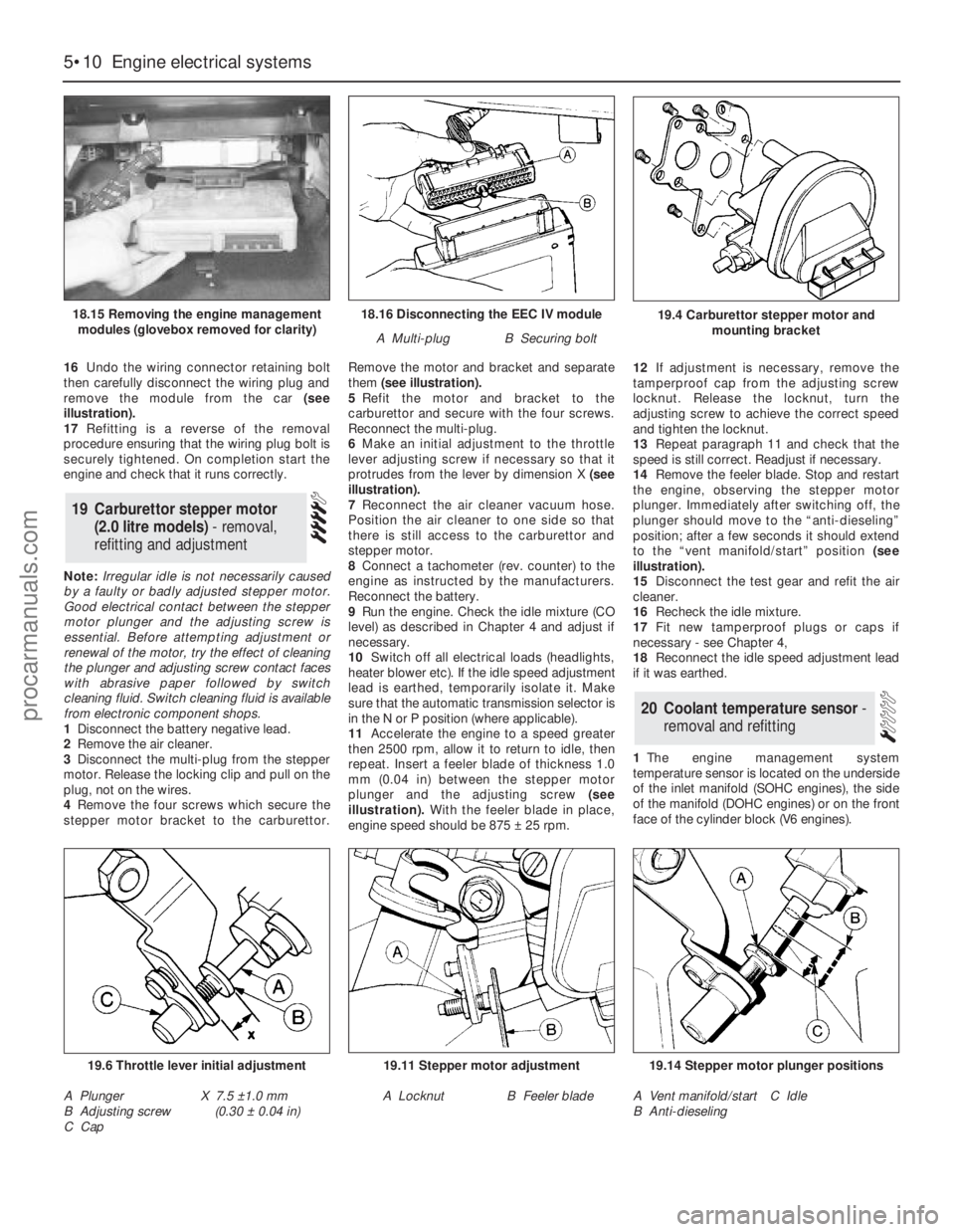
16Undo the wiring connector retaining bolt
then carefully disconnect the wiring plug and
remove the module from the car (see
illustration).
17Refitting is a reverse of the removal
procedure ensuring that the wiring plug bolt is
securely tightened. On completion start the
engine and check that it runs correctly.
Note: Irregular idle is not necessarily caused
by a faulty or badly adjusted stepper motor.
Good electrical contact between the stepper
motor plunger and the adjusting screw is
essential. Before attempting adjustment or
renewal of the motor, try the effect of cleaning
the plunger and adjusting screw contact faces
with abrasive paper followed by switch
cleaning fluid. Switch cleaning fluid is available
from electronic component shops.
1Disconnect the battery negative lead.
2Remove the air cleaner.
3Disconnect the multi-plug from the stepper
motor. Release the locking clip and pull on the
plug, not on the wires.
4Remove the four screws which secure the
stepper motor bracket to the carburettor.Remove the motor and bracket and separate
them (see illustration).
5Refit the motor and bracket to the
carburettor and secure with the four screws.
Reconnect the multi-plug.
6Make an initial adjustment to the throttle
lever adjusting screw if necessary so that it
protrudes from the lever by dimension X (see
illustration).
7Reconnect the air cleaner vacuum hose.
Position the air cleaner to one side so that
there is still access to the carburettor and
stepper motor.
8Connect a tachometer (rev. counter) to the
engine as instructed by the manufacturers.
Reconnect the battery.
9Run the engine. Check the idle mixture (CO
level) as described in Chapter 4 and adjust if
necessary.
10Switch off all electrical loads (headlights,
heater blower etc). If the idle speed adjustment
lead is earthed, temporarily isolate it. Make
sure that the automatic transmission selector is
in the N or P position (where applicable).
11Accelerate the engine to a speed greater
then 2500 rpm, allow it to return to idle, then
repeat. Insert a feeler blade of thickness 1.0
mm (0.04 in) between the stepper motor
plunger and the adjusting screw(see
illustration).With the feeler blade in place,
engine speed should be 875 ±25 rpm. 12If adjustment is necessary, remove the
tamperproof cap from the adjusting screw
locknut. Release the locknut, turn the
adjusting screw to achieve the correct speed
and tighten the locknut.
13Repeat paragraph 11 and check that the
speed is still correct. Readjust if necessary.
14Remove the feeler blade. Stop and restart
the engine, observing the stepper motor
plunger. Immediately after switching off, the
plunger should move to the “anti-dieseling”
position; after a few seconds it should extend
to the “vent manifold/start” position (see
illustration).
15Disconnect the test gear and refit the air
cleaner.
16Recheck the idle mixture.
17Fit new tamperproof plugs or caps if
necessary - see Chapter 4,
18Reconnect the idle speed adjustment lead
if it was earthed.
1The engine management system
temperature sensor is located on the underside
of the inlet manifold (SOHC engines), the side
of the manifold (DOHC engines) or on the front
face of the cylinder block (V6 engines).
20Coolant temperature sensor -
removal and refitting
19Carburettor stepper motor
(2.0 litre models) - removal,
refitting and adjustment
5•10Engine electrical systems
18.16 Disconnecting the EEC IV module
A Multi-plugB Securing bolt
19.6 Throttle lever initial adjustment
A Plunger
B Adjusting screw
C CapX 7.5 ±1.0 mm
(0.30 ±0.04 in)
19.11 Stepper motor adjustment
A LocknutB Feeler blade
19.14 Stepper motor plunger positions
A Vent manifold/start
B Anti-dieselingC Idle
19.4 Carburettor stepper motor and
mounting bracket18.15 Removing the engine management
modules (glovebox removed for clarity)
procarmanuals.com
Page 161 of 255
Where serious damage has occurred or
large areas need renewal due to neglect, it
means certainly that completely new sections
or panels will need welding in and this is best
left to professionals. If the damage is due to
impact, it will also be necessary to completely
check the alignment of the bodyshell
structure. Due to the principle of construction,
the strength and shape of the whole car can
be affected by damage to one part. In such
instances the services of a Ford agent with
specialist checking jigs are essential. If a body
is left misaligned, it is first of all dangerous as
the car will not handle properly, and secondly
uneven stresses will be imposed on the
steering, engine and transmission, causing
abnormal wear or complete failure. Tyre wear
may also be excessive.
1Open and prop the bonnet.
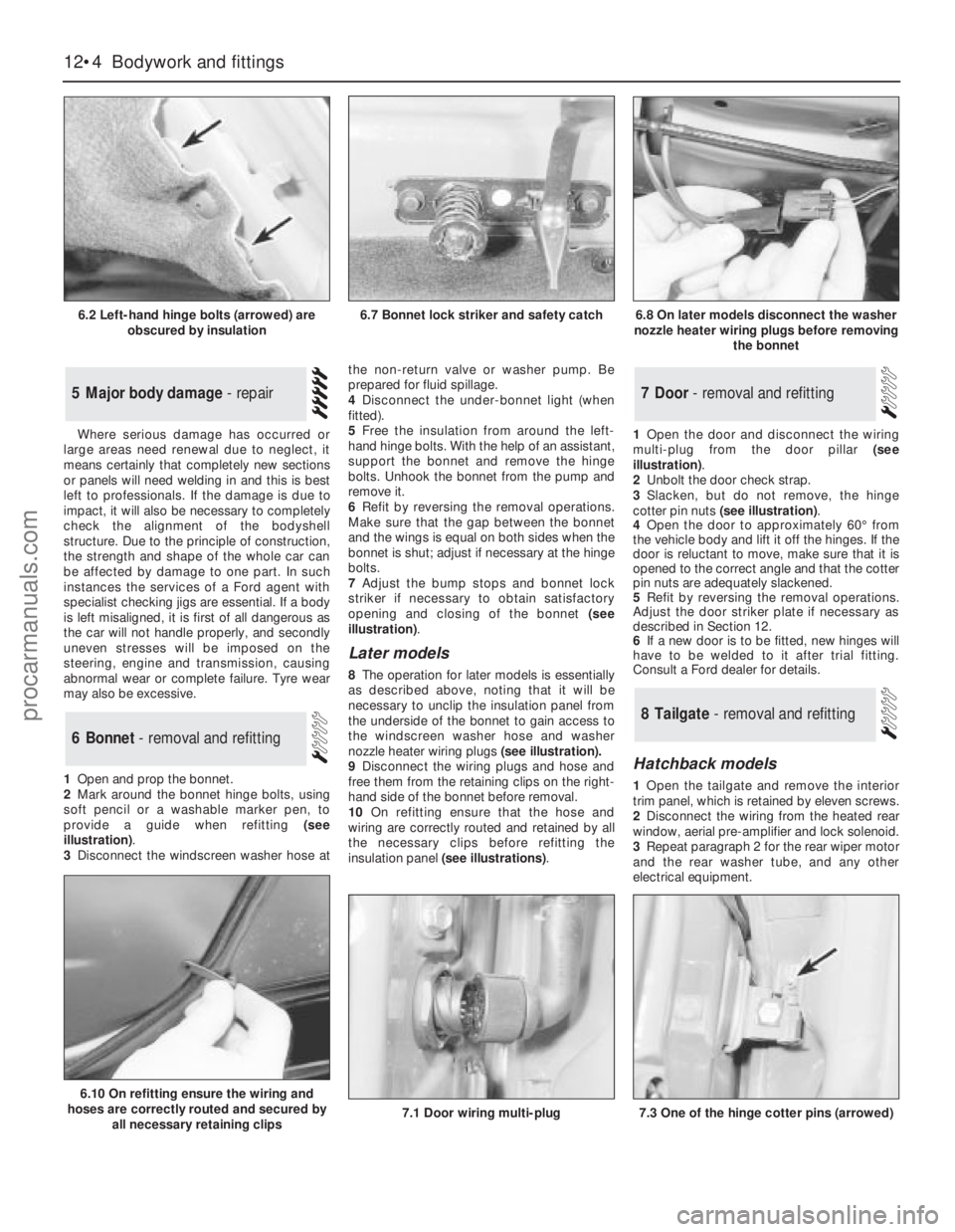
2Mark around the bonnet hinge bolts, using
soft pencil or a washable marker pen, to
provide a guide when refitting (see
illustration).
3Disconnect the windscreen washer hose atthe non-return valve or washer pump. Be
prepared for fluid spillage.
4Disconnect the under-bonnet light (when
fitted).
5Free the insulation from around the left-
hand hinge bolts. With the help of an assistant,
support the bonnet and remove the hinge
bolts. Unhook the bonnet from the pump and
remove it.
6Refit by reversing the removal operations.
Make sure that the gap between the bonnet
and the wings is equal on both sides when the
bonnet is shut; adjust if necessary at the hinge
bolts.
7Adjust the bump stops and bonnet lock
striker if necessary to obtain satisfactory
opening and closing of the bonnet (see
illustration).
Later models
8The operation for later models is essentially
as described above, noting thatit will be
necessary to unclip the insulation panel from
the underside of the bonnet to gain access to
the windscreen washer hose and washer
nozzle heater wiring plugs (see illustration).
9Disconnect the wiring plugs and hose and
free them from the retaining clips on the right-
hand side of the bonnet before removal.
10On refitting ensure that the hose and
wiring are correctly routed and retained by all
the necessary clips before refitting the
insulation panel (see illustrations).1Open the door and disconnect the wiring
multi-plug from the door pillar (see
illustration).
2Unbolt the door check strap.
3Slacken, but do not remove, the hinge
cotter pin nuts (see illustration).
4Open the door to approximately 60°from
the vehicle body and lift it off the hinges. If the
door is reluctant to move, make sure that it is
opened to the correct angle and that the cotter
pin nuts are adequately slackened.
5Refit by reversing the removal operations.
Adjust the door striker plate if necessary as
described in Section 12.
6If a new door is to be fitted, new hinges will
have to be welded to it after trial fitting.
Consult a Ford dealer for details.
Hatchback models
1Open the tailgate and remove the interior
trim panel, which is retained by eleven screws.
2Disconnect the wiring from the heated rear
window, aerial pre-amplifier and lock solenoid.
3Repeat paragraph 2 for the rear wiper motor
and the rear washer tube, and any other
electrical equipment.
8Tailgate - removal and refitting
7Door - removal and refitting
6Bonnet - removal and refitting
5Major body damage - repair
12•4Bodywork and fittings
6.2 Left-hand hinge bolts (arrowed) are
obscured by insulation
6.10 On refitting ensure the wiring and
hoses are correctly routed and secured by
all necessary retaining clips
7.1 Door wiring multi-plug7.3 One of the hinge cotter pins (arrowed)
6.7 Bonnet lock striker and safety catch6.8 On later models disconnect the washer
nozzle heater wiring plugs before removing
the bonnet
procarmanuals.com