Page 2 of 116

HOW TO READ DIAGRAMS
I
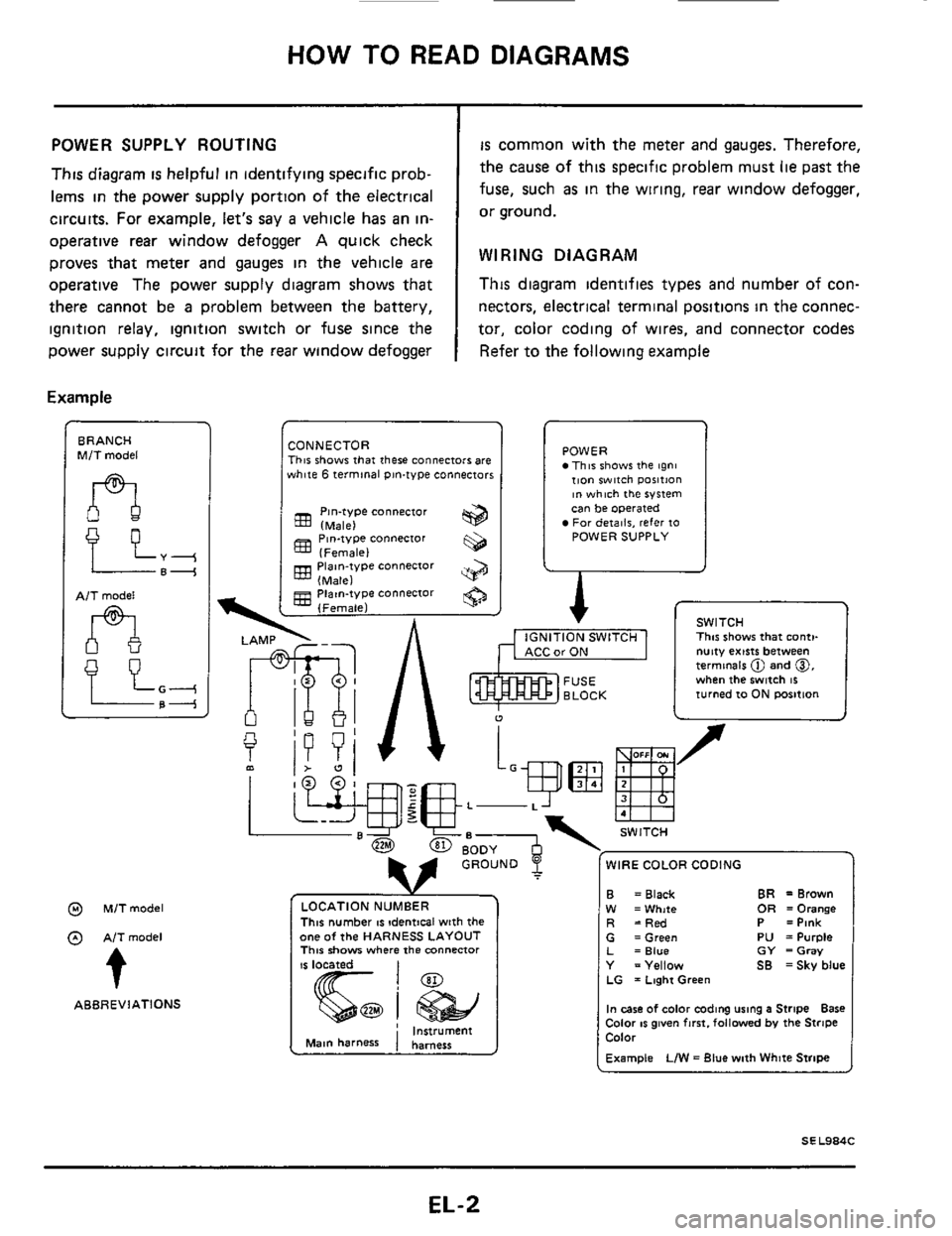
POWER SUPPLY ROUTING
This diagram is helpful in identifying specific prob-
lems
in the power supply portion of the electrical
circuits. For example, let's say
a vehicle has an in-
operative
rear window defogger A quick check
proves that meter and
gauges in the vehicle are
operative The power supply diagram shows that
there cannot be
a problem between the battery,
ignition relay, ignition switch or fuse since the
power supply circuit for the
rear window defogger
Example
BRANCH M/T model
AlT model
n
@ M/Tmodel
@ AITmodel
t
ABBREVIATIONS
is common with the meter and gauges. Therefore,
the cause of this specific problem must
lie past the
fuse, such
as in the wiring, rear window defogger,
or ground.
WIRING DIAGRAM
This diagram identifies types and number of con-
nectors, electrical
terminal positions in the connec-
tor, color coding of wires, and connector codes
Refer to the following example
CONNECTOR This shows that there connectors are white 6 terminal pin-type connectors
Pin-type connector (Male)
(Female)
(Male)
(Female)
833 Piaan-type connector
gg Piatn-type connector
POWER This shows the tgni tion witch ~osition ~n which the system can be operated For deiailr, refer 10 POWER SUPPLY
A r
I
1 v SWITCH ., , ,-,. -..,m I This shows that conti-
u
f
L-
WIRE COLOR CODING
This number IS !dentical with the one of the HARNESS LAYOUT This show where the mnnenor
CarON I nutty exists between termmels @ and 0, when the switch 16 turned 10 ON rmition
B W R
BR =Brown = Black OR =Orange =White =Red P =Pink G =Green PU =Purple L =Blue GY =Gray Y =Yellow SB =Sky blue LG = Laghi Green
In case of color coding using a Stripe Bare Color IS given fmt. followed by the Stripe Color
Example LIW = Blue with White Stripe
EL-2
Page 16 of 116

CHARGING SYSTEM
Make sure "S ' termmal 8s con- IC-RG IC regulator
When reaching "Damaged
A C G.", remove
0 K. IC-alternator 16 In good condltlon nected COrreCtly
Trouble-Shooting
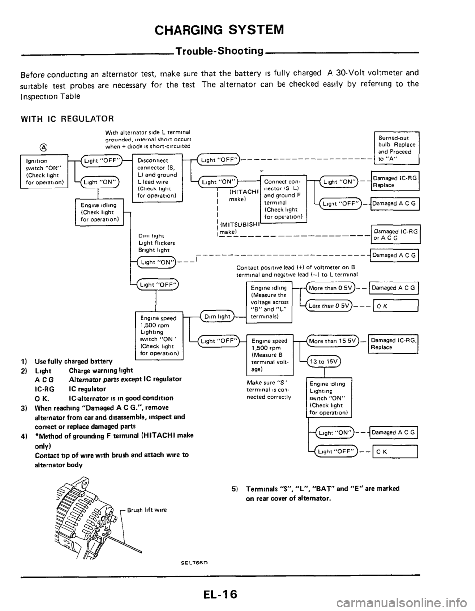
Before conducting an alternator test, make sure that the battery IS fully charged A 30-Volt voltmeter and
suitable test probes are necessary for the test The alternator can
be checked easily by referrmg to the
Inspection Table
Engine tdltng Lighting $witch "ON,, (Check light for operatlonl
WITH IC REGULATOR
bulb Replace and Proceed -
Wpth alternator side L terminal grounded, internal short occurs when + diode IS short-circuited @
Ignition witch "ON" cOnneCtor IS. (Check light Ll and ground for operatton1 L lead w~re Connect con-
I lH,TACHl nector IS LI far operation1 and ground F
I [Check Itght I for operation1
I (MITSUBISHI ' makel I - - - - - - - - - - - - -------- -
J
..........................
Contact poiitwe lead (+I of voltmeter on B
Lqht "OFF"
9
Engine speed 1,500 rpm
terminal and negative lead (-1 to L terminal
(Measure the "oltage acres "E" and "L"
only)
Contact tip of wlre with brush and attach wire to
alternator body -0 Light"0FF" -- OK
5) Terminals "S", "L", "BAT" and "E" are marked
on rear cover
of alternator.
Brush lift wire
SEL766D
EL-1 6
Page 19 of 116
CHARGING SYSTEM -Alternator-
Brush Check
1 Check smooth movement of brush
Not smooth Check brush holder and
clean
2 Check brush for wear
SEL631D
Replace brush if it is worn down to the
3. Check brush pig tail for damage
Damaged Replace
4 Check brush spring pressure
Measure brush spring pressure with brush pro-
jected approximately
2 mm (008 in) from
brush holder
Spring pressure.
limit line
1.471 - 3.531 N (150 - 360 9,
5.29 - 12.70 02) [HITACHI make]
10.93 - 15 17 02) [MITSUBISHI make]
3.040 - 4 217 N (310 - 430 9,
2 mm (0 08 in1
IP-
EE049
Not in the specified value Replace
- Stator Check
To test the stator or diode, you must separate
them
by unsoldering the connecting wires.
CAUTION.
Used only
as much heat as required to melt solder.
Diodes will
be damaged by excessive heat.
Long nose pliers used a$ a heal sink
-1, /
SEL054D
1 Continuity test
y_ Lead wire -
SEL070
No continuity Replace stator
2 Ground test
SE LO7 1
Continuity exists Replace stator
EL-19
Page 22 of 116
CHARGING SYSTEM -Alternator-
Service Data and Specification
LR170-701B
Applied model
A2T48195
Nominal rating V-A
Ground wlarity
Minimum revolution undt no-load (when 14 volts IS
applied) rpm
Hot output current
Alrpm
Regulated output voltage
V
Minimum length of brush rnm (m)
Brush spring pressure
N 1% 02)
Slip ring outer diameter
mm Ion)
W8thout turbo With turbocharger
charaer models models
12-70
Negative
Less than 1.000
More than
2111,300
More than
5012,500
More than
7015,000
144-150
More than
55102171
1,471 - 3,531
1150-360.
5 29
- 12 701
More than
21
6 IO 850)
Less than 1,100
More than
21 11,300
More than
5012,500
141 147
More than
8 10311
3,040 4,217
I310
- 430,
1093- 15 17)
More than
22 4
10 8821
Page 33 of 116

HEADLAMP
0
0
Headlamp Motor Check
0 No
8 Yes
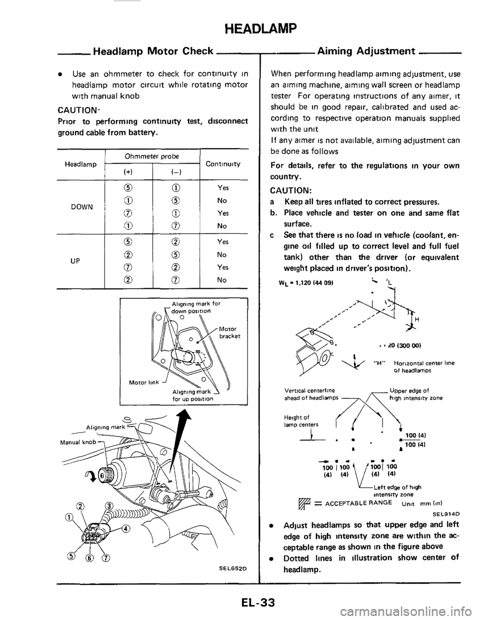
Use an ohmmeter to check for continuity in
headlamp motor circuit while rotating motor
with manual knob
CAUTION.
Prior to performing continuity test, disconnect
ground cable from battery.
Ohmmeter probe
Headlamp Continuity
Yes
No
Alqning mark for
for up posltlon
SEL652D
- Aiming Adjustment
When performing headlamp aiming adjustment, use
ail aiming machine, aiming wall screen or headlamp
tester For operating instructions of any airner, it
should be in good repair, calibrated and used ac-
cording to respective operation manuals supplied
with the unit
If any aimer is not available, aiming adjustment can
be done
as follows
For details, refer to the regulations in your own
country.
CAUTION:
a Keep all tires inflated to correct pressures.
b. Place vehicle and tester on
one and same flat
surface.
c See that there is no load in vehicle (coolant, en-
gine oil filled up to correct level and full fuel
tank) other than
the driver (or equivalent
weight placed in driver's position).
W~=l,ltO(4409I c 'L
-7
, - LO 1300 001
Of headlamps
UPper edge of Vertical centerline ahead of headlamps -x high tntenrw zone
Height of lamp centers I .- 100 141
100 (41 .-
L A
4.. I.. 100 1100 1001 loo (41 (41 / (41 (41
KLeft edge of high intensity zone
= ACCEPTABLE RANGE untt mm (in1
SEL914D
Adjust headlamps so that upper edge and left
edge
of high intensty zone are within the ac-
ceptable range as shown
in the figure above
Dotted lines in illustration show center of
headlamp.
EL-33
Page 34 of 116
FUSE
BLOCK
r
BATTERY
Ll-J
I I
BODY GROUND
SIDE MARKER IR H ridel LAMP R H BODYGROUND
FRONT COMBINATION L/Y-
LAMP R H L/OR -
@ STOP LAMP SWITCH
CLEARANCE
BODY GROUND
CLEARANCE
BODY GROUND
(L H ridel
CLEARANCE
(Engine room harness1
IWhm
-R/G-
FRONT COMBINATION
LAMP L H
b VI w 0
SIDE MARKER
LAMP L H
TAIL AN0 STOP
LAMPSENSOR
0 SFmodelr
@ GLrnodelr
@ GLLrnodelr
@ Digital type meter
@ Needle type meter
L H ride1
mm
BODYGROUND
(L H ridel
LICENSE
LAMP
REAR COMBINATION
LAMP L H
STOP
TAIL
R /G
REAR SIDE
MARKER LAMP L H
Page 35 of 116
EXTERIOR LAMP
Auxiliary Driving Lamp/Wiring Diagram
Back-up Lamp/Wiring Diagram
BODYGROUND (R H $idel
1 FUSEBLOCK -
REAR COMBINATION
LAMP R H IMsin hsmenl
IWh8te R H ridel
lEng8nc rubharnenl @ Non WrMcharger models @ BODY GROUND qCL H sidel - INHIBITOR WITCH SEL655D
EL-35
Page 36 of 116
rn r
i, m
BODY
GROUND
@
FRONT COMBINATION
LAMP R H
B- EMF G/R-
RH @
FRONT COMBINATION LAMP L H
1
s
LH @
@
BODY
GROUND
@ Digital tvPe carnb6nation meter
equnpped model
@ Needle type m combmation meter equlpped model rn r 0 In 01 0
BODYGROUND -
I I II
I 1 II I J
E%
TURN L H -0 I
REAR COMBINATION
@@ LAMP L H
IGNITION
SWITCH ON or START