Page 59 of 116
METER AND GAUGES -Digital Type Combination Gauge
Trouble-shooting
(+)
v
Check power supply circuit for combination
gauge
(-1
l°K 1 NG
Replace combination gauge Check harness
Voltmeter terminal I Ignition switch position
Approx Approx
@ I 03 I OV I 12v ! 12v
Continuity exists @ I gK:d I
Remove radio and A/C control assembly from
center console and remove combination gauge
with harness connected
Check from harness rtde
SEL681D
Display illumination will not darken when light
1 switch is "ON"
I Check light switch circuit for combination gauge I
1 Remove radio and A/C control assembly
and remove combination gauge with har-
ness connected.
Turn ignition switch to
"OFF"
Turn light switch to "ON"
Measure voltage across @ and @
2
3
4
Ignition switch - 0
ht switch - ON
SEL682D L
EL-59
Page 78 of 116
VOICE WARNING SYSTEM
Operational Check
Fuel level
I Condition I Voice Warning -~ ~
Item
Fuel level less than
1OP (2-5/8USgal, - “Fuel level is low’’
2-1/4 Imp gal) ~~
Left
door
Door switch L H is “ON“
(Left door is open)
ignition switch
“OFF” Light
Door switch L H is
”ON”
(Left door is open)
Lighting switch is “ON” “Lights are ON”
“Left door is open”
Speed switch is “ON”
Vehicle speed is more
than
10 km/h (6 MPH)
Door switch R H is
”Right door is open”
Parking brake switch Parking brake is “ON” ”Parking brake is ON”
e If rhe warning is not properly given under the above condition, go to “Trouble-Shooting”.
EL-78
Page 79 of 116
VOICE WARNING SYSTEM
Trou ble-shooting
Voltmeter
Condition
1 Ignition sw "ACC"
Check if speaker in driver's door
produces sound wheri radio
is
turned "ON"
Ignition sw "OFF"
Normal
i
Check harness connector run-
ning to driver's door speaker
Lighting switch "ON"
Check voice warning switch
CNG>
More than 9V
Replace voice warning switch i
v
Disconnect connector running to voice warning device and check voltage
at each terminal of connector
I- I I
I OK T
Replace voice warning device
I NG i
Check harness
EL-79
Page 80 of 116
rn I-
0
do
Left door Right door Parking brake Fuel level Light
OK (7) Check if step lamp
left or right door
is opened
Check door switch
I
I
lxeed % Sensor
Signal Check"
-1 (Refer to "METER I
Check if fuel
warning lamp
comes on when Check if parking
brake warning
lamp comes on
when parking
brake lever
is
pulled with
ignition switch
"ON"
NG
Check parking
brake switch Check fuel tank
gauge unit
(Refer to "METER
AND GAUGES")
Repair or
replace
AND GAUGES" )
v
Check for loose connector,
poor grounding
or broken wire
'""I
Repair or
replace
OK
Replace voice warning device
Check if all illumi-
nation lamps come
on when lighting
switch
is "ON"
Check lighting
switch
Page 81 of 116
TIME CONTROL SYSTEM
CAUTION
Never touch the terminals of time control unit with bare hands.
1) Intermittent wiper control timer 5) Light warning timer
2) Interior lamp timer 6) Key warning timer
3) Door key hole illumination timer 7) Seat belt warning timer
4) Illumination control timer 8) Rear defogger timer
Time control unit has the following functions
ltNlTlON SWlTCH IGNITION lGNlTlON
FUSE
TlME CONTROLUNil /I
1
SEL705D
EL-81
Page 86 of 116

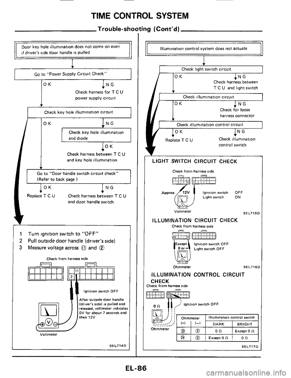
TIME CONTROL SYSTEM
Trouble-shooting (Cont'd)
BO
,@ @
Ohmmeter
Door key hole illumination does not come on even
if driver's side door handle
is pulled
I
illumination control switch
DARK BRIGHT
Except 0 R OR
Excepton OR
I Go to "Power Supply Circuit Check" I
Check harness for T C U
power supply circuit
, rK
Check key hole illumination circuit
I /OK I Check key hole illumination
Check harness between T C U
and key hole illumination
Go to "Door handle switch circuit check"
(Refer
to back oaqe 1
lNG Check harness between T C U
and door handle switch
l°K Replace T C U
1
2
3
Turn ignition switch to "OFF"
Pull outside door handle (driver's side)
Measure voltage across
0 and @
Check from harness side
Ignition witch OFF
After outside door handle Idrlver'r ride) 16 pulled and releared, voltmeter indicates OV for about 7 seconds and then 12V
Voltmeter
SEL714D
Illumination control system does not actuate
Check light switch circuit
T C U and light switch
Check illumination circuit
harness connector
Check illumination control circuit
control switch
LIGHT SWITCH CIRCUIT CHECK
Check from harness side
Ignition witch OFF Approx(i51j Light witch ON
u
SE L715C Voltmeter
ILLUMINATION CIRCUIT CHECK
Check from harness side
EL-86
Page 91 of 116
WIPER AND WASHER
Headlamp Washer/Wiring Diagram
HEADLAMP
RELAY
WASHER HEADLAMP @
: (Back ride)
HEADLAMP
WASHER
SWITCH
7
- 22 I1 BODY GROUND IR H ride)
HEADLAMP
WASHER
BODYGROUND (L H $#de)
@ GLmodelr
@ GLLrnodelr
@ Digital type meter
@ Needle type meiei
BODY GROl (R H ride)
II fWhw
(Engine room harnerr)
I LIGHTING SWITCH
J
(Main harness)
USE
7/1
w
II
IGNITION SWITCH I ACC or ON
I I
SEL727D
EL-91
Page 92 of 116
HORN, CIGARETTE LIGHTER, CLOCK
Wiring Diagram
SEL729D
EL-92