Page 27 of 116
-
BATTERY TI RFI AV 1 7
THEFT WARNING
r --, I II
I
"$ 7; '/' '
PASSING RELAY
k=a-J \-UPHOLD RELAY
I
1V.
@ Wnihoul headlamp warning
0 Wnh headlamp warning
Page 33 of 116

HEADLAMP
0
0
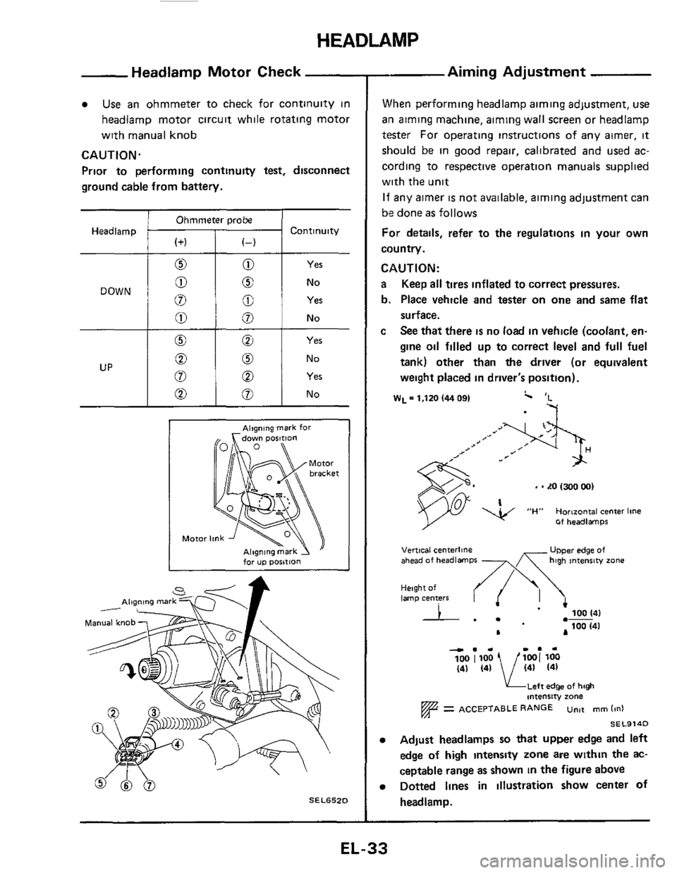
Headlamp Motor Check
0 No
8 Yes
Use an ohmmeter to check for continuity in
headlamp motor circuit while rotating motor
with manual knob
CAUTION.
Prior to performing continuity test, disconnect
ground cable from battery.
Ohmmeter probe
Headlamp Continuity
Yes
No
Alqning mark for
for up posltlon
SEL652D
- Aiming Adjustment
When performing headlamp aiming adjustment, use
ail aiming machine, aiming wall screen or headlamp
tester For operating instructions of any airner, it
should be in good repair, calibrated and used ac-
cording to respective operation manuals supplied
with the unit
If any aimer is not available, aiming adjustment can
be done
as follows
For details, refer to the regulations in your own
country.
CAUTION:
a Keep all tires inflated to correct pressures.
b. Place vehicle and tester on
one and same flat
surface.
c See that there is no load in vehicle (coolant, en-
gine oil filled up to correct level and full fuel
tank) other than
the driver (or equivalent
weight placed in driver's position).
W~=l,ltO(4409I c 'L
-7
, - LO 1300 001
Of headlamps
UPper edge of Vertical centerline ahead of headlamps -x high tntenrw zone
Height of lamp centers I .- 100 141
100 (41 .-
L A
4.. I.. 100 1100 1001 loo (41 (41 / (41 (41
KLeft edge of high intensity zone
= ACCEPTABLE RANGE untt mm (in1
SEL914D
Adjust headlamps so that upper edge and left
edge
of high intensty zone are within the ac-
ceptable range as shown
in the figure above
Dotted lines in illustration show center of
headlamp.
EL-33
Page 34 of 116
FUSE
BLOCK
r
BATTERY
Ll-J
I I
BODY GROUND
SIDE MARKER IR H ridel LAMP R H BODYGROUND
FRONT COMBINATION L/Y-
LAMP R H L/OR -
@ STOP LAMP SWITCH
CLEARANCE
BODY GROUND
CLEARANCE
BODY GROUND
(L H ridel
CLEARANCE
(Engine room harness1
IWhm
-R/G-
FRONT COMBINATION
LAMP L H
b VI w 0
SIDE MARKER
LAMP L H
TAIL AN0 STOP
LAMPSENSOR
0 SFmodelr
@ GLrnodelr
@ GLLrnodelr
@ Digital type meter
@ Needle type meter
L H ride1
mm
BODYGROUND
(L H ridel
LICENSE
LAMP
REAR COMBINATION
LAMP L H
STOP
TAIL
R /G
REAR SIDE
MARKER LAMP L H
Page 39 of 116
FUSE BLOCK
I BATTERY I
TIME CONTROL UNIT [Refer to "TIME
CONTROL
SYSTEM
I I
LIR
@ SF models
IWhiIel DOOR STEP @ GLmodelr (Door harness R H I LAMP R H @ GLLmodelr
@ D8g1tal tv~e meter
@) Needle type meter
J~/~U
LIR U
I 1 II I
. BODY GROUND IL H ridel
Page 53 of 116

METER AND GAUGES - Digital Type Combination Meter
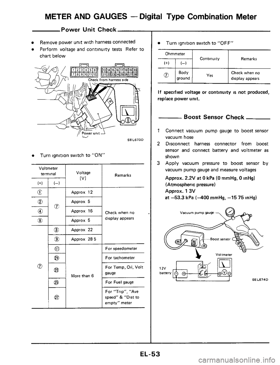
Power Unit Check
Voltmeter
terminal
(f) (-)
E -
-%; 0
0
@I
__
@
9
0
0
Remove power unit with harness connected
Perform voltage and continuity tests Refer to
chart below
I Voltage
[VI
Approx 12
Approx 5
Approx 16
Approx 5
Approx 22
Approx 285
Turn ignition switch to "ON"
1 - 1 More than 6
Remarks
Check when no
display appears
For speedometer
For tachometer
For Temp,
Oil, Volt
sause
For Fuel gauge
For "Trip", "Ave
speed"
& "Dirt to
empty" meter
Turn ignition switch to "OFF"
Ohmmeter
Continuity Remarks
Check when no
ground display appears
If specified voltage or continuity is not produced,
replace power unit.
- Boost Sensor Check
1 Connect vacuum pump gauge to boost sensor
vacuum hose
2 Disconnect harness connector from boost
sensor and connect battery and voltmeter
as
shown
3 Apply vacuum pressure to boost sensor by
vacuum pump gauge and measure voltages
Approx.
2.2V at 0 kPa (0 mmHg, 0 inHg)
(Atmospheric pressure)
Approx.
1 3V
at -53.3 kPa (-400 mmHg, -15 75 inHg)
vacuum pump gauge
SEL674D
EL-53
Page 96 of 116
AUDIO AND POWER ANTENNA
Power Antenna Motor Check
1 Disconnect, at connector, harness between
power antenna unit and antenna timer.
2 Apply 12-volt battery voltage across @ and
@ to make Sure antenna rod extends and
retracts
3. Connect a voltmeter across terminal 0 and
ground terminal
of battery.
4 Check to determine if voltmeter varies between
0 and 12 volts (approx ) in relation to move-
ment
of antenna rod when 12-volt battery
voltage
IS applied across @ and @
If above test results are not satisfactory, re-
place antenna
motor.
SEL732D
Radio Fuse Check
SEL733D
EL-96
Page 102 of 116

AUTOMATIC SPEED CONTROL DEVICE (A.S.C.D.)
- Trouble-shooting (Cont'd)
AIT model only
0 When A S C D is set while vehicle is operating
in
"0 D " range, 0 D will be cancelled and
shifting to
0 D cannot be made thereafter
0 While vehicle is being driven using AS C D in
"0 D "range, 0 D will not be cancelled even
if actual car speed is 6 kmlh (4 MPH) lower
than
set speed (Set speed cannot be main-
tained
)
1 Check 0 D cancel circuit for AS C D control unit I
Replace A S C D 0 Electroniccontrolled A/T
control unit Check harness between
lock-up control unit and
AS C D control unit
Check harness between
0 D. cancel solenoid.
i) D. cancel switch and
AS C D control unit
0 Conventional Ail
I
ELECTRONIC-CONTROLLED A/T
EQUIPPED MODEL (E4N71B)
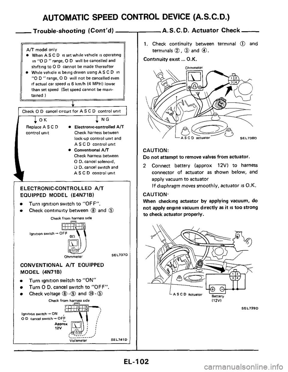
Turn ignition switch to "OFF".
Check continuity between @ and @
Check from harness slde . .~
ignmon switch - OFF
SEL737D Ohmmeter
CONVENTIONAL A/T EQUIPPED
MODEL (4N71B)
Turn ignition switch to "ON"
Turn 0 D. cancel switch to "OFF".
Check voltage @ -0 and 0-0
Check from harness side A '- b9ndt'~~n~~~~i~hO_N 0 Fihz L
Approx 12v ,I { .__. _- I .__.__.__.- -' Volmeter SEL741D
A.S.C.D. Actuator Check
1. Check continuity between terminal @ and
Continuity exist
... O.K.
terminals 0, @ and 0.
CAUTION:
Do
not attempt to remove valves from actuator.
2 Connect battery (approx 12V) to harness
connector
of actuator as shown below, and
apply vacuum to actuator
If diaphragm moves smoothly, actuator IS O.K.
CAUTION.
When checking actuator by applying vacuum, do
not apply engine vacuum directly
as it IS too strong
to check actuator properly.
LA s c D actuator B,m, 112VI
SEL739D
EL-I 02