Page 65 of 77
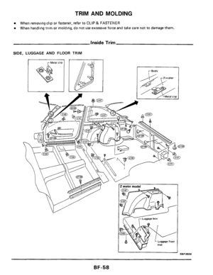
WINDSHIELD AND WINDOWS
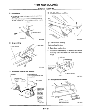
Back Door Window
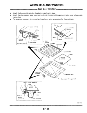
Attach the lower moldmg to the glass before installmg the glass.
Attach the glass stopper (glass upper portion) and the slde molding grommet to the panel before install-
ing the
glass
The remaining procedure for removal and lnstallatlon IS the same as that for the windshield.
//[ Upper molding
Glarr - ,
Lower molding
I 1 5 mrn 10.059 In1
Back door Panel
'L GI~~S stopper IAt hing center)
SSF419B
BF-65
Page 66 of 77
WINDSHIELD AND WINDOWS
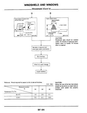
Side Window
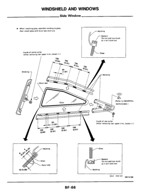
When innalling glass. assemble molding to glass.
fhen insla11 glass with butyl seal and nuts
lnrlde of center pillar (After removing rear upper frlm. loosen I1 1
i 7nn
Do not add too much as 11 will ooze out
[Refer to GENERAL
SERVICING
1
Inride of rear pol
Glarr
Sealant Do not add loo much as 11 wtll ooze out
Molding
SBF418B Umt mm Id
BF-66
Page 67 of 77
WINDSHIELD AND WINDOWS
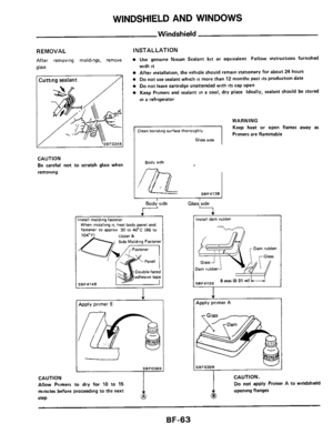
Repairing Leaks
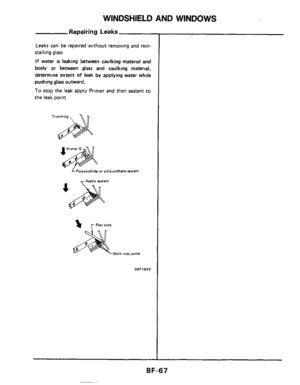
Leaks can be repaired without removing and rein-
stalling
glass
If water is leaking between caulking material and
body or between glass and caulking material,
determine extent
of leak by applying water while
pushing glass outward.
To stop the leak apply Primer and then sealant to
the leak Doint
L Polvwlphide or polyurethane sealant
% r Fiat stick
Work into joints
SBFl82B
BF-67
Page 68 of 77
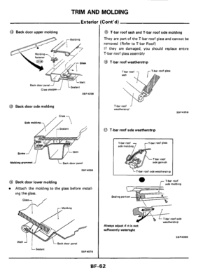
T-BAR ROOF
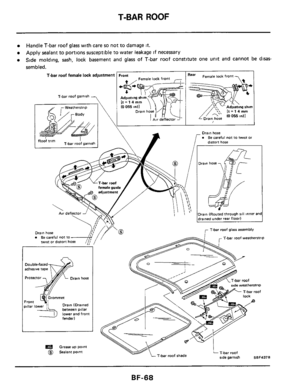
Handle T-bar roof glass wlth care so not to damage It.
Apply sealant to portlons susceptible to water leakage If necessary
Side molding, sash, lock basement and
glass of T-bar roof constitute one unit and cannot be disas-
sembled.
T-bar roof female lock adJUStmen1 Front Rea' Female lock fron
Air deflector A
T-bar roof garnish -
I I
T-bar roof glass assembly '/Y'o / Drain hose Be careful not to twist or distort ho- T-bar roof weatherstrip
_t-
SBF437B T-bar roof shade
Drain (Drained beween pillar lower and front
Grease UP point
@ Sealant point
BF-68
Page 69 of 77
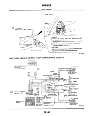
MIRROR
Door Mirror
1 Initial setting
23 3 (0 23. ONm ,O 31 kgm. 1 7.2 2 ft-lb)
of temporarily-lnrralled link (D Hook the bar With the hook and make sure It ts hooked
@ Tilt mirror body backward and while holding mirror. remove temporarily-Installed link
Never remove temporarily-installed link from mirror
body, before hooking the bar
with the hook
SBF4348 L
ELECTRICAL REMOTE CONTROL DOOR MlRRORNVlRlNG DIAGRAM
IWhntd
ImI mI nnAm
“1L-a
DOOR MIRROR
DEFOGGER
BF-69
Page 70 of 77
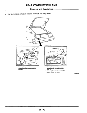
REAR COMBINAUION LAMP
Removal and installation
0 Rear combmation lamps are Installed with nuts and butyl sealant.
Warm up lamp assembly area to a temperatwe of a htth below 60'C (140'FI
Warm up lamp asembly ana to a temperature of a little below 60-C (140°F) Apply butyl seal evenly as It tends to become thin m the corners
SBF472B
BF-70
Page 71 of 77

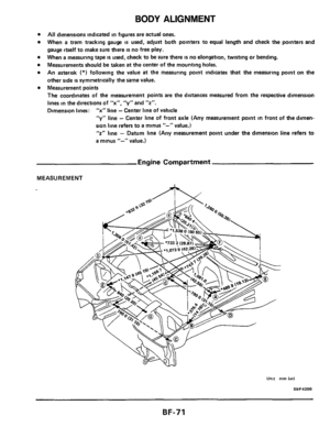
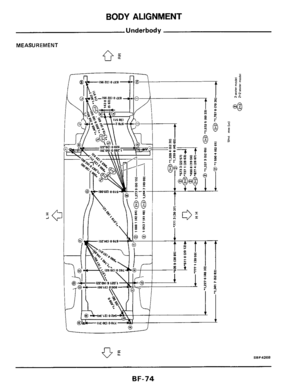
BODY ALIGNMENT
All dimensions indicated in figures are actual ones.
When
a tram tracking gauge is used, adjust both pointers to equal length and check the pointers and
gauge itself to make sure there
is no free play.
When
a measuring tape IS used, check to be sure there IS no elongation, twisting or bending.
Measurements should be taken
at the center of the mounting holes.
An asterisk
(*) following the value at the measuring point indicates that the measuring point on the
other side
is symmetrically the same value.
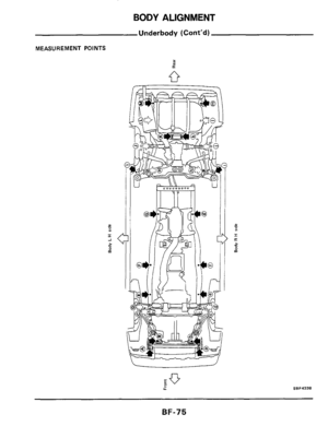
Measurement points
The coordinates of
the measurement points are the distances measured from the respective dimension
lines in the directions of
"x", "y" and "2".
Dimension lines: "x" line - Center line of vehicle
"y" line - Center line of front axle (Any measurement point in front of the dimen-
sion line refers to
a minus "-" value.)
"2" line - Datum line (Any measurement point under the dimension line refers to
a minus "-" value.)
Engine Compartment
MEASUREMENT
____
BF-71
Page 72 of 77
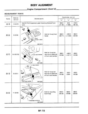
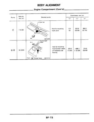
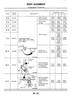
BODY ALIGNMENT
Engine Compartment (Cont’d)
MEASUREMENT POINTS
Points Hole dia
mm (in) Detailed points Coordinates mm (in)
“X” I, I, 2
540 5
(21 28) -
653 0
(2571)
26 a
(1 0551 -
-325 0
1-12 ao)
Hole for front suspension upper mounting (Outside front
hole) 919 0
(36 1 a)
852 0
(33 54)
490 0
(1 9 29)
490 0
(19 29)
966 0
(38 03)
12 (047)
9 (0 35)
5 4 (0 213)
a (0 31 )
IH
bumper rubber
SBF421B
Hole for fixing front
fender
Hole for fixing har-
ness clip
at upperside
of front side member 395 0
(15 55)
460 0
:-1811l
strut tower
Hole for fixing har-
ness clip
at upperside
of front side member 395 0
(15 55)
100 0
(3 941
Front ride member 1 SBFd23B
Hole for mounting
hood hinge 640 0
(25 20)
500 0
(19 69) 11 (043)
SB F 4248
BF-72
 and the slde molding grommet to the")


of temporarily-lnrralled link (D Hook the bar With the hook and make sure It ts hooked
@ Tilt mirror body backw")


MEASUREMENT POINTS
Points Hole dia
mm (in) Detailed points Coordinates mm (in)
“X” I, I, 2
540 5
(21 28) -
653 0
(2571)
26 a
(1 0551 -
-3")