Page 62 of 99
ASSEMBLY
46 Pour approx. 2-liters (2-1/8 US qt, 1-3/4 Imp
qt) of A T.F into converter housing
SAT518
47 Install torque converter to converter housing.
Be careful not to scratch front cover oil seal.
AT-62
Page 93 of 99

TROUBLE-SHOOTING AND DIAGNOSES
Stall
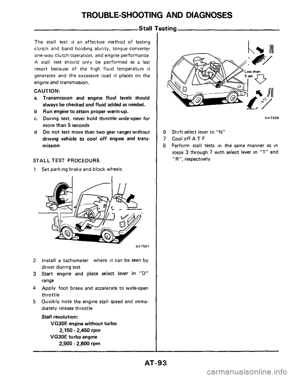
The stall test is an effective method of testing
clutch and band holding ability, torque converter
one-way clutch operation, and engine performance
A
stall test should only be performed as a last
resort because of the high fluid temperature it
generates and the excessive load it places on the
engine and transmission.
CAUTION:
a. Transmission and engine fluid levels should
b
c.
d
always be checked and fluid added as needed.
Run engine to
attain proper warm-up.
During test, never
hold throttle wide-open for
more than
5 seconds
Do not test more than two gear ranges without
driving vehicle to
cool off engine and trans-
mission
STALL TEST PROCEDURE
1 Set parking brake and block wheels
SAT597
2 Install a tachometer where it can be seen by
driver during
test
3 Start engine and place select lever in "D"
range
4 Apply foot brake and accelerate to wide-open
throttle
5 Quickly note the engine stall speed and imme-
diately release throttle
Stall revolution:
VG30E engine without turbo
VG30E turbo engine
2,150 - 2,450 rpm
2,500 - 2,800 rpm
SAT598
6
7 CooloffAT F
8 Perform stall tests in the same manner as in
steps 3 through 7 with select lever in "1" and
"R", respectively
Shift select lever to "N"
AT-93
Page 95 of 99

SERVICE DATA AND SPECIFICATIONS (S.D.S.)
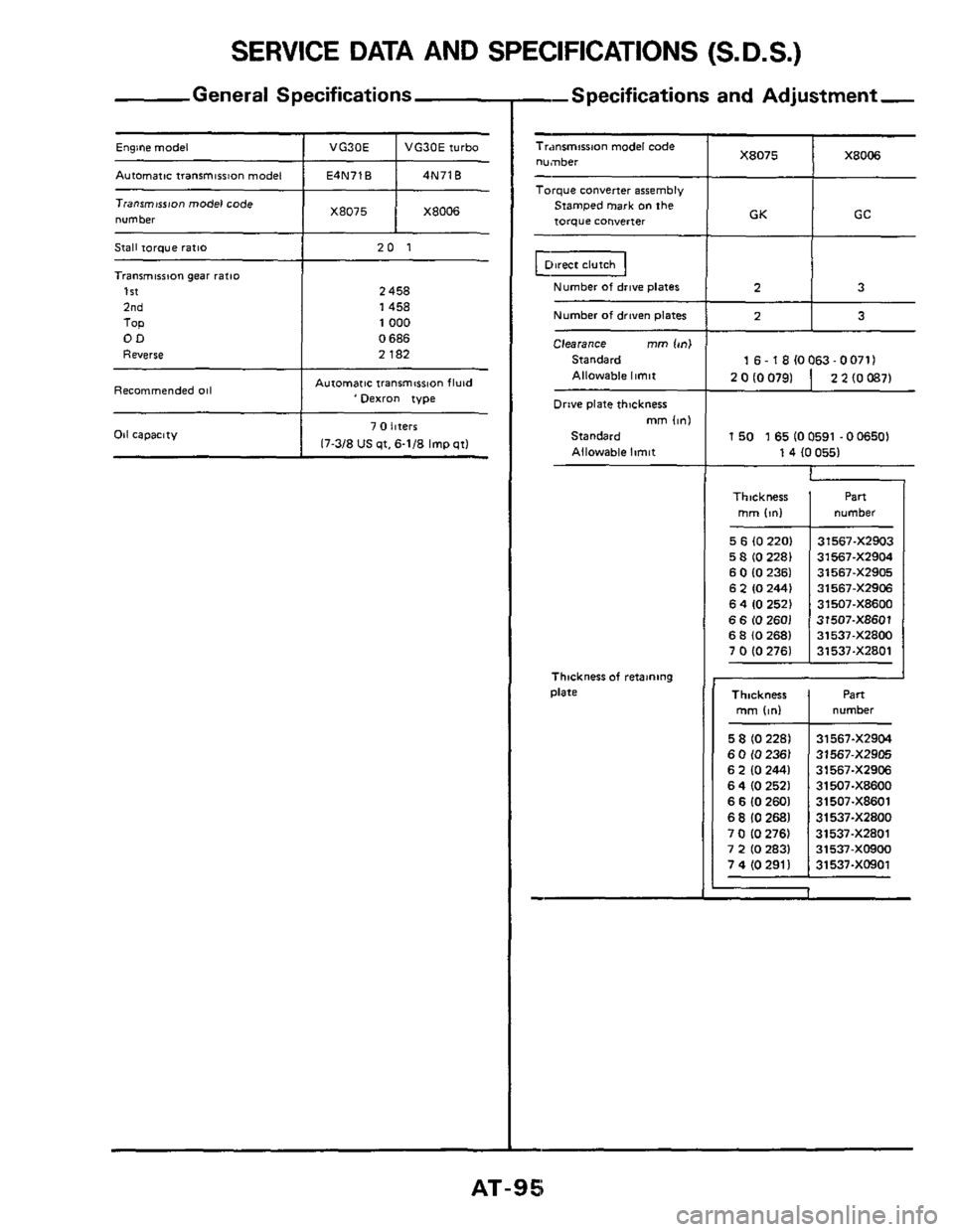
General Specifications
X8075 Engine model ~ I VG30E t VG30Eiurbo X8006 -
Autamatictranrmirrion model I E4N71B I 4N71B ~~
Stall torque ratlo
Transmission gear ratio
1st
2nd
TOP OD
Reverse
Recommended 011
1 X8075 1 X8006 Tianrmwon model code
number ~
20 1
2 458
1458
1000
0 686
2 182
Aurornar~c lranmwon fluid 'oexro" type
2 0 IO 0791
Oil capacity
2 2 (0 0871
7 0 hferr
17-3/8 US qt, 6-1/8 Imp qtl
5 6 (0 220)
5 8 (0 2281
6 0 (0 2361 6 2 IO 2441
6 4 10 2521
6 6 10 2601 6 8 (0 2681
7 0 (0 2761
--Specifications and Adjustment,
31567-XZ903
31567-XZ904
31567-XZ905
31567-XZ906
31507-X86W
31507-X8601
31537-XZ800
31537-XZ801
Tr.msmirrmn model code number
Torque converter assembly
Srarnped mark on the
torque COnYerter
Number of drive plates
Number of driven plates
Clearance rnm Ion1
Standard Allowable limit
Drive plate thickness mm (in1
Standard
Allowable limit
Thlcknesr of retamng
Dlate
1 GC GK
1 50 1 65 (0 0591 .O 06501
1 4 (0 0551
Thickness I numbel Part
mrn Iml
Thickness number
AT-95
Page 98 of 99

SERVICE DATA AND SPECIFICATIONS (S.D.S.)
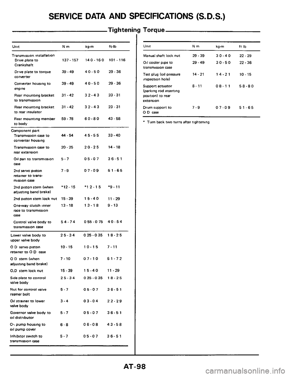
Tig hteni
Untt Nm kg-m ft-lb
Transmission mrtallation Drive plate to 137-157 140-160 101.116
Crankshaft
Drive plate to torque 39.49 4 0.5 0 29.36
converter
Converter housing to
39 - 49 4 0 - 5 0 29 - 36
engme
Rearmountingbracket
31 -42 32-43 23-31
to transmissnon
Rear mounting bracket
31 -42 3 2 - 4 3 23 - 31
to rear insulator
Rear mounting
member 59 - 78 6 0.8 0 43.58
to body
Camponent part
Transmission case to
converter housing
Transmission
case IO
rear extension
Od pan to transmissJon
case
2nd servo piston
retainer to trans- mission case
2nd piston stem (when adjusting band brake)
2nd mston stem lock nut
Onway clutch inner
race to transmission
Control valve body to
transmission case
Wle
44.54
20.25
5-7
7-9
'12-15
15-39
13-18
54-74
45-55 33-40
20-25 14-18
05-07 36-51
07-09 51-65
'12-15 *9.11
15-40 11-29
13-18 9-13
055-075 40-54
Lower valve body to 25-34 025-035 18-25
upper valve body
0 D servo pinon 10- 15 10-15 7-11
retainer to 0 D case
0 D stem (when 7-10 07-10 51-72
adjusting band brake)
0.D stem lock nut 15-39 15-40 11-29
Side Plate to Control 25-34 025-035 18-25 valve body
Nut for control valve 5-7 05-07 36-51
reamer bolt
011 strainer to lower 3-4 03-04 22-29
valve body
Governor MIM body to 5 - 7 05-07 36-51
011 distrtbutor
O*, pump housing to 6-8 06-08 43-58 011 pump cover
Inhibitor switch
to 5-7 05-07 36-51
transmission case
I Torque
U"lt Nm kgm ft Ib
Manual shaft lock nut 29.39 30-40 22-29
011 cooler pipe to 29 - 49 30-50 22-36 transmission case
Test plug
lo11 pressure 14-21 14-21 10-15 inspection hole)
Support actuator 8- 11 08-11 58-80
(parking rod inserting
position) to
rear
extension
Drum support to 7-9 07-09 51-65 0 D case
* Turn back two turns after tightening
Page 99 of 99
SPECIAL SERVICE TOOLS
Tool number
(Kent-Moore
No )
Tool name
ST07870000
(-) (ST07860000)
(J25605)
Transmission
case stand
ST25850000
(525721)
Sliding hammer
GG91060000
(-) (GG93010000)
(J25703)
Torque wrench
ST25420001
(J26063)
(ST25420000)
(J26063
I Clutch spring compressor
ST25570001
(J23659) (ST25570000)
(523659)
Hex-head extension
ST25490000
(-1 (ST2551 2001 )
(J25713)
Socket extension
HT62350000
(-)
Spinner handle
ST251 60000
(-)
Torque driver
ST25580001
(J25719)
011 pump assembling gauge
HT61000800
I-)
Hexagon wrench
Tool ~
Tool number
(Kent-Moore
No )
Tool name
ST2505S001
(525695)
011 pressure gauge set
KV319K0010
(J34270)
Diagnostic sub-harness
AT-99