1984 NISSAN 300ZX Valve body
[x] Cancel search: Valve bodyPage 36 of 99
REPAIR FOR COMPONENT PARTS
Control Valve Body (Cont'd)
DISASSEMBLY
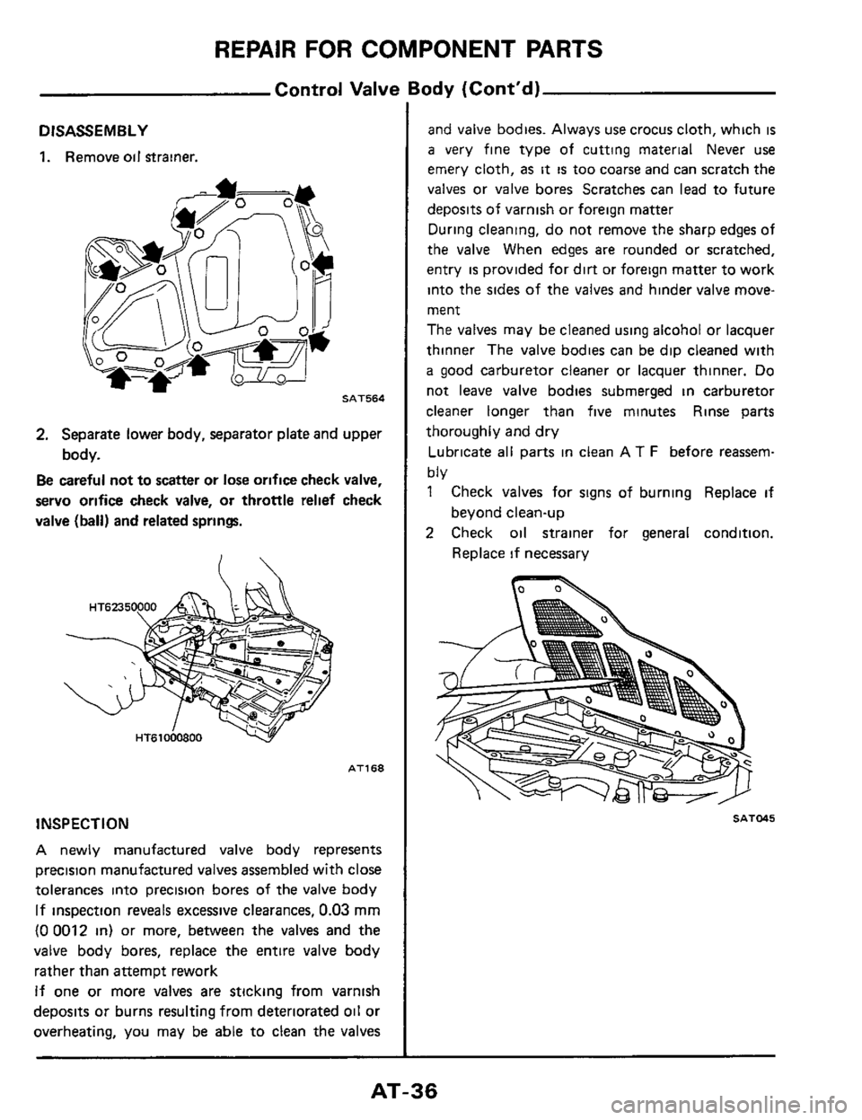
1. Remove oil Strainer.
SAT564
2. Separate lower body, separator plate and upper
body.
Be careful not to scatter or lose orifice check valve,
servo orifice check valve, or throttle relief check
valve (ball)
and related spring.
AT168
INSPECTION
A newly manufactured valve body represents
precision manufactured valves assembled with close
tolerances into precision bores of the valve body
If inspection reveals excessive clearances, 0.03 mm
(0 0012 in) or more, between the valves and the
valve body bores, replace the entire valve body
rather than attempt rework
If one or more valves are sticking from varnish
deposits or burns resulting from deteriorated oil or
overheating, you may be able to clean the valves
and valve bodies. Always use crocus cloth, which is
a very fine type of cutting material Never use
emery cloth,
as it is too coarse and can scratch the
valves or valve bores Scratches can lead to future
deposits of varnish or foreign matter
During cleaning, do not remove the sharp edges of
the valve When
edges are rounded or scratched,
entry
is provided for dirt or foreign matter to work
into the sides
of the valves and hinder valve move-
ment
The valves may be cleaned using alcohol or lacquer
thinner The valve bodies can be dip cleaned with
a good carburetor cleaner or lacquer thinner. Do
not leave valve bodies submerged in carburetor
cleaner longer than five minutes Rinse parts
thoroughly
and dry
Lubricate
all parts in clean AT F before reassem-
bly
1 Check valves for signs of burning Replace if
2 Check oil strainer for general condition.
beyond clean-up
Replace
if necessary
SATMS
AT-36
Page 37 of 99
REPAIR FOR COMPONENT PARTS
Control Valve Body (Cont’d)
3 Check separator plate for scratches or damage
Replace if necessary Scratches or score marks
can cause oil to by-pass correct oil passages
and result in system malfunction
SAT046
4. Check oil passages in upper and lower valve
bodies for varnish deposits, scratches or other
damage that would impair valve movement.
Check threaded holes and related bolts and
screws for stripped threads, replace
as needed
Test valve springs for weakened load condition
Refer to Valve Body Spring Chart for spring
specifications.
5
ASSEMBLY
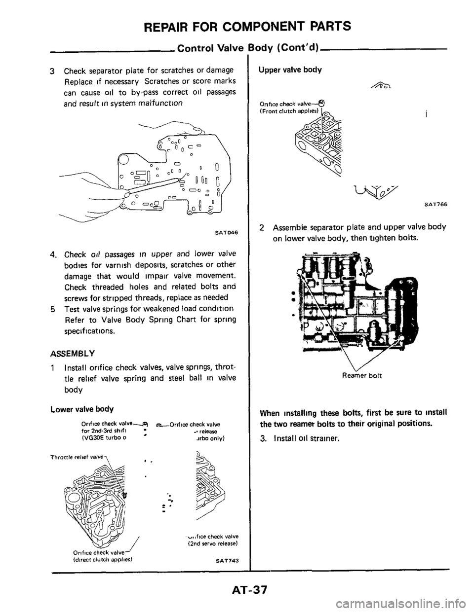
1 Install orifice check valves, valve springs, throt-
tle relief valve spring and steel ball in valve
body
Lower valve body
Orifice check Valve-P for 2nd-3rd rhifl .. reiea* (VG30E turbo (I a xbo only)
-oroftee check valve
Throttle relief valve,
Orifice chkk valveJ (direct clutch applies) SAT743
Upper valve body
A
Onfice check valve--@ (Front clutch applies) h
2 Assemble separator plate and upper valve body
on lower valve body, then tighten bolts.
ReaGer bolt
When installing these bolts, first be sure to install
the two reamer bolts to their original positions.
3. Install oil strainer.
AT-37
Page 59 of 99
ASSEMBLY
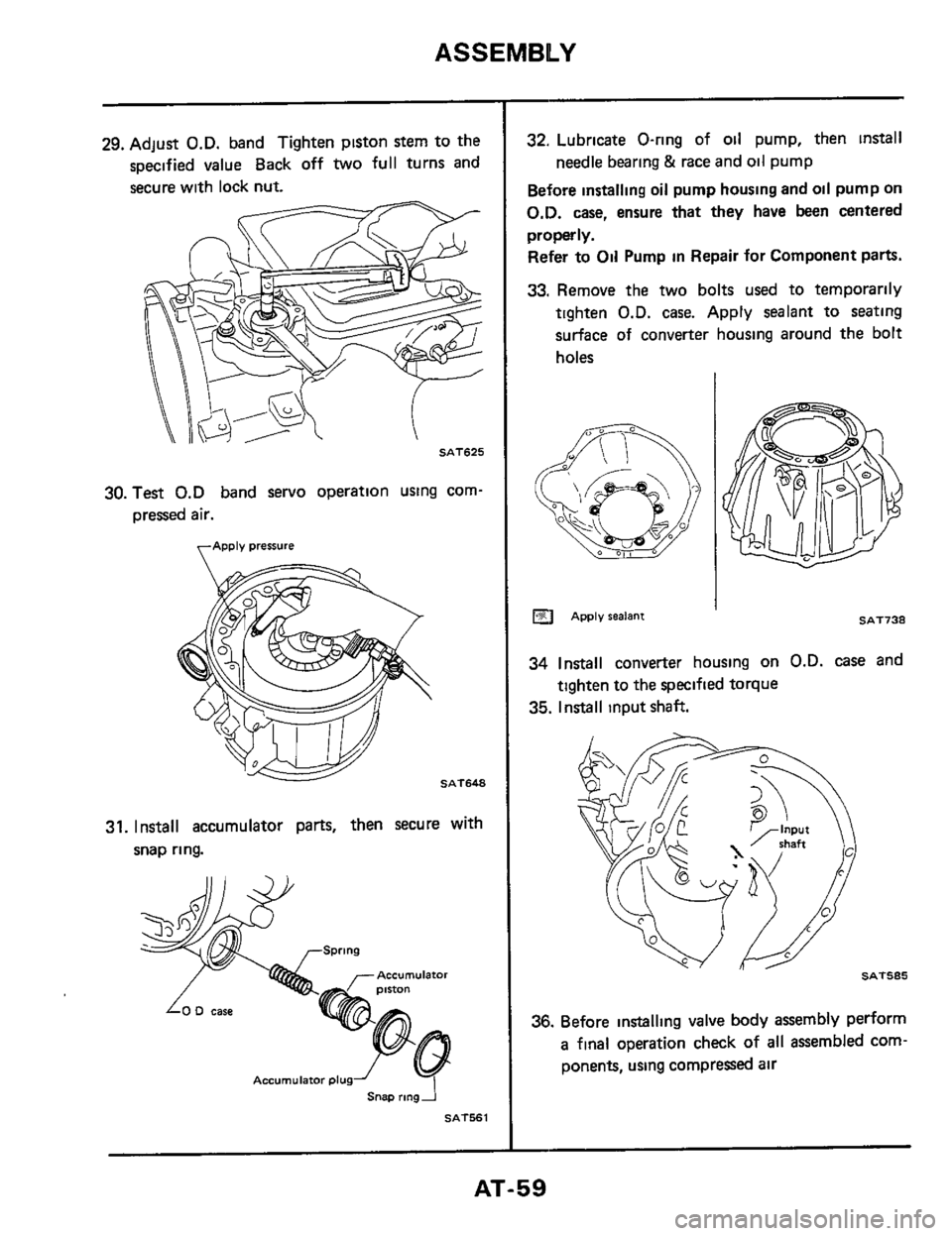
29. Adjust O.D. band Tighten piston stem to the
specified value Back off
two full turns and
secure with lock nut.
SAT625
30. Test 0.D band servo operation using corn-
pressed air.
apply pressure
SAT648
31. Install accumulator parts, then secure with
snap ring.
ACCUmUlafOr
Accumulator plug
Snap rmgi
SAT561
32. Lubricate O-ring of oil pump, then install
Before installing oil pump housing and oil pump on
O.D. case, ensure that they have been centered
properly.
Refer to Oil Pump in Repair for Component parts.
33. Remove the two bolts used to temporarily
tighten
O.D. case. Apply sealant to seating
surface
of converter housing around the bolt
holes
needle bearing & race and oil pump
APPIV sealant SAT738
34 Install converter housing on O.D. case and
35. Install input shaft.
tighten to the specified torque
.. SAT585
36. Before installlng valve body assembly perform
a final operation check of all assembled com-
ponents, using compressed air
AT-59
Page 60 of 99
ASSEMBLY
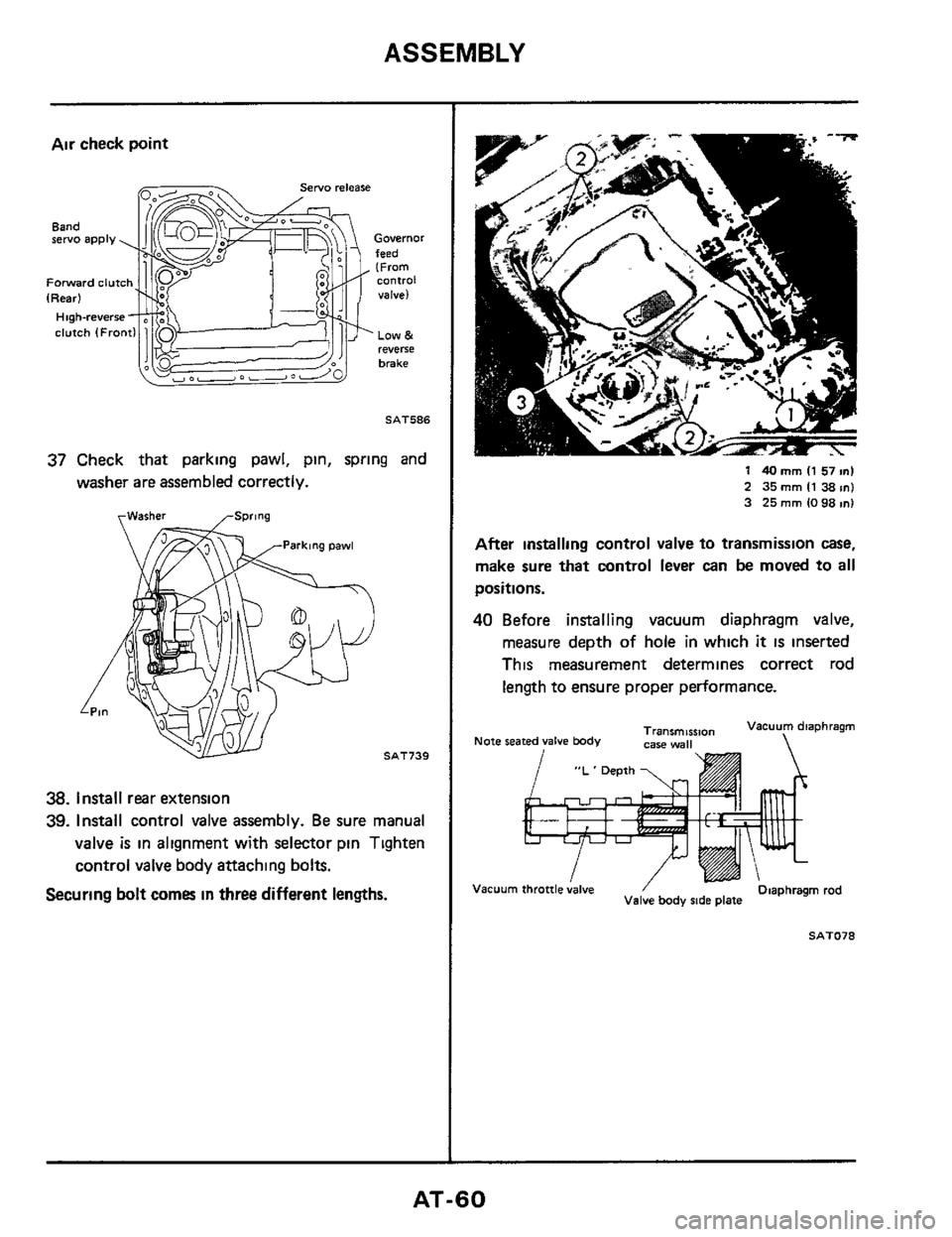
Air check point
Governor feed (From
valve) Forward clutch Control
LOW & reverse
brake
SAT586
37 Check that parking pawl, pin, spring and
washer are assembled correctly.
rWasher
SAT739
38. Install rear extension
39. Install control valve assembly. Be sure manual
valve
is in alignment with selector pin Tighten
control valve
body attaching bolts.
Securing bolt comes in three different lengths.
1 40 mm I1 57 ml
2 35 mm I1 38 m) 3 25 mm IO 98 1n1
After installing control valve to transmission case,
make sure that control lever can be moved to all
positions.
40 Before installing vacuum diaphragm valve,
measure depth of hole in which
it is inserted
This measurement determines correct rod
length to ensure proper performance.
"L ' Depth
Vacuum Diaphragm rod , throttle;alve / Valve body ride plate
AT-60
Page 92 of 99
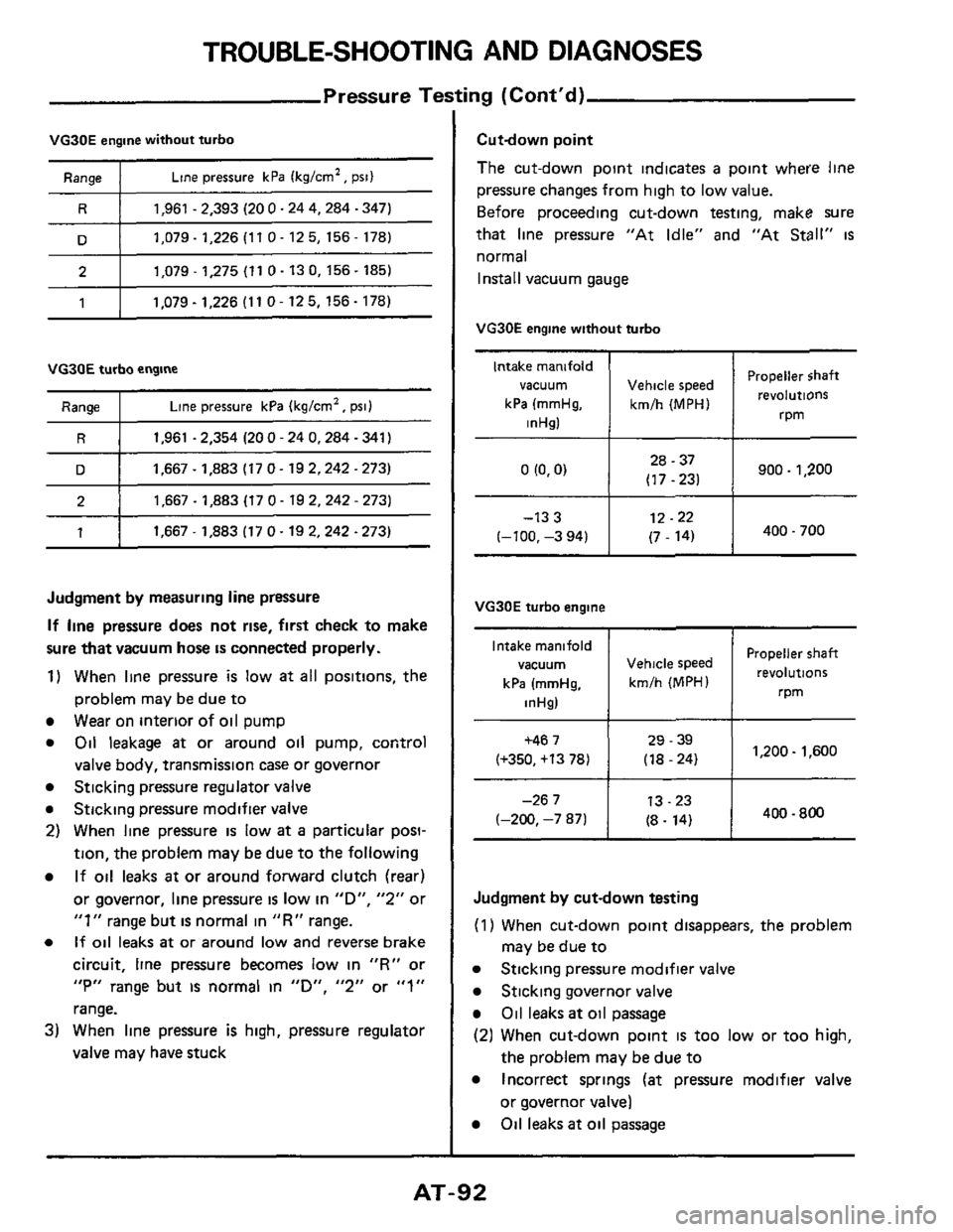
TROUBLE-SHOOTING AND DIAGNOSES
Pressure Testing (Cont'd)
Intake manifold
vacuum
kPa (mmHg,
inHsl
VG30E engine without turbo
Propeller $haft
Vehicle speed revolutions
kmlh (MPH)
rpm
Range I Line pressure kPa (kglcm', psi)
Intake manifold
vacuum
kPa (mrnHg.
inHg) ~
R I 1,961 - 2,393
(20 0.24 4,284 .347)
Propeller shaft Vehicle speed
kmlh (MPH) revolutions
rpm
D I 1.079-1,226(110-125,156-178)
2 I 1,079 - 1,275 (11 0.13 0, 156 - 185)
1 I 1,079 - 1,226 (1 1 0 - 12 5, 156 - 178)
VG30E turbo engine
Range I Line pressure kPa (kgtcm', psi)
R I 1,961 - 2,354 (20 0 - 24 0,284 - 341)
D I 1,667 - 1,883 (17 0- 19 2,242 -273)
2 I 1.667-1,883(170-192,242-273)
1 I 1.667-1.8831170-192.242-273)
Judgment by measuring line pressure
If line pressure does not rise, first check to make
sure that vacuum
hose is connected properly.
1) When line pressure is low at all positions, the
problem may be due to
Wear on interior of oil pump
Oil leakage at or around oil pump, control
valve body, transmission case or governor
Sticking pressure regulator valve
Sticking pressure modifier valve
2) When line pressure is low at a particular posi-
tion, the problem may be due to the following
If oil leaks at or around forward clutch (rear)
or governor, line pressure
is low in "D", "2" or
"1" range but is normal in "R" range.
If oil leaks at or around low and reverse brake
circuit, line pressure becomes low in
"R" or
"P" range but IS normal in "D", "2" or "1"
range.
3) When line pressure is high, pressure regulator
valve may have stuck
Cutdown point
The cut-down point indicates
a point where line
pressure changes from high to low value.
Before proceeding cut-down testing, make sure
that line pressure "At Idle" and "At
Stall'' is
normal
Install vacuum gauge
VG30E engine without turbo
28 - 37
o(o'o) I (17-231 I 900- 1,200
12.22
(7 - 14) I 400-700 (-100. -133 -3 94) I
VG30E turbo engine
+467 I 29 - 39 1,200- 1,600 (+350, +13 78) (18 - 24)
13.23
(-200,
-267 -7 871 I (8. 14) 400 - 800
Judgment by cut-down testing
(1) When cut-down point disappears, the problem
Sticking pressure modifier valve
Sticking governor valve
Oil leaks at oil passage
(2) When cut-down point is too low or too high,
the problem may be due to
Incorrect springs (at pressure modifier valve
or governor valve)
Oil leaks at oil passage
may be due to
AT-92
Page 98 of 99
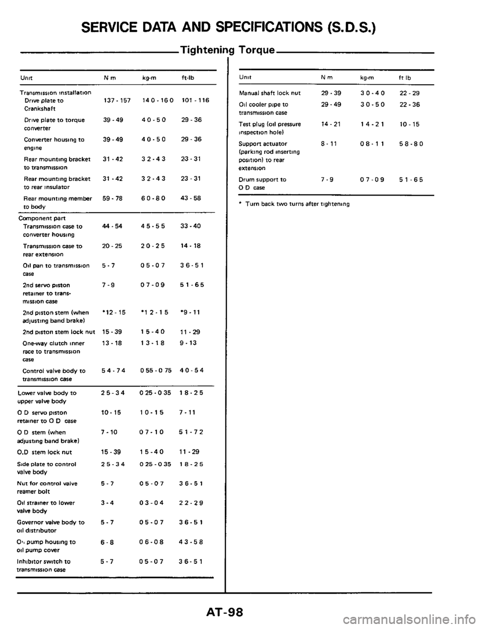
SERVICE DATA AND SPECIFICATIONS (S.D.S.)
Tig hteni
Untt Nm kg-m ft-lb
Transmission mrtallation Drive plate to 137-157 140-160 101.116
Crankshaft
Drive plate to torque 39.49 4 0.5 0 29.36
converter
Converter housing to
39 - 49 4 0 - 5 0 29 - 36
engme
Rearmountingbracket
31 -42 32-43 23-31
to transmissnon
Rear mounting bracket
31 -42 3 2 - 4 3 23 - 31
to rear insulator
Rear mounting
member 59 - 78 6 0.8 0 43.58
to body
Camponent part
Transmission case to
converter housing
Transmission
case IO
rear extension
Od pan to transmissJon
case
2nd servo piston
retainer to trans- mission case
2nd piston stem (when adjusting band brake)
2nd mston stem lock nut
Onway clutch inner
race to transmission
Control valve body to
transmission case
Wle
44.54
20.25
5-7
7-9
'12-15
15-39
13-18
54-74
45-55 33-40
20-25 14-18
05-07 36-51
07-09 51-65
'12-15 *9.11
15-40 11-29
13-18 9-13
055-075 40-54
Lower valve body to 25-34 025-035 18-25
upper valve body
0 D servo pinon 10- 15 10-15 7-11
retainer to 0 D case
0 D stem (when 7-10 07-10 51-72
adjusting band brake)
0.D stem lock nut 15-39 15-40 11-29
Side Plate to Control 25-34 025-035 18-25 valve body
Nut for control valve 5-7 05-07 36-51
reamer bolt
011 strainer to lower 3-4 03-04 22-29
valve body
Governor MIM body to 5 - 7 05-07 36-51
011 distrtbutor
O*, pump housing to 6-8 06-08 43-58 011 pump cover
Inhibitor switch
to 5-7 05-07 36-51
transmission case
I Torque
U"lt Nm kgm ft Ib
Manual shaft lock nut 29.39 30-40 22-29
011 cooler pipe to 29 - 49 30-50 22-36 transmission case
Test plug
lo11 pressure 14-21 14-21 10-15 inspection hole)
Support actuator 8- 11 08-11 58-80
(parking rod inserting
position) to
rear
extension
Drum support to 7-9 07-09 51-65 0 D case
* Turn back two turns after tightening