1984 CHEVROLET CAVALIER towing
[x] Cancel search: towingPage 6 of 105
Downloaded from www.Manualslib.com manuals search engine SECTION 1
BEFORE DRIVING YOUR CAVALIER
TRANSAXLE
While reading this manual, you will nole many references 10 Ihe "transaxle." The transaxle is a transmission and differential (axle) combined in a singl ,e unit.
To avoid confusion, the word
"transaxle" will be used throughout this manual 10 refer to bolh Ihe transmission and differenlial funclions.
DRIVER DAILY CHECKUST
Be sure you know how to use your vehicle and its equipment before operating it
Before Entering the Vehicle
1. See that windows, mirrors and lights are clean and unobstructed.
2. If any lire does not look normal, check it with a pressure gage.
3. Look for fluid leaks .
4. Be sure everything is properly stowed.
5. Check the area behind the vehicle if you are about to back up.
__ Before Driving Off
1. Lock all doors.
2. Adjust the seat and any movable head restraint
3. Adjust inside and outside mirrors.
4. DO NOT allow anyone to ride where there is no seat belt ; and ALWAYS properly fasten the seat belt.
5. Check that all the warning lights work as the key is turned to "Run" or "Start"
6. Check all gages (including the fuel gage).
7 . Release the parking brake (and make sure the
"BRAKE " light turns .off).
See related topics in this manual
or the Maintenance Schedule folder H problems are found.
STOWING THINGS IN (OR ON) THE VEHICLE
CAUTION: Put luggage or cargo In the trunk, or rea' area if postible. Cargo weight,
whether In the trunk or rear area, should be located as far forward as possible. Cargo weight on the roof Shoukt be positioned .s evenly as possible. Secure all i1ems in place to help keep them -from being thrown about and injuring people during a cot"-ion or sudden maneuver. Do not pile luggage or cargo higher than the seetbaCks. Do not place anything on the filler panel, or any cargo cover between the rear seat~.ck and window.
GUARD AGAINST THEFT
Your new Cava~er has many features to help prevent then of the vehicle, its
equipment, and contents. But these anti-then features
depend upon you to work.
t -1
Page 18 of 105
Downloaded from www.Manualslib.com manuals search engine Driving with the trunk lid, hatchback or liftgate on station wagon models open is not recommended. Under some conditions, exhaust gases may be drawn
into the vehicle. If the trunk lid, hatchback or liftback must remain open for
some reason while moving, or if electrical wiring or other cable connections to a trailer must pass through the seal between the trunk lid, hatchback or liftback
and the body, follow these precautions:
• Close all windows.
• Adjust the heating or cooling system to force outside air into the vehicle as
described abcve, but set the fan to high speed.
• On vehicles with outside air vents in or under the instrument panel, open the vents fully.
NEW VEHICLE "BREAK-IN" PERIOD
You can drive your new vehicle from its very first mile/kilometer without
following a formal "break-in" schedule. However, there are things you can do during the first few hundred miles/kilometers of driving that will add to the
future performance and economy of your vehicle.
We recommend you limit your speed during the first 500 miles (800 kilometers)
to a maximum of 55 mph (90 km/h); but do not drive for long periods at any
one constant speed, either fast or slow. During this time, avoid full throttle
starts and, if possible, avoid hard stops especially during the first 200 miles (320 kilometers) of driving.
Always drive at moderate speed until the engine has completely warmed up.
I! you plan to use your new vehicle for trailer towing, see the following.
TRAILER TOWING
This car is designed and intended to be used mainly to carry people. Towing a
trailer
will affect handling, durability and economy. Your safety and satisfaction
depend upon proper use of correct equipment. Also, you should avoid
overloads and other abusive use.
The maximum loaded trailer weight you can pull with your vehicle depends on
your intended use
and what special equipment has been installed on it.
Information on trailer towing ability, special equipment required, and optional
equipment available should be obtained from your dealer. Ask for the trailering brochure. Or, write: Consumer Relations Department, Chevrolet Motor
Division, Warren, Michigan 48090.
(In Canada, write to General Motors of
Canada Limited, Customer Services Department, Oshawa, Ontario L lJ 5Z6.)
Tires
When towing trailers, be sure your tires are properly inflated to the inflation pressure shown on the Tire Placard on the driver's door.
The allowable passenger and cargo load for this vehicle, also shown on the
Tire
Placard, is reduced by the trailer tongue weight whenever the trailer is
attached to the vehicle. See "Service and Maintenance," Section 5 for more tire information.
Maintenance
More frequent service is required when using your vehicle to pull a trailer. See
the Maintenance Schedule folder for Automatic Transaxle Fluid and Engine Oil change requirements for trailering.
2-2
Page 19 of 105
Downloaded from www.Manualslib.com manuals search engine Now and then, check that all trailer hitch bolts and nuts are tight. Also see the
Maintenance
Schedule folder, and thelndax in this manual , for important facts
on
belts , cooling system care and brake ~tment.
Break-In Schedule
See the new vehicle break-in information in this manual. Also, we recommend
you drive your new vehicle for 500 miles (800 kilometers) before trailer towing.
At the end of this 500 mile (800 kilometer) break-in period, avoid speeds over
50 mph (80 km/h) and full throttle starts during the first 500 miles (800 kilometers) of trailer towing .
CAUTION:
BRAKES-To help avoid personal injury due to poor braking action :
•
Trailer brakes of adequate size are required on trailers more than 450
kilograms (1,000 pounds) loaded weight.
• If you use trailer brakes with this vehicle, follow the instailation and balance instructions of the trailer brake manufacturer.
• Do not tap into the vehicle's brake system iUhe trailer brake system uses
more than 0.3 cubic centimeter (0.02 cubic inches) 01 fluid from the
vehicle 's
mast.". cyllnd<1r .. , In this case, the vehicle's brake fluid capacity will not be enough to operate both thevehicte and trailer brakes under all kinds
of use.
• All brake fluid parts must be able to stand 20 650 kPa (3,000 psi) . The
brake fluid tap must be made at the upper rear master cylinder port.
Copper tubing is subject to fatigue failure and must not be used.
HITCHES-To help avoid personal injury due to sway caused by such things as
crosswinds, large trucks passing or road roughness , or due to separation of
the trailer :
• A properly installed and adjusted (1) frame mounted, weight-dstribut ing hitch and (2) sway control witheoough capacity are required for trailers
more than 900 kilograms (2,000 pounds) loaded weight.
• Keep the trailer tongue load at 10 percent of the loaded trailer weight for
dead-weight hitches and 12 percent for weight-distributing hitches. Tongue
loads can be adjusted by proper distribution of the load in the trailer. This
can
be checked by weighing separately the loaded trailer and then the
tongue .
• Do not use axle-mounted Mches. They can damage the axle housing , wheel bearings , wheels or tires.
• Do not allow steel hitch parts to be in direct contact with aluminum bumper
parts, if so equipped. When steel and aluminum are in contact, a galvanic
reaction (a form of corrosion) can occur which will progressively lessen the
strength of the contacting metals to the point
of failure. An organic
compound or paint should
be used as a barrier on the contacting surfaces
and on the attaching fasteners.
• When you remove a trailer hitch, be sure to seal any mounting holes in the body. This will help prevent entry 01 exhaust fumes,
"Starting and Operating ," Section 2 ollhis manual.)
2-3
Page 20 of 105
Downloaded from www.Manualslib.com manuals search engine NonCE: Use only trailer hitches which permit normal operation of the Energy
Absorbing Bumper system, If so equipped. For example, a rigid fore and aft connection between the bumper and any other part of-the vehicle may increase damage in the event of a collision.
TRAILER TOWING TIPS
Getting Started
Before entering traffic with a trailer that has electric brakes, start the vehicle and trailer moving and apply the trailer brakes by hand to be sure the trailer
brakes are working and the trailer electrical system is connected.
Engine Cooling
If your engine overheats, follow the steps under "Engine Cooling System
Overheating" in "In Case of Emergency," Section 3 of this manual.
Long Uphill Grades
When going up long grades, you can reduce the chance 01 engine overheating
by turning off the air conditioner, if so equipped.
Down Steep Or Long Grades
Before going down a steep or long grade, reduce speed and shift the transaxle
into a lower gear to help control your vehicle's speed. Try not to hold the brake pedal down too long or too often. This could cause the brakes to overheat and
reduce brake effectiveness.
Transaxle
See the method for checking the transaxle fluid level in "Service and
Maintenance,"
Section 5 of this manual.
Parkin!!
You should not park vehicles with trailers on a grade (hill). However, if you
must park on a grade, these steps must be followed:
1. Apply the regular brakes.
2. Have someone place wheel chocks under the trailer wheels.
3. When the wheel chocks are in place, release the regular brakes until the
chocks absorb the load.
4. Apply the parking brake.
5. Shift the transaxle to "P"(Park),
If the vehicle is parked on a grade, don't shift the transaxle to "P"(Park) until the trailer wheels are chocked and the parking brake is set. If you do, the
weight of the
vehicle and trailer may put so much force on the parking pawl in
the transaxle that it may be hard to shift out of "P"(Park).
When starting, after being parked
on a grade:
1. Apply the regular brakes and hold.
2. Start the engine in "P"(Park).
3. Shift into gear and release the parking brake.
4. Release the regular brakes and drive until the chocks are free.
5. Apply the regular brakes and have someone remove the chocks.
2·4
Page 25 of 105
Downloaded from www.Manualslib.com manuals search engine • Lane Change Signal -In some turns, such as changing lanes, the steering wheel tS not turned far enough to cancel the turn signal. For convenience, you can flash the turn signal by moving the lever part way (to the first stop)
and holding it there. The lever will return to horizontal when you release it.
A green light on the instrument panel is designed to flash to tell you that the
front
and rear turn signal lights are working. If the light stays on, but does not flash, check for burned-out turn signal bulbs. If the green light does not come
on when
you move the lever, check the fuse and indicator bulb.
However, if you ordered a trailertowing·optiOil.·in which extra wiring was added to attach the trailer lighting, a different type of flasher was installed. In this
case, the green light will continue to flash even if a turn signal bulb burns out.
Therefore, you must regularly look at the front
and rear turn signal lights to be
sure they are working.
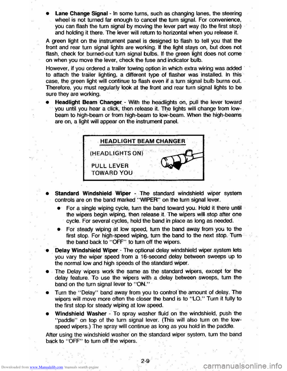
• Headlight Beam Changer -With the headlights on, pull the lever toward you until you hear a click, then release it. The lights will change from Iow
beam to high-beam or from high-beam to low-beam. When the high-beams
are
on, a light will appear on the instrument panel.
HEADLIGHT BEAM CHANGER
(HEADLIGHTS ON)
PULL LEVER
TOWARD YOU
• Standard Windshield Wiper -The standard Windshield wiper system
con
ols are on the band marked "WIPER" on the turn signal lever.
• For a single wiping cycle, turn the band toward you. Hold it there until
the wipers begin
Wiping, then release.it. The wipers will stop after one
cycle. For several cycles, hold the band in place as long as needed.
• For steady wiping at low speed, turn the band away from you to the
first stop. For high-speed wiping, turn the band to the next stop. Turn
the band back to
"OFF" to turn off the wipers.
• Delay Windshield Wiper -The optional delay windshield wiper system lets you vary the wiper speed from a 16-second delay between sweeps up to
the normal
low and high speeds of the standard wiper.
• The Delay wipers work the same as the standard wipers, except for the
delay feature. To use the wipers with a delay between sweeps, turn the
band on the turn signal lever to
"ON."
• Turn the "Delay" band away from you to control the amount of delay. The
wipers will move more often the closer the band is to "LO." Turn it fully to
the first stop for steady wiping at
low speed.
• Windshield Washer -To spray washer fluid on the windshield, pUSh the "paddle" on top of the turn signal lever. (This will also turn on the low~ speed wipers.) The spray will continue as long as you hold in the paddle.
After using the windshield washer
on the standard wiper system, turn the band
back to "OFF" to turn off the wipers.
2-9
Page 28 of 105
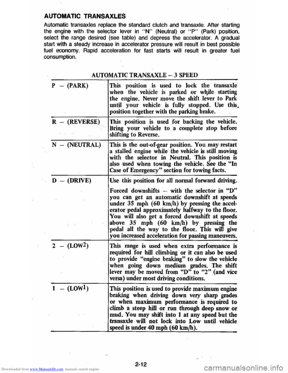
Downloaded from www.Manualslib.com manuals search engine AUTOMATIC TRANSAXLES
Automatic Iransaxles replace the standard clutch and Iransaxle . After starting
the engine with the selector lever in "N" (Neutral) or "P" (Park) posnion,
select the range desired (see table) and depress the accelerator. A gradual start with a steady increase in ac ce lerator pressure will result in best possible
fuel economy. Rapid acceleration for fast starts will result in greater fuel consumption.
P -(PARK)
AUTOMATIC TRANSAXLE - 3 SPEED
This position is used to lock the transaxle
when the vehicle
is parked or wlVle starting
the engine. Never move the shift
lever to Park
until your vehicle is fully stopped . Use this.
position together with the parking brake.
R - (REVERSE) This position
is used fot backing the vehicle.
" Bring your vehicle to a complete stop before
shifting to Reverse .
N - (NEUTRAL)
This is the out-of.gear position. You may restart
a stalled engine while the vehicle
is still moving
with the selector
"in Neutral. This position is also used when towing the vehicle. See the "In Case of Emergency" section for towing facts.
D
- " (DRIVE) Use this position for all normal forward driving.
Forced downshifts -with the selector in "D"
you can get an automatic downshift at speeds
under
3S mph (60 km/h) by pressing Ihe accel· erator pedal approximately halfway to the 1I00r.
You
will also get a forced downshift at speeds
above 35 mph
(60 km/h) by pressing the
pedal all the way to the 1I00r . This will give
you increased acceleration for passing maneuvers.
2 - (LOW2) This range is used when extra performance is
required for hill climbing or it can also be used to provide "engine braking" to slow the vehicle
when going down medium grades. The shift lever may'be moved from "D" to "2n(and vice
versa) under most driving conditions.
1 - (LOWl) This position
is used to provide maximum engine
braking
when driving down very sharp grades
or when maximum performance is required
to
climb a steep hill or run through deep snow or
mud. You may shift into 1 at any speed but the
transaxle " will not lock into Low until vehicle
speed
is under 40 mphl.60 km/h).
2-12
Page 34 of 105
Downloaded from www.Manualslib.com manuals search engine When_ going up or down hills. it ~ ~ tor the vehk:1e to toM 011 to gain apHCI (.,.rticu"Y when towing I trailer), even though the Cruise Control is enpgecL • this happens while going up hin, merely depress the accelerator pedal to maintain the speed desired. If going down a hili steep enough to cau .. thl vehie'" to gain speed, depress the brake pedal •• which will both dl .. ngage the Cruise Control and help .lOw the vehicle. In addition, when going down a steep or lang grade . the transaxle shoUld be shifted into I lower gear to help control vehicte speed •• see "Descending A Grade " in "Starting and Operating," Section 2.
HORN
The horn on your vehicle is actuated by firmly pressing on the ped in the
center of the steering
wheel.
HAZARD WARNING FLASHER
The hazard warning flasher is covered in "In Case of Emergency," Section 3.
FLOOR CONTROLS
BRAKING SYSTEM
The regular braking system is designed for braking performance under a wide
range of driving cond~ions even when the vehicle is loaded to ~ lull rated
vehicle toad capacity .
CAUTION: Driving through water deep enough to wet brake components may cau .. the brakea nat to work .. welL -M a reaul, the vehIde wi. not aIow down .. the usu.I _, ond M may pull 10 "'" right Of ..... _ 0"'-""'11 to "'" _ tor _ .-.os,
-'1 "'" ...... lightly 10 check __ .... "-'"
Brake Warning lJg/rt
The brake system warning light is covered in the '.' lnstrumentPanel" section.
Vacuum Power Brakes
• the engine stops, do not pump the brakes. The system is designed to stop the vehicle with reserve power assist n the brake pedal is held dOwn. This
reserve is
greatly reduced each time you apply and release the brakes. II,
when you turn the atMring wheel during braking, the vehic:1e does not turn, don't push as hard on the brake pedal •.
Without power assist the vehicle can still be stopped by pushing much harder
on the brake
pedal. however. the stopping distance may be longer.
Brakes (Except ,Parking Brake)
H the brake pedaJ goes down farther than normal, ~ may be due to a lack of
adjustment of any rear drum
brakes. To find. out if this is the case. drive
backward and forward a few times. applying the brakes firmly when going in
each direction.
See your dealer n pedal height dOes not retum to normal, or there is a rapid
increase in pedal travel whether or not your vehicle has rear drum brakes. This
could be a sign of brake trOUble.
NOTICE: "FtidInsI the brake" by resting yow i0oi on thl brau pedal when you do not Intend 'to brake CIIf1 overhMI: the brIkM and ...... out the brake InInga and p..ts faster. , ThI. mIIy alSo dllNlge the brakes Mtd will wasta fuel.
2-18
Page 38 of 105
Downloaded from www.Manualslib.com manuals search engine Have the system repaired n the "CHECK ENGINE" light does not come on during engine starting. If the light comes on, either intermittently or
continuously while driving, service to the Computer Command Control system
is required. AHhough in most cases the vehicle is drivable, and does not
require towing, see your authorized
dealer as soon as possible for service of
the system.
Continued driving without having the Computer
Command Control system serviced could cause damage to the emission control system. It could also affect fuel economy and drivability.
See also "Computer Command Control system" in Section 5 of this manual.
Brake System Warning Light
The regular braking system is a dual system designed so that one part will
provide some braking if there is a
loss of hydraulic pressure in the other part of
the system. The system has a
"BRAKE" warning light located in the
instrument panel. The "BRAKE" light is designed to come on briefly during
engine starting so you can check that the bulb is okay. To serve as a reminder,
the
light should stay on when the parking brake is not fully released and the
ignition is
on. Have the system repaired if the light does not come on when it should. This warning light does not do away with the need for brake inspection
and maintenaflce. The brakelluid level must be checked regularly. See your
Maintenance Schedule folder for other brake checks.
I! the light remains on aller engine start up or comes on during operation of the vehicle, it may mean that there is something wrong with part of the brake
system.
What
to do:
1. Check to see that the parking brake has been released. I! it has been:
2. Pull off the road and stop carefully. Remember that:
• Stopping distances may be longer.
•
You may have to push harder on the pedal.
•
The pedal may go down farther than normal.
3. Tryout the brakes by starting and stopping on the road shoulder--then:
• I! you judge it to be safe, drive cautiously at a safe speed to the
nearest dealer for repair. Or,
• Have vehicle towed to the nearest dealer for repair.
Continued driving without getting necessary repairs
could be dangerous.
Tachometer
The optional tachometer indicates the speed of the engine in revolutions per
minute. The indicated number, times
100, gives the engine speed. Operating
the engine with the tachometer reading in the color-coded high-speed area
could lead to serious engine damage.
Voltmeter
When the engine is operating, the voltmeter indicates the electrical system
voltage. During minimum electrical load, the pointer will read to the right of the
center.
As the electrical load is increased, or in stop-and-go driving, the pointer
will rotate to the Ieli. A meter reading continuously in the left or right zone
indicates
an electrical system failure. Cause of the failure should be determined and corrected.
2-22