1983 FIAT UNO timing belt
[x] Cancel search: timing beltPage 132 of 303

Supplement: Revisions and information on later models 13•7
View of engine compartment (air
cleaner removed) on the
1372 cc ie engined model
1 Engine oil level dipstick
2 Timing belt cover
3 Engine mounting (right-hand)
4 Clutch master cylinder fluid
reservoir
5 Fuel supply and return hoses
6 Injection unit
7 Inlet manifold
8 Washer reservoir
9 Brake master cylinder and fluid
reservoir
10 Injection system fuse/relay block
11 Suspension strut turret
12 Ignition coil
13 Ignition system ECU
14 Battery
15 Coolant filter expansion tank
16 Ignition distributor
17 Radiator cooling fan
18 Engine oil filler cap
19 Starter motor
20 Oil filter
View of front end from below on
the 1031 cc Turbo ie engined
model
1 Anti-roll bar
2 Exhaust pipe
3 Track control arm
4 Engine centre mounting
5 Gearchange rods
6 Brake caliper
7 Left-hand driveshaft
8 Intermediate driveshaft
9 Right-hand driveshaft
10 Transmission
11 Engine oil drain plug
12 Auxiliary lamp
13 Horn
14 Intercooler
15 Starter motor
16 Oil filter cartridge
17 Oil pressure sender unit
18 Engine oil cooler
19 Right-hand underwing shield
20 Left-hand underwing shield
13
Page 134 of 303
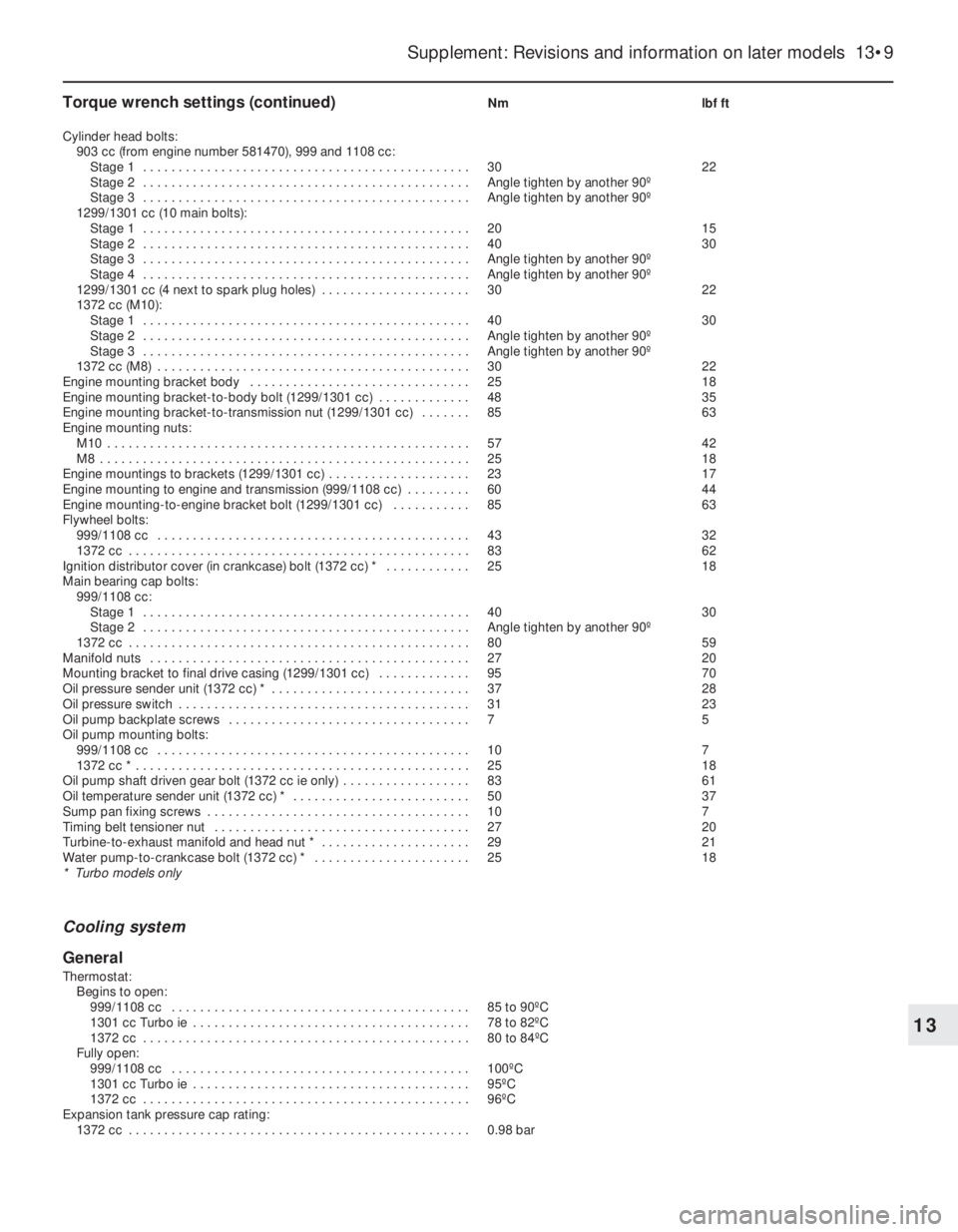
Torque wrench settings (continued)Nm lbf ft
Cylinder head bolts:
903 cc (from engine number 581470), 999 and 1108 cc:
Stage 1 . . . . . . . . . . . . . . . . . . . . . . . . . . . . . . . . . . . . . . . . . . . . . . 30 22
Stage 2 . . . . . . . . . . . . . . . . . . . . . . . . . . . . . . . . . . . . . . . . . . . . . . Angle tighten by another 90º
Stage 3 . . . . . . . . . . . . . . . . . . . . . . . . . . . . . . . . . . . . . . . . . . . . . . Angle tighten by another 90º
1299/1301 cc (10 main bolts):
Stage 1 . . . . . . . . . . . . . . . . . . . . . . . . . . . . . . . . . . . . . . . . . . . . . . 20 15
Stage 2 . . . . . . . . . . . . . . . . . . . . . . . . . . . . . . . . . . . . . . . . . . . . . . 40 30
Stage 3 . . . . . . . . . . . . . . . . . . . . . . . . . . . . . . . . . . . . . . . . . . . . . . Angle tighten by another 90º
Stage 4 . . . . . . . . . . . . . . . . . . . . . . . . . . . . . . . . . . . . . . . . . . . . . . Angle tighten by another 90º
1299/1301 cc (4 next to spark plug holes) . . . . . . . . . . . . . . . . . . . . . 30 22
1372 cc (M10):
Stage 1 . . . . . . . . . . . . . . . . . . . . . . . . . . . . . . . . . . . . . . . . . . . . . . 40 30
Stage 2 . . . . . . . . . . . . . . . . . . . . . . . . . . . . . . . . . . . . . . . . . . . . . . Angle tighten by another 90º
Stage 3 . . . . . . . . . . . . . . . . . . . . . . . . . . . . . . . . . . . . . . . . . . . . . . Angle tighten by another 90º
1372 cc (M8) . . . . . . . . . . . . . . . . . . . . . . . . . . . . . . . . . . . . . . . . . . . . 30 22
Engine mounting bracket body . . . . . . . . . . . . . . . . . . . . . . . . . . . . . . . 25 18
Engine mounting bracket-to-body bolt (1299/1301 cc) . . . . . . . . . . . . . 48 35
Engine mounting bracket-to-transmission nut (1299/1301 cc) . . . . . . . 85 63
Engine mounting nuts:
M10 . . . . . . . . . . . . . . . . . . . . . . . . . . . . . . . . . . . . . . . . . . . . . . . . . . . 57 42
M8 . . . . . . . . . . . . . . . . . . . . . . . . . . . . . . . . . . . . . . . . . . . . . . . . . . . . 25 18
Engine mountings to brackets (1299/1301 cc) . . . . . . . . . . . . . . . . . . . . 23 17
Engine mounting to engine and transmission (999/1108 cc) . . . . . . . . . 60 44
Engine mounting-to-engine bracket bolt (1299/1301 cc) . . . . . . . . . . . 85 63
Flywheel bolts:
999/1108 cc . . . . . . . . . . . . . . . . . . . . . . . . . . . . . . . . . . . . . . . . . . . . 43 32
1372 cc . . . . . . . . . . . . . . . . . . . . . . . . . . . . . . . . . . . . . . . . . . . . . . . . 83 62
Ignition distributor cover (in crankcase) bolt (1372 cc) * . . . . . . . . . . . . 25 18
Main bearing cap bolts:
999/1108 cc:
Stage 1 . . . . . . . . . . . . . . . . . . . . . . . . . . . . . . . . . . . . . . . . . . . . . . 40 30
Stage 2 . . . . . . . . . . . . . . . . . . . . . . . . . . . . . . . . . . . . . . . . . . . . . . Angle tighten by another 90º
1372 cc . . . . . . . . . . . . . . . . . . . . . . . . . . . . . . . . . . . . . . . . . . . . . . . . 80 59
Manifold nuts . . . . . . . . . . . . . . . . . . . . . . . . . . . . . . . . . . . . . . . . . . . . . 27 20
Mounting bracket to final drive casing (1299/1301 cc) . . . . . . . . . . . . . 95 70
Oil pressure sender unit (1372 cc) * . . . . . . . . . . . . . . . . . . . . . . . . . . . . 37 28
Oil pressure switch . . . . . . . . . . . . . . . . . . . . . . . . . . . . . . . . . . . . . . . . . 31 23
Oil pump backplate screws . . . . . . . . . . . . . . . . . . . . . . . . . . . . . . . . . . 7 5
Oil pump mounting bolts:
999/1108 cc . . . . . . . . . . . . . . . . . . . . . . . . . . . . . . . . . . . . . . . . . . . . 10 7
1372 cc * . . . . . . . . . . . . . . . . . . . . . . . . . . . . . . . . . . . . . . . . . . . . . . . 25 18
Oil pump shaft driven gear bolt (1372 cc ie only) . . . . . . . . . . . . . . . . . . 83 61
Oil temperature sender unit (1372 cc) * . . . . . . . . . . . . . . . . . . . . . . . . . 50 37
Sump pan fixing screws . . . . . . . . . . . . . . . . . . . . . . . . . . . . . . . . . . . . . 10 7
Timing belt tensioner nut . . . . . . . . . . . . . . . . . . . . . . . . . . . . . . . . . . . . 27 20
Turbine-to-exhaust manifold and head nut * . . . . . . . . . . . . . . . . . . . . . 29 21
Water pump-to-crankcase bolt (1372 cc) * . . . . . . . . . . . . . . . . . . . . . . 25 18
* Turbo models only
Cooling system
General
Thermostat:
Begins to open:
999/1108 cc . . . . . . . . . . . . . . . . . . . . . . . . . . . . . . . . . . . . . . . . . . 85 to 90ºC
1301 cc Turbo ie . . . . . . . . . . . . . . . . . . . . . . . . . . . . . . . . . . . . . . . 78 to 82ºC
1372 cc . . . . . . . . . . . . . . . . . . . . . . . . . . . . . . . . . . . . . . . . . . . . . . 80 to 84ºC
Fully open:
999/1108 cc . . . . . . . . . . . . . . . . . . . . . . . . . . . . . . . . . . . . . . . . . . 100ºC
1301 cc Turbo ie . . . . . . . . . . . . . . . . . . . . . . . . . . . . . . . . . . . . . . . 95ºC
1372 cc . . . . . . . . . . . . . . . . . . . . . . . . . . . . . . . . . . . . . . . . . . . . . . 96ºC
Expansion tank pressure cap rating:
1372 cc . . . . . . . . . . . . . . . . . . . . . . . . . . . . . . . . . . . . . . . . . . . . . . . . 0.98 bar
Supplement: Revisions and information on later models 13•9
13
Page 143 of 303

13•18 Supplement: Revisions and information on later models
Every 9000 miles (15 000 km) or
12 months (whichever comes first)
m mCheck the tyre pressures and their condition
(including the spare)
m mWhere a pad wear warning light is fitted, check its
operation
m mCheck the front brake disc pads for excessive wear
m mCheck the underbody condition (fuel and brakes
pipes, exhaust system, hoses, bushes and gaiters)
m mCheck the condition and tension of drivebelts
m mCheck the engine idle speed and CO emissions
m mCheck the EGR system (If fitted)
m mCheck fluid levels (coolant, brake fluid and
windscreen washer)
m mRenew spark plugs (1372 cc Turbo models)
m mRenew the engine oil and oil filter (non-Turbo
models)
m mCheck the HT leads and connections
m mCheck the condition of all coolant, fuel and
hydraulic hoses and connections
Every 18 000 miles (30 000 km) or
24 months (whichever comes first)
In addition to the items listed for 9000 mile (15 000 km) or 12 months
service
m mCheck the rear brake disc pads for wear (where
applicable)
m mCheck/adjust the valve clearances
m mCheck and tighten (if necessary), inlet and exhaust
manifolds
m mCheck the clutch adjustment (cable operated
models)
m mRenew the fuel filter (where applicable)
m mRenew the air cleaner element
m mRenew the spark plugs and check the HT leads
and connections (all models)
m mWhere applicable, have the ignition and injection
systems checked (special equipment needed)
m mRenew coolant
m mRenew brake fluid
Every 28 000 miles (45 000 km) or
36 months (whichever comes first)
In addition to the items listed for 9000 mile (15 000 km) or 12 months
service
m mCheck Lambda (oxygen) sensors operation (special
equipment needed)
m mCheck fuel evaporation system (where fitted)
m mCheck the transmission oil level
m mCheck the condition crankcase ventilation system
Every 37 000 miles (60 000 km) or
48 months (whichever comes first)
In addition to the items listed for 18 000 mile (30 000 km) or
24 months service
m mCheck the condition of the rear brake shoe linings
m mCheck the condition of the timing belt
Every 65 000 miles (105 000 km)
m
mRenew the timing belt
Every 74 500 miles (120 000 km)
m
mRenew the manual transmission oil
Every 250 miles (400 km), weekly or
before a long journey
m mProceed as described for the earlier models at the
start of this manual
Every 6000 miles (10 000 km) or
12 months (whichever comes first)
m mRenew the engine oil and oil filter (Turbo models
only)
3 Routine maintenance- all models from June 1991
The maintenance intervals in this manual are provided with the
assumption that you, not the dealer, will be carrying out the work.
These are the minimum maintenance intervals recommended by us, for
vehicles driven daily. If you wish to keep your vehicle in peak condition
at all times, you may wish to perform some of these procedures more
often. We encourage frequent maintenance, since it enhances the
efficiency, performance and resale value of your vehicle.
If the vehicle is driven in dusty areas, used to tow a trailer, or driven
frequently at slow speeds (idling in traffic) or on short journeys, more
frequent maintenance intervals are recommended.
When the vehicle is new, it should be serviced by an authorised
dealer to preserve the factory warranty.
Page 145 of 303
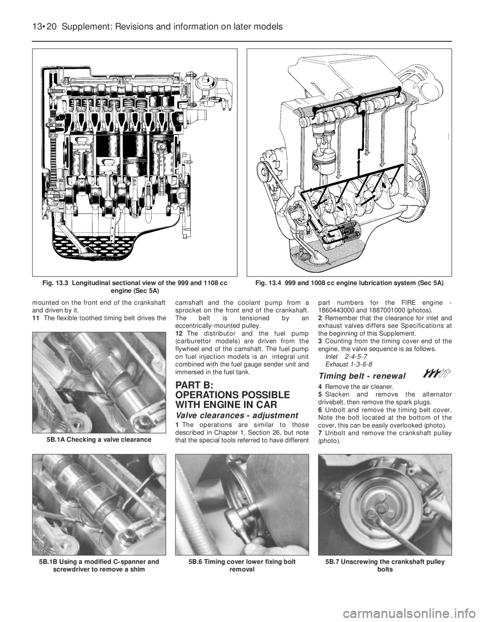
mounted on the front end of the crankshaft
and driven by it.
11The flexible toothed timing belt drives thecamshaft and the coolant pump from a
sprocket on the front end of the crankshaft.
The belt is tensioned by an
eccentrically-mounted pulley.
12The distributor and the fuel pump
(carburettor models) are driven from the
flywheel end of the camshaft. The fuel pump
on fuel injection models is an integral unit
combined with the fuel gauge sender unit and
immersed in the fuel tank.
PART B:
OPERATIONS POSSIBLE
WITH ENGINE IN CAR
Valve clearances - adjustment
1The operations are similar to those
described in Chapter 1, Section 26, but note
that the special tools referred to have differentpart numbers for the FlRE engine -
1860443000 and 1887001000 (photos).
2Remember that the clearance for inlet and
exhaust valves differs see Specifications at
the beginning of this Supplement.
3Counting from the timing cover end of the
engine, the valve sequence is as follows.
Inlet 2-4-5-7
Exhaust 1-3-6-8
Timing belt - renewal #
4Remove the air cleaner.
5Slacken and remove the alternator
drivebelt, then remove the spark plugs.
6Unbolt and remove the timing belt cover.
Note the bolt located at the bottom of the
cover, this can be easily overlooked (photo).
7Unbolt and remove the crankshaft pulley
(photo).
13•20 Supplement: Revisions and information on later models
5B.7 Unscrewing the crankshaft pulley
bolts5B.6 Timing cover lower fixing bolt
removal5B.1B Using a modified C-spanner and
screwdriver to remove a shim
5B.1A Checking a valve clearance
Fig. 13.3 Longitudinal sectional view of the 999 and 1108 cc
engine (Sec 5A)Fig. 13.4 999 and 1008 cc engine lubrication system (Sec 5A)
Page 146 of 303
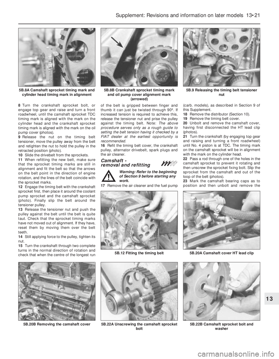
8Turn the crankshaft sprocket bolt, or
engage top gear and raise and turn a front
roadwheel, until the camshaft sprocket TDC
timing mark is aligned with the mark on the
cylinder head and the crankshaft sprocket
timing mark is aligned with the mark on the oil
pump cover (photos).
9Release the nut on the timing belt
tensioner, move the pulley away from the belt
and retighten the nut to hold the pulley in the
retracted position (photo).
10Slide the drivebelt from the sprockets.
11When refitting the new belt, make sure
that the sprocket timing marks are still in
alignment and fit the belt so that the arrows
on the belt point in the direction of engine
rotation, and the lines of the belt coincide with
the sprocket marks.
12Engage the timing belt with the crankshaft
sprocket first, then place it around the coolant
pump sprocket and the camshaft sprocket
(photo). Finally slip the belt around the
tensioner pulley.
13Release the tensioner nut and push the
pulley against the belt until the belt is quite
taut. Check that the sprocket timing marks
have not moved out of alignment. If they have,
reset them by moving them over the belt
teeth.
14Still applying force to the pulley, tighten its
nut.
15Turn the crankshaft through two complete
turns in the normal direction of rotation and
check that when the centre of the longest runof the belt is gripped between finger and
thumb it can just be twisted through 90º. If
increased tension is required to achieve this,
release the tensioner nut and prise the pulley
against the timing belt. Note: The above
procedure serves only as a rough guide to
setting the belt tension having it checked by a
FIAT dealer at the earliest opportunity is
recommended.
16Refit the timing belt cover, the crankshaft
pulley, alternator drivebelt, spark plugs and
the air cleaner.
Camshaft -
removal and refitting#
Warning: Refer to the beginning
of Section 9 before starting any
work.
17Remove the air cleaner and the fuel pump(carb. models), as described in Section 9 of
this Supplement.
18Remove the distributor (Section 10).
19Remove the timing belt cover.
20Unbolt and remove the camshaft cover,
having first disconnected the HT lead clip
(photos).
21Turn the crankshaft (by engaging top gear
and raising and turning a front roadwheel)
until No. 4 piston is at TDC. The timing mark
on the camshaft sprocket will be in alignment
with the mark on the cylinder head.
22Pass a rod through one of the holes in the
camshaft sprocket to prevent it rotating and
then unscrew the sprocket fixing bolt. Slip the
sprocket from the camshaft and out of the
loop of the belt (photos).
23Mark the camshaft bearing caps as to
position and then unbolt and remove the
Supplement: Revisions and information on later models 13•21
5B.9 Releasing the timing belt tensioner
nut5B.8B Crankshaft sprocket timing mark
and oil pump cover alignment mark
(arrowed)5B.8A Camshaft sprocket timing mark and
cylinder head timing mark in alignment
5B.22B Camshaft sprocket bolt and
washer5B.22A Unscrewing the camshaft sprocket
bolt
5B.20A Camshaft cover HT lead clip5B.12 Fitting the timing belt
5B.20B Removing the camshaft cover
13
Page 147 of 303
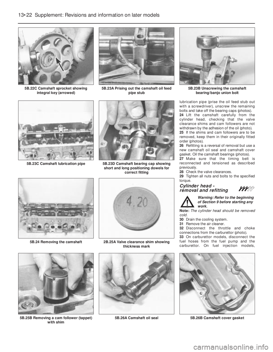
lubrication pipe (prise the oil feed stub out
with a screwdriver), unscrew the remaining
bolts and take off the bearing caps (photos).
24Lift the camshaft carefully from the
cylinder head, checking that the valve
clearance shims and cam followers are not
withdrawn by the adhesion of the oil (photo).
25If the shims and cam followers are to be
removed, keep them in their originally fitted
order (photos).
26Refitting is a reversal of removal but use a
new camshaft oil seal and camshaft cover
gasket. Oil the camshaft bearings (photos).
27Make sure that the timing belt is
reconnected and tensioned as described
previously.
28Check the valve clearances.
29Tighten all nuts and bolts to the specified
torque.
Cylinder head -
removal and refitting#
Warning: Refer to the beginning
of Section 9 before starting any
work.
Note: The cylinder head should be removed
cold.
30Drain the cooling system.
31Remove the air cleaner.
32Disconnect the throttle and choke
connections from the carburettor (photo).
33On carburettor models, disconnect the
fuel hoses from the fuel pump and the
carburettor. On fuel injection models,
13•22 Supplement: Revisions and information on later models
5B.26B Camshaft cover gasket5B.26A Camshaft oil seal5B.25B Removing a cam follower (tappet)
with shim
2B.25A Valve clearance shim showing
thickness mark5B.24 Removing the camshaft
5B.23D Camshaft bearing cap showing
short and long positioning dowels for
correct fitting5B.23C Camshaft lubrication pipe
5B.23B Unscrewing the camshaft
bearing/banjo union bolt5B.23A Prising out the camshaft oil feed
pipe stub5B.22C Camshaft sprocket showing
integral key (arrowed)
Page 148 of 303
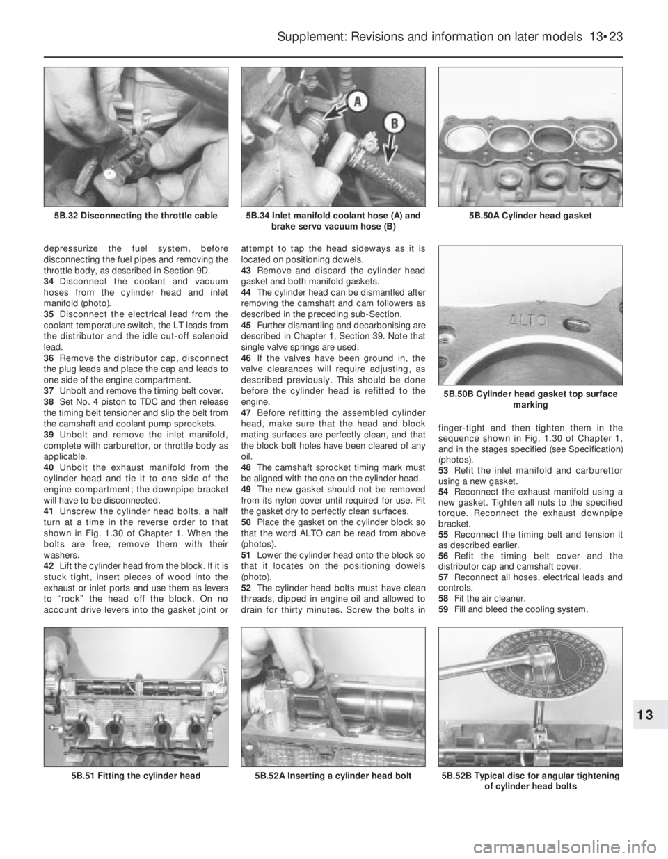
depressurize the fuel system, before
disconnecting the fuel pipes and removing the
throttle body, as described in Section 9D.
34Disconnect the coolant and vacuum
hoses from the cylinder head and inlet
manifold (photo).
35Disconnect the electrical lead from the
coolant temperature switch, the LT leads from
the distributor and the idle cut-off solenoid
lead.
36Remove the distributor cap, disconnect
the plug leads and place the cap and leads to
one side of the engine compartment.
37Unbolt and remove the timing belt cover.
38Set No. 4 piston to TDC and then release
the timing belt tensioner and slip the belt from
the camshaft and coolant pump sprockets.
39Unbolt and remove the inlet manifold,
complete with carburettor, or throttle body as
applicable.
40Unbolt the exhaust manifold from the
cylinder head and tie it to one side of the
engine compartment; the downpipe bracket
will have to be disconnected.
41Unscrew the cylinder head bolts, a half
turn at a time in the reverse order to that
shown in Fig. 1.30 of Chapter 1. When the
bolts are free, remove them with their
washers.
42Lift the cylinder head from the block. If it is
stuck tight, insert pieces of wood into the
exhaust or inlet ports and use them as levers
to “rock” the head off the block. On no
account drive levers into the gasket joint orattempt to tap the head sideways as it is
located on positioning dowels.
43Remove and discard the cylinder head
gasket and both manifold gaskets.
44The cylinder head can be dismantled after
removing the camshaft and cam followers as
described in the preceding sub-Section.
45Further dismantling and decarbonising are
described in Chapter 1, Section 39. Note that
single valve springs are used.
46If the valves have been ground in, the
valve clearances will require adjusting, as
described previously. This should be done
before the cylinder head is refitted to the
engine.
47Before refitting the assembled cylinder
head, make sure that the head and block
mating surfaces are perfectly clean, and that
the block bolt holes have been cleared of any
oil.
48The camshaft sprocket timing mark must
be aligned with the one on the cylinder head.
49The new gasket should not be removed
from its nylon cover until required for use. Fit
the gasket dry to perfectly clean surfaces.
50Place the gasket on the cylinder block so
that the word ALTO can be read from above
(photos).
51Lower the cylinder head onto the block so
that it locates on the positioning dowels
(photo).
52The cylinder head bolts must have clean
threads, dipped in engine oil and allowed to
drain for thirty minutes. Screw the bolts infinger-tight and then tighten them in the
sequence shown in Fig. 1.30 of Chapter 1,
and in the stages specified (see Specification)
(photos).
53Refit the inlet manifold and carburettor
using a new gasket.
54Reconnect the exhaust manifold using a
new gasket. Tighten all nuts to the specified
torque. Reconnect the exhaust downpipe
bracket.
55Reconnect the timing belt and tension it
as described earlier.
56Refit the timing belt cover and the
distributor cap and camshaft cover.
57Reconnect all hoses, electrical leads and
controls.
58Fit the air cleaner.
59Fill and bleed the cooling system.
Supplement: Revisions and information on later models 13•23
5B.50A Cylinder head gasket5B.34 Inlet manifold coolant hose (A) and
brake servo vacuum hose (B)5B.32 Disconnecting the throttle cable
5B.52B Typical disc for angular tightening
of cylinder head bolts
5B.50B Cylinder head gasket top surface
marking
5B.52A Inserting a cylinder head bolt5B.51 Fitting the cylinder head
13
Page 149 of 303
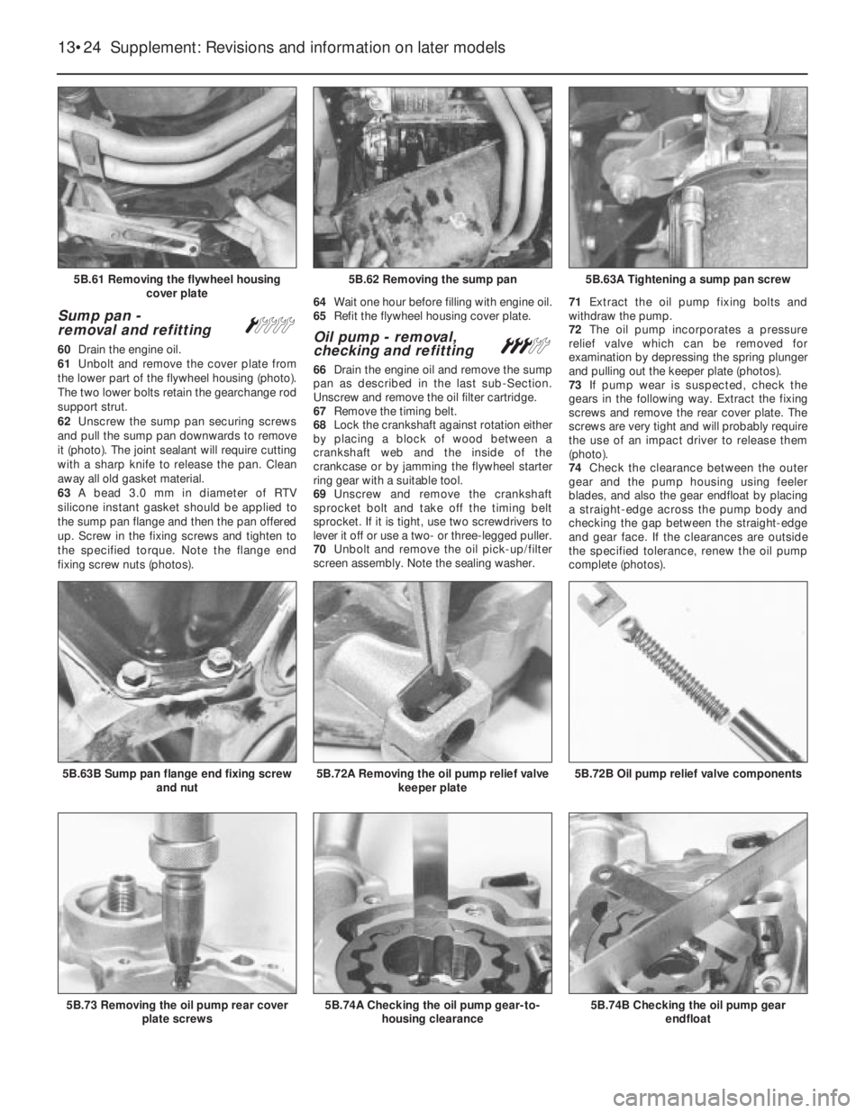
Sump pan -
removal and refitting Á
60Drain the engine oil.
61Unbolt and remove the cover plate from
the lower part of the flywheel housing (photo).
The two lower bolts retain the gearchange rod
support strut.
62Unscrew the sump pan securing screws
and pull the sump pan downwards to remove
it (photo). The joint sealant will require cutting
with a sharp knife to release the pan. Clean
away all old gasket material.
63A bead 3.0 mm in diameter of RTV
silicone instant gasket should be applied to
the sump pan flange and then the pan offered
up. Screw in the fixing screws and tighten to
the specified torque. Note the flange end
fixing screw nuts (photos).64Wait one hour before filling with engine oil.
65Refit the flywheel housing cover plate.Oil pump - removal,
checking and refitting#
66Drain the engine oil and remove the sump
pan as described in the last sub-Section.
Unscrew and remove the oil filter cartridge.
67Remove the timing belt.
68Lock the crankshaft against rotation either
by placing a block of wood between a
crankshaft web and the inside of the
crankcase or by jamming the flywheel starter
ring gear with a suitable tool.
69Unscrew and remove the crankshaft
sprocket bolt and take off the timing belt
sprocket. If it is tight, use two screwdrivers to
lever it off or use a two- or three-legged puller.
70Unbolt and remove the oil pick-up/filter
screen assembly. Note the sealing washer.71Extract the oil pump fixing bolts and
withdraw the pump.
72The oil pump incorporates a pressure
relief valve which can be removed for
examination by depressing the spring plunger
and pulling out the keeper plate (photos).
73If pump wear is suspected, check the
gears in the following way. Extract the fixing
screws and remove the rear cover plate. The
screws are very tight and will probably require
the use of an impact driver to release them
(photo).
74Check the clearance between the outer
gear and the pump housing using feeler
blades, and also the gear endfloat by placing
a straight-edge across the pump body and
checking the gap between the straight-edge
and gear face. If the clearances are outside
the specified tolerance, renew the oil pump
complete (photos).
13•24 Supplement: Revisions and information on later models
5B.74B Checking the oil pump gear
endfloat5B.74A Checking the oil pump gear-to-
housing clearance5B.73 Removing the oil pump rear cover
plate screws
5B.72B Oil pump relief valve components5B.72A Removing the oil pump relief valve
keeper plate5B.63B Sump pan flange end fixing screw
and nut
5B.63A Tightening a sump pan screw5B.62 Removing the sump pan5B.61 Removing the flywheel housing
cover plate