1983 FIAT UNO fuel cap
[x] Cancel search: fuel capPage 146 of 303
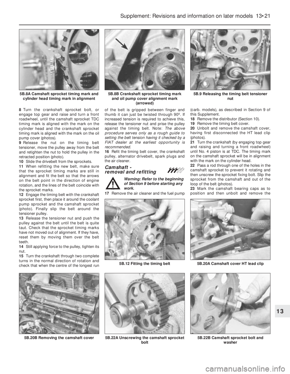
8Turn the crankshaft sprocket bolt, or
engage top gear and raise and turn a front
roadwheel, until the camshaft sprocket TDC
timing mark is aligned with the mark on the
cylinder head and the crankshaft sprocket
timing mark is aligned with the mark on the oil
pump cover (photos).
9Release the nut on the timing belt
tensioner, move the pulley away from the belt
and retighten the nut to hold the pulley in the
retracted position (photo).
10Slide the drivebelt from the sprockets.
11When refitting the new belt, make sure
that the sprocket timing marks are still in
alignment and fit the belt so that the arrows
on the belt point in the direction of engine
rotation, and the lines of the belt coincide with
the sprocket marks.
12Engage the timing belt with the crankshaft
sprocket first, then place it around the coolant
pump sprocket and the camshaft sprocket
(photo). Finally slip the belt around the
tensioner pulley.
13Release the tensioner nut and push the
pulley against the belt until the belt is quite
taut. Check that the sprocket timing marks
have not moved out of alignment. If they have,
reset them by moving them over the belt
teeth.
14Still applying force to the pulley, tighten its
nut.
15Turn the crankshaft through two complete
turns in the normal direction of rotation and
check that when the centre of the longest runof the belt is gripped between finger and
thumb it can just be twisted through 90º. If
increased tension is required to achieve this,
release the tensioner nut and prise the pulley
against the timing belt. Note: The above
procedure serves only as a rough guide to
setting the belt tension having it checked by a
FIAT dealer at the earliest opportunity is
recommended.
16Refit the timing belt cover, the crankshaft
pulley, alternator drivebelt, spark plugs and
the air cleaner.
Camshaft -
removal and refitting#
Warning: Refer to the beginning
of Section 9 before starting any
work.
17Remove the air cleaner and the fuel pump(carb. models), as described in Section 9 of
this Supplement.
18Remove the distributor (Section 10).
19Remove the timing belt cover.
20Unbolt and remove the camshaft cover,
having first disconnected the HT lead clip
(photos).
21Turn the crankshaft (by engaging top gear
and raising and turning a front roadwheel)
until No. 4 piston is at TDC. The timing mark
on the camshaft sprocket will be in alignment
with the mark on the cylinder head.
22Pass a rod through one of the holes in the
camshaft sprocket to prevent it rotating and
then unscrew the sprocket fixing bolt. Slip the
sprocket from the camshaft and out of the
loop of the belt (photos).
23Mark the camshaft bearing caps as to
position and then unbolt and remove the
Supplement: Revisions and information on later models 13•21
5B.9 Releasing the timing belt tensioner
nut5B.8B Crankshaft sprocket timing mark
and oil pump cover alignment mark
(arrowed)5B.8A Camshaft sprocket timing mark and
cylinder head timing mark in alignment
5B.22B Camshaft sprocket bolt and
washer5B.22A Unscrewing the camshaft sprocket
bolt
5B.20A Camshaft cover HT lead clip5B.12 Fitting the timing belt
5B.20B Removing the camshaft cover
13
Page 147 of 303
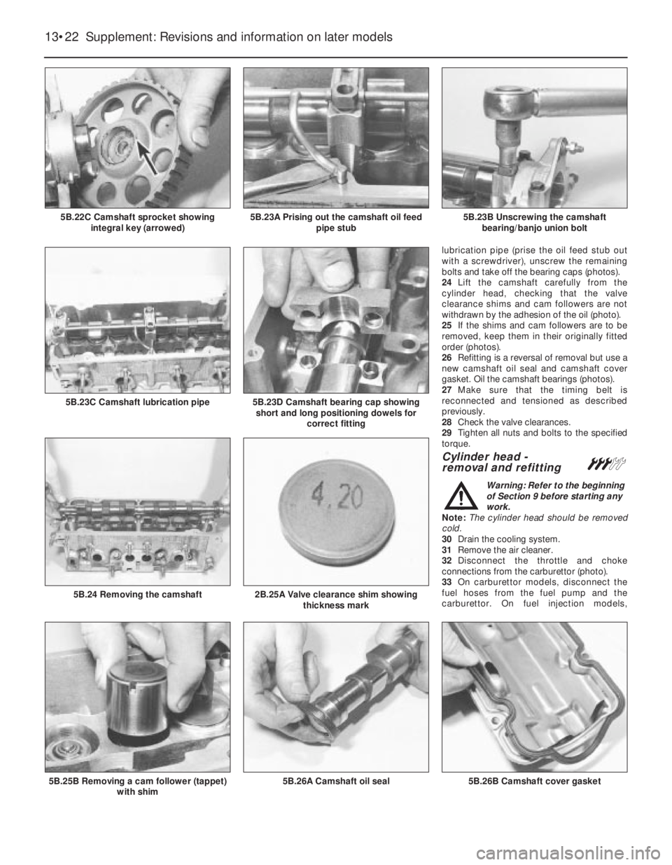
lubrication pipe (prise the oil feed stub out
with a screwdriver), unscrew the remaining
bolts and take off the bearing caps (photos).
24Lift the camshaft carefully from the
cylinder head, checking that the valve
clearance shims and cam followers are not
withdrawn by the adhesion of the oil (photo).
25If the shims and cam followers are to be
removed, keep them in their originally fitted
order (photos).
26Refitting is a reversal of removal but use a
new camshaft oil seal and camshaft cover
gasket. Oil the camshaft bearings (photos).
27Make sure that the timing belt is
reconnected and tensioned as described
previously.
28Check the valve clearances.
29Tighten all nuts and bolts to the specified
torque.
Cylinder head -
removal and refitting#
Warning: Refer to the beginning
of Section 9 before starting any
work.
Note: The cylinder head should be removed
cold.
30Drain the cooling system.
31Remove the air cleaner.
32Disconnect the throttle and choke
connections from the carburettor (photo).
33On carburettor models, disconnect the
fuel hoses from the fuel pump and the
carburettor. On fuel injection models,
13•22 Supplement: Revisions and information on later models
5B.26B Camshaft cover gasket5B.26A Camshaft oil seal5B.25B Removing a cam follower (tappet)
with shim
2B.25A Valve clearance shim showing
thickness mark5B.24 Removing the camshaft
5B.23D Camshaft bearing cap showing
short and long positioning dowels for
correct fitting5B.23C Camshaft lubrication pipe
5B.23B Unscrewing the camshaft
bearing/banjo union bolt5B.23A Prising out the camshaft oil feed
pipe stub5B.22C Camshaft sprocket showing
integral key (arrowed)
Page 148 of 303
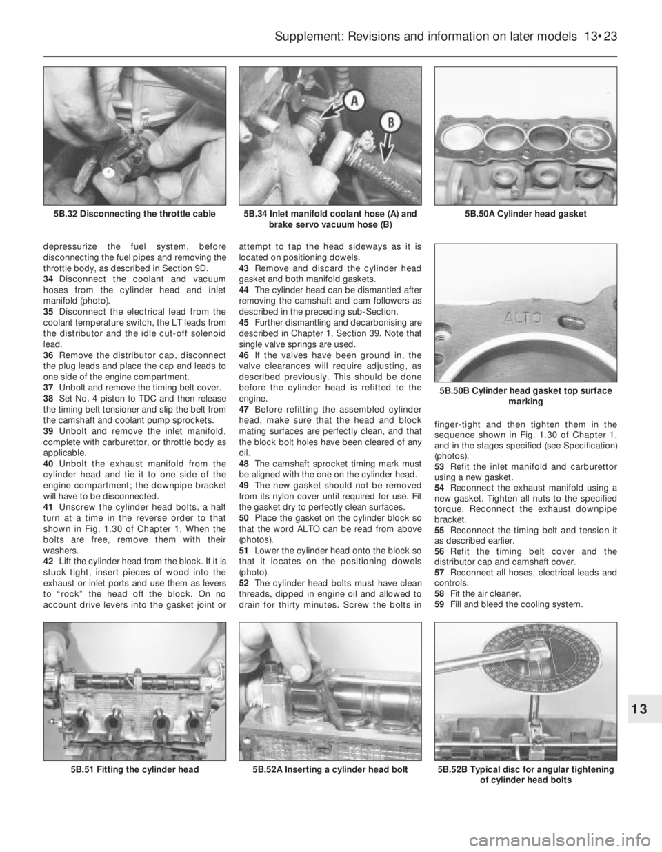
depressurize the fuel system, before
disconnecting the fuel pipes and removing the
throttle body, as described in Section 9D.
34Disconnect the coolant and vacuum
hoses from the cylinder head and inlet
manifold (photo).
35Disconnect the electrical lead from the
coolant temperature switch, the LT leads from
the distributor and the idle cut-off solenoid
lead.
36Remove the distributor cap, disconnect
the plug leads and place the cap and leads to
one side of the engine compartment.
37Unbolt and remove the timing belt cover.
38Set No. 4 piston to TDC and then release
the timing belt tensioner and slip the belt from
the camshaft and coolant pump sprockets.
39Unbolt and remove the inlet manifold,
complete with carburettor, or throttle body as
applicable.
40Unbolt the exhaust manifold from the
cylinder head and tie it to one side of the
engine compartment; the downpipe bracket
will have to be disconnected.
41Unscrew the cylinder head bolts, a half
turn at a time in the reverse order to that
shown in Fig. 1.30 of Chapter 1. When the
bolts are free, remove them with their
washers.
42Lift the cylinder head from the block. If it is
stuck tight, insert pieces of wood into the
exhaust or inlet ports and use them as levers
to “rock” the head off the block. On no
account drive levers into the gasket joint orattempt to tap the head sideways as it is
located on positioning dowels.
43Remove and discard the cylinder head
gasket and both manifold gaskets.
44The cylinder head can be dismantled after
removing the camshaft and cam followers as
described in the preceding sub-Section.
45Further dismantling and decarbonising are
described in Chapter 1, Section 39. Note that
single valve springs are used.
46If the valves have been ground in, the
valve clearances will require adjusting, as
described previously. This should be done
before the cylinder head is refitted to the
engine.
47Before refitting the assembled cylinder
head, make sure that the head and block
mating surfaces are perfectly clean, and that
the block bolt holes have been cleared of any
oil.
48The camshaft sprocket timing mark must
be aligned with the one on the cylinder head.
49The new gasket should not be removed
from its nylon cover until required for use. Fit
the gasket dry to perfectly clean surfaces.
50Place the gasket on the cylinder block so
that the word ALTO can be read from above
(photos).
51Lower the cylinder head onto the block so
that it locates on the positioning dowels
(photo).
52The cylinder head bolts must have clean
threads, dipped in engine oil and allowed to
drain for thirty minutes. Screw the bolts infinger-tight and then tighten them in the
sequence shown in Fig. 1.30 of Chapter 1,
and in the stages specified (see Specification)
(photos).
53Refit the inlet manifold and carburettor
using a new gasket.
54Reconnect the exhaust manifold using a
new gasket. Tighten all nuts to the specified
torque. Reconnect the exhaust downpipe
bracket.
55Reconnect the timing belt and tension it
as described earlier.
56Refit the timing belt cover and the
distributor cap and camshaft cover.
57Reconnect all hoses, electrical leads and
controls.
58Fit the air cleaner.
59Fill and bleed the cooling system.
Supplement: Revisions and information on later models 13•23
5B.50A Cylinder head gasket5B.34 Inlet manifold coolant hose (A) and
brake servo vacuum hose (B)5B.32 Disconnecting the throttle cable
5B.52B Typical disc for angular tightening
of cylinder head bolts
5B.50B Cylinder head gasket top surface
marking
5B.52A Inserting a cylinder head bolt5B.51 Fitting the cylinder head
13
Page 154 of 303
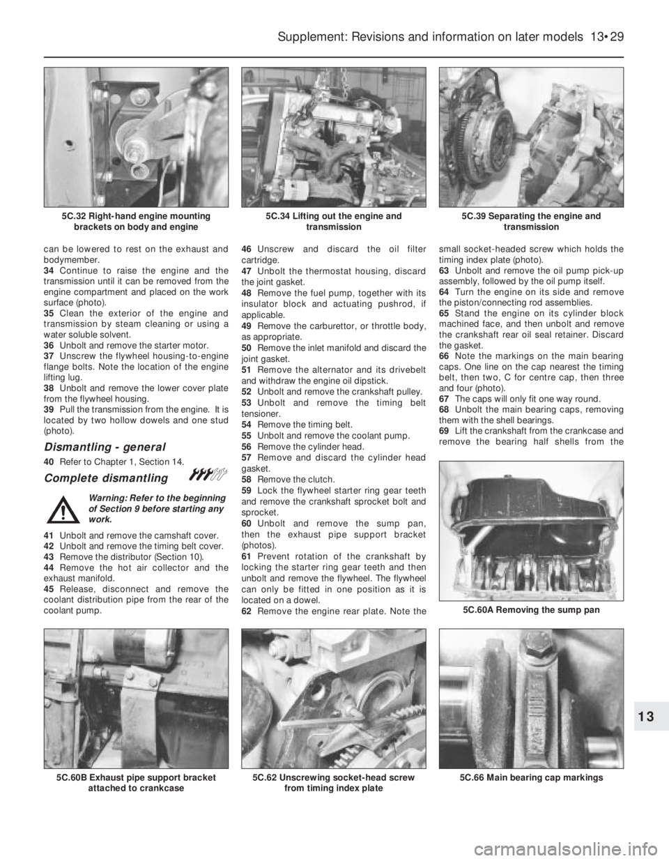
can be lowered to rest on the exhaust and
bodymember.
34Continue to raise the engine and the
transmission until it can be removed from the
engine compartment and placed on the work
surface (photo).
35Clean the exterior of the engine and
transmission by steam cleaning or using a
water soluble solvent.
36Unbolt and remove the starter motor.
37Unscrew the flywheel housing-to-engine
flange bolts. Note the location of the engine
lifting lug.
38Unbolt and remove the lower cover plate
from the flywheel housing.
39Pull the transmission from the engine. It is
located by two hollow dowels and one stud
(photo).
Dismantling - general
40Refer to Chapter 1, Section 14.
Complete dismantling#
Warning: Refer to the beginning
of Section 9 before starting any
work.
41Unbolt and remove the camshaft cover.
42Unbolt and remove the timing belt cover.
43Remove the distributor (Section 10).
44Remove the hot air collector and the
exhaust manifold.
45Release, disconnect and remove the
coolant distribution pipe from the rear of the
coolant pump.46Unscrew and discard the oil filter
cartridge.
47Unbolt the thermostat housing, discard
the joint gasket.
48Remove the fuel pump, together with its
insulator block and actuating pushrod, if
applicable.
49Remove the carburettor, or throttle body,
as appropriate.
50Remove the inlet manifold and discard the
joint gasket.
51Remove the alternator and its drivebelt
and withdraw the engine oil dipstick.
52Unbolt and remove the crankshaft pulley.
53Unbolt and remove the timing belt
tensioner.
54Remove the timing belt.
55Unbolt and remove the coolant pump.
56Remove the cylinder head.
57Remove and discard the cylinder head
gasket.
58Remove the clutch.
59Lock the flywheel starter ring gear teeth
and remove the crankshaft sprocket bolt and
sprocket.
60Unbolt and remove the sump pan,
then the exhaust pipe support bracket
(photos).
61Prevent rotation of the crankshaft by
locking the starter ring gear teeth and then
unbolt and remove the flywheel. The flywheel
can only be fitted in one position as it is
located on a dowel.
62Remove the engine rear plate. Note thesmall socket-headed screw which holds the
timing index plate (photo).
63Unbolt and remove the oil pump pick-up
assembly, followed by the oil pump itself.
64Turn the engine on its side and remove
the piston/connecting rod assemblies.
65Stand the engine on its cylinder block
machined face, and then unbolt and remove
the crankshaft rear oil seal retainer. Discard
the gasket.
66Note the markings on the main bearing
caps. One line on the cap nearest the timing
belt, then two, C for centre cap, then three
and four (photo).
67The caps will only fit one way round.
68Unbolt the main bearing caps, removing
them with the shell bearings.
69Lift the crankshaft from the crankcase and
remove the bearing half shells from the
Supplement: Revisions and information on later models 13•29
5C.39 Separating the engine and
transmission5C.34 Lifting out the engine and
transmission5C.32 Right-hand engine mounting
brackets on body and engine
5C.66 Main bearing cap markings
5C.60A Removing the sump pan
5C.62 Unscrewing socket-head screw
from timing index plate5C.60B Exhaust pipe support bracket
attached to crankcase
13
Page 168 of 303

98Commence reassembly by liberally oiling
the bearings in the housing, and the oil seal lip.
99Carefully insert the camshaft into the
housing from the blanking plate/distributor
end, taking care to avoid damage to the
bearings.
100Refit the blanking plate using a new
gasket.
101Refit the camshaft housing as described
previously in this Section.
Cylinder head
(1372 cc ie engine) -
removal and refitting
#
Note: The following instructions describe
cylinder head removal and refitting leaving the
camshaft, manifolds and associated items in situ
In the head. If required, these items can be
removed separately. When removing the
cylinder head the engine must be cold - do not
remove the head from a hot engine. A new
cylinder head gasket and any associated gaskets
must be used during reassembly. FIAT specify
that the main cylinder head bolts should be
renewed after they have been used (ie tightened)
four times. If in any doubt as to the number of
times that they have been used renew them as a
precaution against possible failure.
Warning: Refer to the beginning
of Section 9 before starting any
work.
102Depressurise the fuel supply system as
described in Section 9 of this Chapter.
103Disconnect the battery negative lead.
104Drain the engine coolant as described in
Section 8.
105Remove the air cleaner unit as described
in Section 9.
106Remove the timing belt as described
previously in this Section.107Disconnect the crankcase ventilation
hose from the cylinder head and the SPi
injector unit.
108Disconnect the accelerator cable at the
engine end.
109Detach the engine idle speed check
actuator lead, the inlet manifold vacuum
sensor lead, the coolant temperature sensor
lead, the injector supply lead, the throttle
position switch lead and the distributor cap
(with HT leads). Position them out of the way.
110Disconnect the brake servo hose from
the manifold.
111Disconnect the coolant hoses from the
thermostat and the inlet manifold.
112Slowly release the fuel supply and return
hose retaining clips and detach the hoses
from the injector unit housing and
connections. Catch any fuel spillage in a clean
cloth and plug the hoses to prevent the
ingress of dirt and further fuel loss.
113Unbolt and detach the exhaust downpipe
from the manifold.
114Loosen off the cylinder head retaining
bolts in a progressive manner, reversing the
sequence shown in Fig. 13.17. When all of the
bolts are loosened off, extract them and
collect the washers.
115Check that all fittings and associated
attachments are clear of the cylinder head,
then carefully lift the head from the cylinder
block. If necessary tap the head lightly with a
soft-faced mallet to free it from the block, but
do not lever it free between the joint faces.
Note that the cylinder head is located on
dowels.116Recover the old cylinder head gasket and
discard it.
117Clean the cylinder head and block mating
surfaces by careful scraping. Take care not to
damage the cylinder head - it is manufactured in
light alloy and is easily scored. Cover the coolant
passages and other openings to prevent dirt and
carbon from falling into them. Mop out all the oil
from the cylinder head bolt holes - if oil is left in
them, hydraulic pressure, caused when the bolts
are refitted, could cause the block to crack.
118If required the cylinder head can be
dismantled and overhauled as described in
paragraphs 129 to 131 of this Section.
119The new gasket must be removed from
its protective packing just before it is fitted.
Do not allow any oil or grease to come into
contact with the gasket. Commence refitting
the cylinder head by locating the new gasket
on the cylinder block so that the word “ALTO”
is facing up (photo).
120With the mating faces scrupulously
clean, refit the cylinder head into position and
engage it over the dowels. Refer to the note at
the beginning of this part of the Section, then
refit the ten main cylinder head bolts and
washers. Screw each bolt in as far as possible
by hand to start with. Do not fit the smaller
(M8 x 1.25) bolts at this stage (photos).
121The bolts must now be tightened in stages
and in the sequence shown in Fig. 13.17. Refer
to the specified torque wrench settings and
tighten all bolts to the Stage 1 torque, then
using a suitable angle gauge, tighten them to
the second stage, then the third stage (photos).
122With the main cylinder head bolts fully
Supplement: Revisions and information on later models 13•43
7B.120B . . . and engage the positioning
dowels in their holes7B.120A Lower the cylinder head onto the
block . . .7B.119 Locating a new cylinder head
gasket on the cylinder block (engine
shown on dismantling stand)
7B.121A Tighten main cylinder head bolts
to specified torque . . .Fig. 13.17 Cylinder head bolt tightening
sequence on the 1372 cc ie and Turbo ie
engines (Sec 7B)
13
7B.121B . . . and then through the specified
angle
Page 174 of 303

fitting, as during removal. Note that the
compression rings are brittle, and will snap if
expanded too far.
206If new pistons are to be fitted, they must
be selected from the grades available, after
measuring the cylinder bores. Normally, the
appropriate oversize pistons are supplied by
the dealer when the block is rebored.
207Whenever new piston rings are being
installed, the glaze on the original cylinder
bores should be removed using either
abrasive paper or a glaze-removing tool in an
electric drill. If abrasive paper is used, use
strokes at 60º to the bore centre-line, to
create a cross-hatching effect.
Engine/transmission
mountings - renewalÁ
208The engine/gearbox assembly is
suspended in the engine compartment on
three mountings, two of which are attached to
the gearbox, and one to the engine.
Right-hand mounting
209Apply the handbrake, then jack up the
front of the vehicle and support it securely on
axle stands.
210Suitable lifting tackle must now be
attached to the engine in order to support it as
the engine mounting is removed. No lifting
brackets are provided, so care must be taken
when deciding on an engine lifting point. In the
workshop, a right-angled bracket was made up
by bending a suitable piece of steel plate. The
bracket was then bolted to the engine using the
rear right-hand camshaft housing securing bolt
with suitable packing washers.
211Attach the lifting tackle to the bracket on
the engine and just take the weight of the
assembly.
212Working under the vehicle, unbolt the
engine mounting bracket from the cylinder
block, and unbolt the mounting from the
body, then withdraw the bracket/mounting
assembly.
213Unscrew the nut and through-bolt,
counter holding the bolt with a second
spanner or socket, and separate the mounting
from the bracket.
214Fit the new mounting to the bracket, and
tighten the nut to the specified torque, while
counterholding the through-bolt using a
suitable spanner or socket.
215Refit the mounting bracket to the cylinder
block, and tighten the securing bolts to the
specified torque.
216Refit the mounting to the body and
tighten the securing bolts to the specified
torque.
217Disconnect the lifting tackle from the
engine, and remove the engine lifting bracket.
218Lower the vehicle to the ground.
Left-hand mountings
219Apply the handbrake, then jack up the
front of the vehicle and support it securely on
axle stands.
220Suitable lifting tackle must now be
attached to the gearbox lifting bracket inorder to support the weight of the assembly
as the mounting is removed.
221Attach the lifting tackle to the bracket on
the gearbox, and just take the weight of the
assembly.
222Working under the vehicle, unbolt the
mounting bracket from the gearbox, and
unbolt the mounting from the body, then
withdraw the bracket/mounting assembly.
223Proceed as described in paragraphs 213
and 214.
224Refit the mounting bracket to the
gearbox, and tighten the securing bolts to the
specified torque.
225Refit the mounting to the body and
tighten the mounting bolts to the specified
torque.
226Disconnect the lifting tackle from the
engine.
227Lower the vehicle to the ground.
PART C: ENGINE REMOVAL
AND DISMANTLING
Method of removal - general
1The engine (complete with transmission) is
disconnected and lowered downwards
through the engine compartment, then
withdrawn from the front underside of the car.
1372 cc engine/
transmission - removal
and separation
#
Warning: Refer to the beginning
of Section 9 before starting any
work.
2Depressurize the fuel system as described
in Section 9 of this Chapter.
3Disconnect the battery negative lead.
4Mark the position of the hinges on the
underside of the bonnet, then with the aid of
an assistant, unscrew the hinge bolts and lift
the bonnet clear of the car. Store the bonnet
in a safe area.
5Drain the engine coolant.
6Drain the engine and transmission oils.
7Disconnect and remove the air filter.
8Disconnect the coolant hoses from the
engine, including the hose to the inlet
manifold.
9Detach the ignition coil (HT) lead from the
distributor.10Compress the retaining clip and detach
the engine idle speed actuator lead from the
SPi unit (photo).
11Disconnect the brake servo vacuum pipe
from its connector on the inlet manifold.
12Disconnect the throttle cable from the SPi
unit.
13Disconnect the engine speed sensor lead.
14Release and detach the reversing light
lead from the switch on the transmission
(photo).
15Before disconnecting the hydraulic hose
from the clutch slave cylinder, remove the
filler cap from the reservoir and place a piece
of polythene sheet over the filler neck, then
refit the cap; this will help prevent excess fluid
loss. Once disconnected, plug the hose and
its cylinder connection to prevent the ingress
of dirt into the hydraulic system.
16Disconnect the wiring connector from the
alternator.
17Position a clean rag under the fuel supply
and return hose connections to the SPi unit,
then slowly unscrew the hose clips to release
the system pressure; catch fuel leakage in the
rag and dispose of it safely. Detach the hoses
and plug them to prevent ingress of dirt and
any further fuel leakage. Position the hoses
out of the way.
18Detach the wiring connector from the
engine coolant temperature sender unit
(photo).
19Release the retaining clip and detach the
wiring connector from the throttle position
switch. Also detach the associated earth
leads from the cylinder head.
Supplement: Revisions and information on later models 13•49
7C.14 Reversing light switch and lead7C.18 Engine coolant temperature sender
and wiring connector
7C.10 Engine idle speed actuator/SPi unit
lead connection (arrowed)
13
Page 179 of 303
removal are in place under the
engine-to-gearbox bolts. Do not allow the
weight of the gearbox to hang on the input
shaft as it is engaged with the clutch friction
disc.
29Refit the starter motor, ensuring that the
wiring harness bracket is in position on the
top bolt.
30Locate the engine/transmission unit at the
front of the car and move it into position under
the engine compartment. Attach the lifting
sling and hoist as during removal.
31Enlist the aid of an assistant to help
steady the combined units as they are raised
into position and to locate the mountings in
the engine compartment.
32Once they are located, tighten the
mountings to the specified torque settings,
then disconnect the lifting hoist and sling.
33The remainder of the refitting and
reconnection procedures are a reversal of the
removal procedure described in Part C. For
further details on reconnecting the
suspension and driveshaft components,
refer to Chapter 7 and Section 13 of this
Chapter.
34Ensure that the exhaust downpipe-to-
manifold connection is clean and renew the
gasket when reconnecting this joint. Use a
smear of exhaust assembly paste on the jointfaces. Use new lockwashers and tighten the
flange nuts securely.
35Ensure that all fuel and coolant
connections are cleanly and securely made.
36Ensure that all wiring connections are
correct and securely made.
37Top up the engine and transmission oil
levels.
38Refill the cooling system.
39Check that all connections are securely
made, then reconnect the battery negative
lead.
Initial start-up after major
overhaul
40Refer to Chapter 1, Section 45.
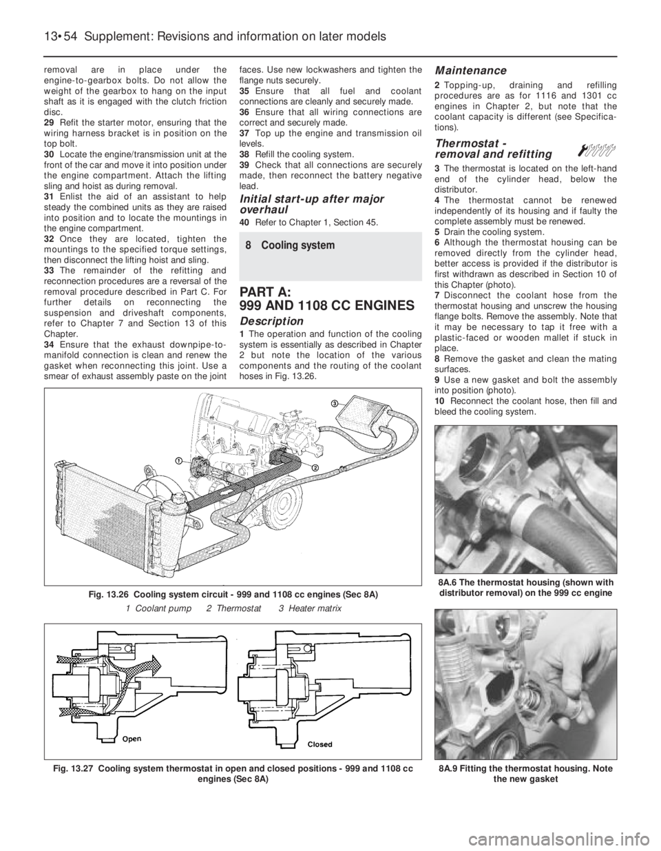
8 Cooling system
PART A:
999 AND 1108 CC ENGINES
Description
1The operation and function of the cooling
system is essentially as described in Chapter
2 but note the location of the various
components and the routing of the coolant
hoses in Fig. 13.26.
Maintenance
2Topping-up, draining and refilling
procedures are as for 1116 and 1301 cc
engines in Chapter 2, but note that the
coolant capacity is different (see Specifica-
tions).
Thermostat -
removal and refittingÁ
3The thermostat is located on the left-hand
end of the cylinder head, below the
distributor.
4The thermostat cannot be renewed
independently of its housing and if faulty the
complete assembly must be renewed.
5Drain the cooling system.
6Although the thermostat housing can be
removed directly from the cylinder head,
better access is provided if the distributor is
first withdrawn as described in Section 10 of
this Chapter (photo).
7Disconnect the coolant hose from the
thermostat housing and unscrew the housing
flange bolts. Remove the assembly. Note that
it may be necessary to tap it free with a
plastic-faced or wooden mallet if stuck in
place.
8Remove the gasket and clean the mating
surfaces.
9Use a new gasket and bolt the assembly
into position (photo).
10Reconnect the coolant hose, then fill and
bleed the cooling system.
13•54 Supplement: Revisions and information on later models
Fig. 13.26 Cooling system circuit - 999 and 1108 cc engines (Sec 8A)
1 Coolant pump 2 Thermostat 3 Heater matrix
Fig. 13.27 Cooling system thermostat in open and closed positions - 999 and 1108 cc
engines (Sec 8A)8A.9 Fitting the thermostat housing. Note
the new gasket
8A.6 The thermostat housing (shown with
distributor removal) on the 999 cc engine
Page 187 of 303
PART B:
CARBURETTOR MODELS
Carburettor (Weber 32 TLF) -
description
Warning: Refer to the beginning
of this Section before starting
any work.
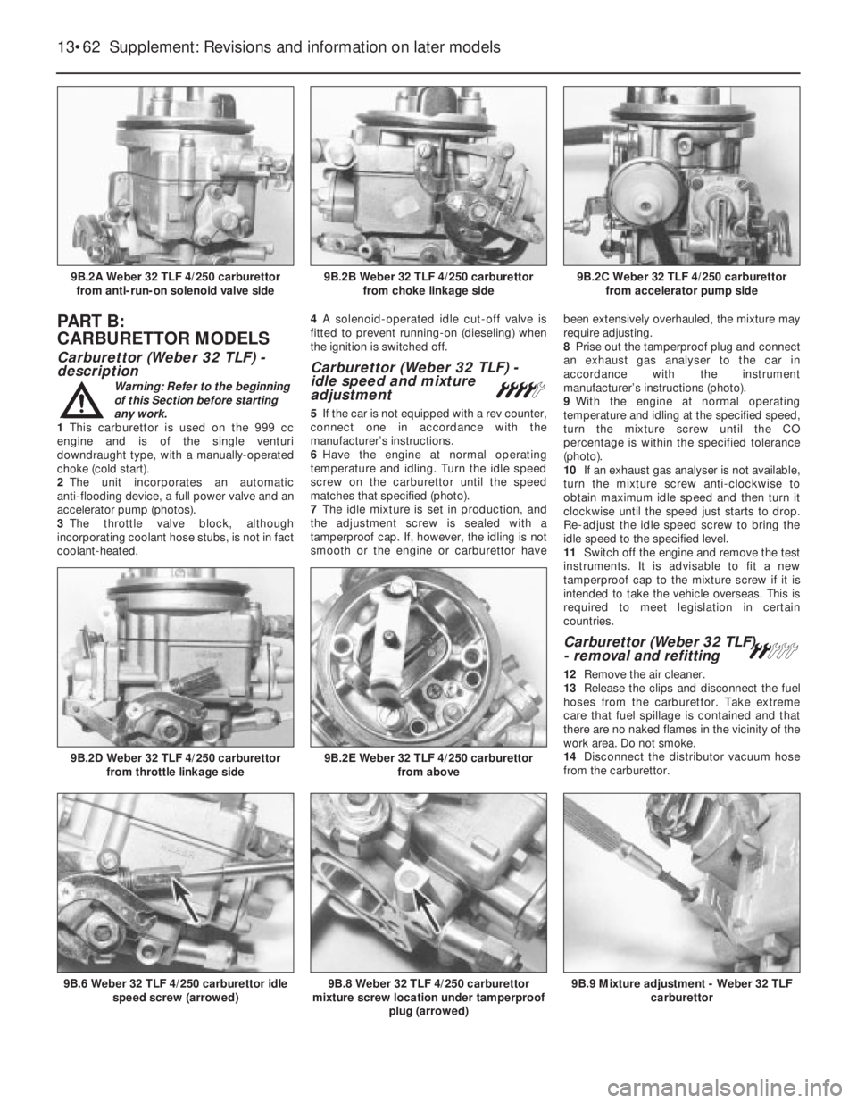
1This carburettor is used on the 999 cc
engine and is of the single venturi
downdraught type, with a manually-operated
choke (cold start).
2The unit incorporates an automatic
anti-flooding device, a full power valve and an
accelerator pump (photos).
3The throttle valve block, although
incorporating coolant hose stubs, is not in fact
coolant-heated.4A solenoid-operated idle cut-off valve is
fitted to prevent running-on (dieseling) when
the ignition is switched off.
Carburettor (Weber 32 TLF) -
idle speed and mixture
adjustment
¢
5If the car is not equipped with a rev counter,
connect one in accordance with the
manufacturer’s instructions.
6Have the engine at normal operating
temperature and idling. Turn the idle speed
screw on the carburettor until the speed
matches that specified (photo).
7The idle mixture is set in production, and
the adjustment screw is sealed with a
tamperproof cap. If, however, the idling is not
smooth or the engine or carburettor havebeen extensively overhauled, the mixture may
require adjusting.
8Prise out the tamperproof plug and connect
an exhaust gas analyser to the car in
accordance with the instrument
manufacturer’s instructions (photo).
9With the engine at normal operating
temperature and idling at the specified speed,
turn the mixture screw until the CO
percentage is within the specified tolerance
(photo).
10If an exhaust gas analyser is not available,
turn the mixture screw anti-clockwise to
obtain maximum idle speed and then turn it
clockwise until the speed just starts to drop.
Re-adjust the idle speed screw to bring the
idle speed to the specified level.
11Switch off the engine and remove the test
instruments. It is advisable to fit a new
tamperproof cap to the mixture screw if it is
intended to take the vehicle overseas. This is
required to meet legislation in certain
countries.
Carburettor (Weber 32 TLF)
- removal and refitting ª
12Remove the air cleaner.
13Release the clips and disconnect the fuel
hoses from the carburettor. Take extreme
care that fuel spillage is contained and that
there are no naked flames in the vicinity of the
work area. Do not smoke.
14Disconnect the distributor vacuum hose
from the carburettor.
13•62 Supplement: Revisions and information on later models
9B.9 Mixture adjustment - Weber 32 TLF
carburettor9B.8 Weber 32 TLF 4/250 carburettor
mixture screw location under tamperproof
plug (arrowed)9B.6 Weber 32 TLF 4/250 carburettor idle
speed screw (arrowed)
9B.2E Weber 32 TLF 4/250 carburettor
from above9B.2D Weber 32 TLF 4/250 carburettor
from throttle linkage side
9B.2C Weber 32 TLF 4/250 carburettor
from accelerator pump side9B.2B Weber 32 TLF 4/250 carburettor
from choke linkage side9B.2A Weber 32 TLF 4/250 carburettor
from anti-run-on solenoid valve side