1983 FIAT UNO fuel type
[x] Cancel search: fuel typePage 144 of 303

4 Engine-
903 and 1299/1301 cc
Sump pan sealing strips (903 cc
engine) - modification
1The design of the sealing strips which go
between the sump pan and the main bearing
caps has been changed. Make sure that the
narrower side of the strip fits into the channel
in the sump pan.
1299 cc engine - description
2In April 1984, a 1299 cc engine was
introduced, progressively replacing the
1301 cc units used previously. The new
engine is identical to the 1301 cc engine
described in Chapter 1, with the exception of
having a slightly shorter stroke.
3However, as of approximately September
1987, the 1299 cc unit was phased out, being
progressively replaced by the 1301 cc engine
used initially.
4As mentioned above, the two engines are
all but identical, so identification of the unit
fitted should not be necessary in practice.
Consult a FIAT dealer if in doubt.
Rocker cover (903 cc engine) -
removal
5Before removing the rocker cover, it will be
necessary to remove the distributor, first.
Refer to Chapter 4 for more details.
Cylinder head (903 cc engine) -
refitting
6Modified cylinder head bolts are fitted to
903 cc models, from engine number 8581470.
When refitting the cylinder head, tighten each
head bolt, as described in Chapter 1, by the
torques and angles shown the Specifications
in this Chapter.
5 Engine-
999 and 1108 cc (FIRE)
Note:Later models are fitted with SPi fuel
injection. Where a procedure refers to a
carburettor, if applicable, replace with throttle
body.
PART A: GENERAL
Description
1Both of these engine types are designated
FIRE (Fully Integrated Robotised Engine),
being largely manufactured and assembled by
computer-controlled mechanical robots.
2The engine is of oversquare design, having
four cylinders and a belt-driven overhead
camshaft.
3The high torque of this engine enableshigher gear ratios to be used with the result
that fuel economy is exceptionally good.
4The cylinder head is of light alloy, while the
cylinder block is cast-iron.
5The camshaft is supported in three
bearings which have detachable caps.
6Valve clearances are maintained by shims
located in the cam followers (tappets).
7The cylinder head is of crossflow type
having the intake manifold (coolant-heated)
and exhaust manifold on opposite sides.
8The pistons have two compression rings
and one oil control ring and are connected to
the connecting rods by means of a gudgeon
pin which is an interference fit in the rod
small-end.
9The crankshaft is supported in five main
bearings. The upper section of the centre
bearing shell retains semi-circular thrust
washers to control crankshaft endfloat.
10The oil pump, which is of gear type, is
Supplement: Revisions and information on later models 13•19
Fig. 13.2 Cross-section view of the 999 and 1108 cc engine (Sec 5A)
Fig. 13.1 Correct method of fitting sump
pan sealing strip (Sec 4)
13
Page 158 of 303

32Fit the hot air collector plate for the air
cleaner (photo).
33Refer to Section 10 and fit the distributor.
34Bolt on the timing belt cover.
35Fit the camshaft cover, using a new
gasket unless the original one is in perfect
condition.
Engine/transmission -
reconnection and refitting#
36Locate the engine in an upright position
on wooden blocks to allow for the greater
depth of the transmission flywheel housing
when it is joined to the engine.
37Make sure that the clutch driven plate has
been centralised, offer the transmission to the
engine and locate the flywheel housing on the
single stud and dowels.
38Tighten the connecting bolts to specifiedtorque, having located the lifting eye (photo).
39Bolt on the starter motor.
40Refit the cover plate to the flywheel
housing, but do not insert the lower bolts at
this stage as they retain the support bracket
for the gearchange rod.
41The engine and transmission are now
ready for refitting. The operations are a direct
reversal of the operations described earlier,
but observe the following points.
42Have the engine/transmission perfectly
horizontal and suspended on the hoist.
43Lower it into position very slowly until it is
possible to engage the driveshaft inboard
joints with the transmission.
44Continue lowering until the driveshafts
can be fully engaged and the mountings
reconnected. Remove the hoist.
45Tighten all nuts and bolts to the specifiedtorque. Note the method shown for
connecting the gearchange rod ball socket
using pliers (photo).
46Refill the engine with oil and coolant and
replenish the transmission oil.
Initial start-up after major
overhaul
47Refer to Chapter 1, Section 45.
6 Engine-
1301 cc Turbo ie
PART A: GENERAL
Description
1This engine is similar in design to the
1301 cc engine described in Chapter 1, but
the fuel and ignition systems are different, and
a turbocharger, oil cooler and intercooler are
fitted.
2Many dimensions and tolerances have
been altered for this engine, and reference
should be made to the Specifications at the
beginning of this Supplement.
3Operations which differ from those
described in Chapter 1 are given in the
following sub-Sections.
Lubrication system - description
4The lubrication system differs from the
non-Turbo 1301 cc engine in the following
respects.
5An oil cooler is fitted, which comprises a
matrix with inlet and outlet hoses connected
to the oil filter cartridge mounting base.
6A thermostatic control switch is fitted,
which diverts the oil flow through the matrix
only at oil temperatures above 84ºC (183ºF).
Note that a faulty switch will require renewal
of the complete oil filter mounting base.
7Special oil spray nozzles are located in the
crankcase main bearing webs, to cool the
underside of the pistons.
8The ball-type valves in the nozzles open
when the engine oil pressure reaches 1.2 bars
(17.4 lbf/in
2).
9An oil pressure sender unit is screwed into
Supplement: Revisions and information on later models 13•33
5D.45 Connecting ball socket type
gearchange rod5D.38 Lifting eye on flywheel housing
flange5D.32 Air cleaner hot air collector plate
Fig. 13.10 Cutaway view of the 1301 cc Turbo ie engine (Sec 6A)
13
Page 162 of 303

Initial start-up after major
overhaul
28Refer to Chapter 1, Section 45, but note
that an oil pressure gauge is fitted to indicate
oil pressure.
29Check the ignition static timing as
described in Section 10.
30Check the engine idle speed and CO level
as described in Section 9.
7 Engine-
1372 cc ie and 1372 cc
Turbo ie
PART A: GENERAL
Description
1The 1372 cc engine is similar in design to
the OHC engine fitted to the FIAT Tipo
variants. The engine is of four-cylinder, in-line,
overhead camshaft type, mounted
transversely at the front of the vehicle.
2The crankshaft runs in five main bearings.
Thrustwashers are fitted to the rear (flywheel
end) main bearing in order to control
crankshaft endfloat.
3The connecting rods are attached to the
crankshaft by horizontally split shell-type
big-end bearings. The pistons are attached to
the connecting rods by fully-floating gudgeon
pins which are secured by circlips. The
aluminium alloy pistons are fitted with three
piston rings: two compression rings and an oil
control ring.
4The camshaft is driven by a toothed belt
and operates the valves via bucket and shim
type cam followers. The camshaft is located in
a separate housing on top of the cylinder
head.
5The inlet and exhaust valves are each
closed by double valve springs, and operate
in guides pressed into the cylinder head.
6The auxiliary shaft, which is also driven by
the toothed belt, drives the oil pump.
7Lubrication is by means of a gear type
pump which draws oil through a strainer
located in the sump, and forces it through a
full-flow filter into the engine oil galleries fromwhere it is distributed to the crankshaft,
camshaft and auxiliary shaft. The big-end
bearings are supplied with oil via internal
drillings in the crankshaft. The undersides of
the pistons are cooled by oil spray nozzles
located in each main bearing location in the
crankcase.
8A crankcase ventilation system is
employed, whereby piston blow-by gases are
drawn via an oil separator into the air cleaner,
from where they are drawn into the inlet
manifold and re-burnt with fresh air/fuel
mixture.
9The 1372 cc ie engine is fitted with a Bosch
Mono-Jetronic single point fuel injection (SPi)
system. Whilst the higher performance
1372 cc Turbo ie engine is fitted with a Bosch
L3.1 (L3.2 from 1992) Jetronic multi-point
injection (MPi) system and turbocharger with
intercooler and oil cooling. The L3.2 system
models are fitted with catalytic converters.
Maintenanceª
10At the intervals specified in Section 3 or
“Routine maintenance” at the beginning of
this Manual, carry out the following tasks.
11Check the engine oil level as follows. With
the vehicle parked on level ground, and with
the engine having been stopped for a few
minutes, withdraw the oil level dipstick, wipe it
on a clean rag, and re-insert it fully. Withdraw
the dipstick again and read off the oil level
relative to the MAX and MIN marks. The oil
level should be between the marks. If the level
is at or below the MIN mark, top up through
the filler on the camshaft cover without delay
(photo). The quantity of oil required to raise
the level from MIN to MAX on the dipstick is
approximately 1.0 litre (1.8 pints). Do not
overfill.
12Renew the engine oil and filter as
described in Section 2 of Chapter 1 (photos).
13Check and if necessary adjust the valve
clearances as described in Part B of this
Section.
14Inspect the engine for signs of oil, coolant
or fuel leaks and rectify as necessary.
15Inspect the crankcase ventilation hose for
blockage or damage. Clean or renew as
necessary.
16Check the condition and tension of thetiming belt as described in Part B of this
Section.
17Renew the timing belt as described in
Part B of this Section.
PART B:
OPERATIONS POSSlBLE
WITH ENGINE IN CAR
Valve clearances -
checking and adjustment#
1It is important to ensure that the valve
clearances are set correctly, as incorrect
clearances will result in incorrect valve timing
thus affecting engine performance.
2The clearances must be checked and
adjusted with the engine cold.
3On the ie engine, refer to Section 9 in this
Chapter for details and remove the air cleaner
unit.
4On the ie engine disconnect the crankcase
ventilation hose from the injector unit and
position the hose out of the way.
5On Turbo ie engines, loosen off the clips
and remove the air hose to the inlet manifold
(above the camshaft cover).
6On Turbo ie engines, disconnect the
accelerator cable from the throttle housing
and the support bracket on the camshaft
cover.
7Unscrew the securing nuts and washers
and remove the camshaft cover, noting that
on later models two of the nuts also secure
the hose clip assembly. Recover the gasket.
8Numbering from the front (timing belt) end
of the engine, the exhaust valves are 1, 4, 5
and 8, and the inlet valves are 2, 3, 6 and 7.
Supplement: Revisions and information on later models 13•37
7A.12B Engine oil filter removal using a
strap wrench - 1372 cc engine7A.12A Engine sump drain plug - 1372 cc
engine7A.11 Topping up the engine oil level -
1372 cc engine
Fig. 13.15 Engine oil level dipstick location
and level markings on the 1372 cc ie and
Turbo ie engines (Sec 7A)
13
Page 185 of 303
9 Fuel and exhaust systems
Warning: Many of the
procedures in this Section
require the removal of fuel lines
and connections that may result
in some fuel spillage. Before carrying out
any operation on the fuel system refer to
the precautions given in ‘Safety first!’ at
the beginning of this Manual and follow
them implicitly. Petrol is a highly
dangerous and volatile liquid, and the
precautions necessary when handling it
cannot be overstressed.
Caution: On fuel injection
models, the system is
pressurised, therefore extra
care must be taken when
disconnecting fuel lines. When
disconnecting a fuel line union, loosen the
union slowly, to avoid a sudden release of
pressure that may cause fuel to spray out
and have a container and cloth ready to
catch spillages. Fuel pressure checking
must be entrusted to a Fiat dealer, or other
specialist, who has the necessary special
equipment.
PART A: GENERAL
Unleaded fuel
Note: On models with catalytic convertersonly unleaded petrol must be used - the use
of leaded petrol will destroy the catalyst.
1It is possible to use unleaded fuel (minimum
95 RON) in the following models with the
indicated serial numbers.
Engine Serial number
903 cc 146A.000
146A.046
146A.048
999 cc 156A2.00
1108 cc 160A3.000
1116 cc 138B.000
138B.046
146A4000
146A4.048
1299/1301 cc 138B2.000
138B2.046
149A7.000
1149A7.000
146A2.000
1372 cc 146C1.000
146A8.000
160A1.046
2On all except the 903 cc engine, the use of
unleaded fuel is conditional upon the
avoidance of constant high speeds and
sudden acceleration.
Air cleaner - modified types
3The air cleaner on later models is of the
automatic temperature controlled type. The
need to move the intake control lever to winter
or summer positions is no longer required.
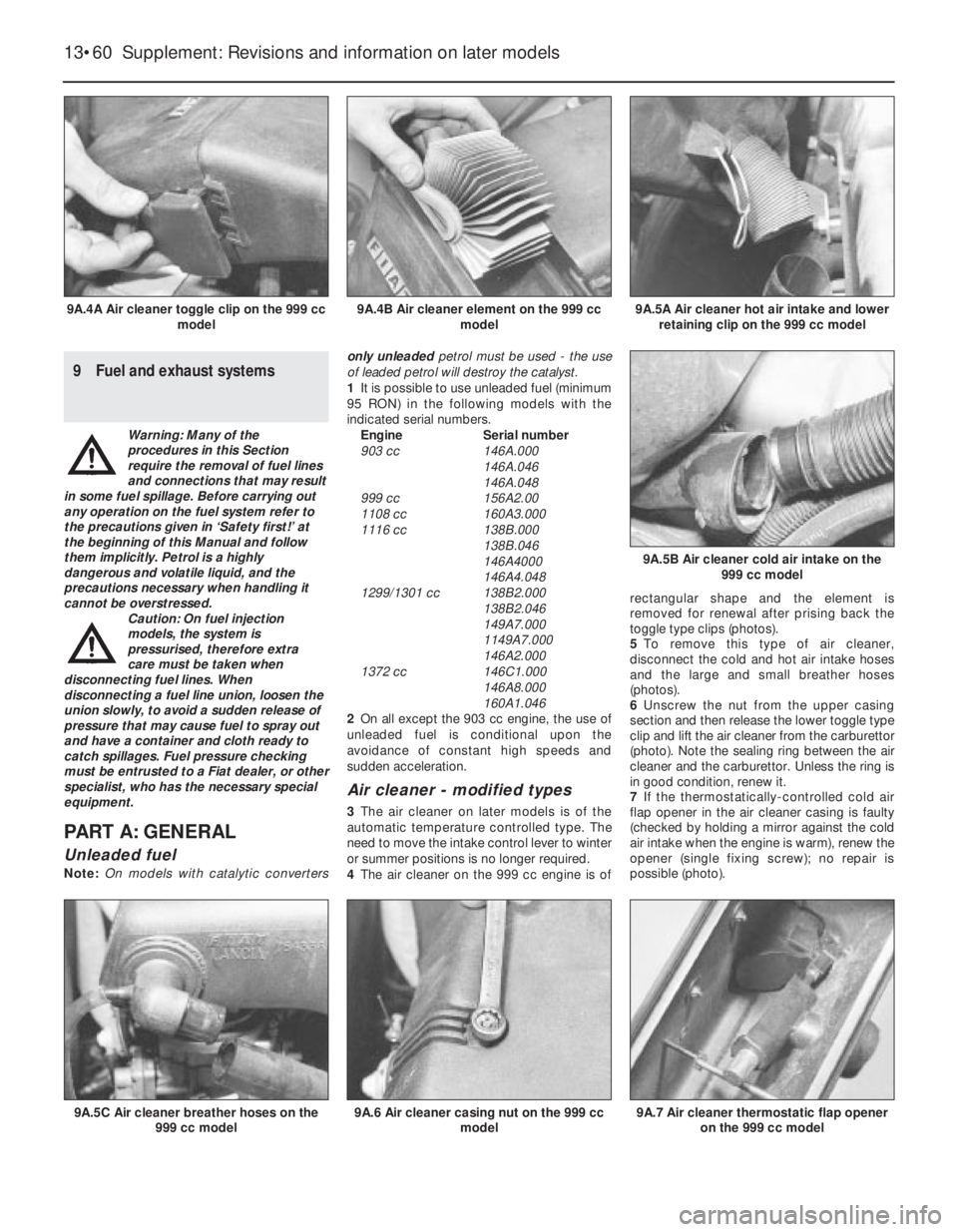
4The air cleaner on the 999 cc engine is ofrectangular shape and the element is
removed for renewal after prising back the
toggle type clips (photos).
5To remove this type of air cleaner,
disconnect the cold and hot air intake hoses
and the large and small breather hoses
(photos).
6Unscrew the nut from the upper casing
section and then release the lower toggle type
clip and lift the air cleaner from the carburettor
(photo). Note the sealing ring between the air
cleaner and the carburettor. Unless the ring is
in good condition, renew it.
7If the thermostatically-controlled cold air
flap opener in the air cleaner casing is faulty
(checked by holding a mirror against the cold
air intake when the engine is warm), renew the
opener (single fixing screw); no repair is
possible (photo).
13•60 Supplement: Revisions and information on later models
9A.7 Air cleaner thermostatic flap opener
on the 999 cc model9A.6 Air cleaner casing nut on the 999 cc
model9A.5C Air cleaner breather hoses on the
999 cc model
9A.5B Air cleaner cold air intake on the
999 cc model
9A.5A Air cleaner hot air intake and lower
retaining clip on the 999 cc model9A.4B Air cleaner element on the 999 cc
model9A.4A Air cleaner toggle clip on the 999 cc
model
Page 186 of 303
8The air cleaner on the 1116 cc and
1299/1301 cc engine is of circular type.
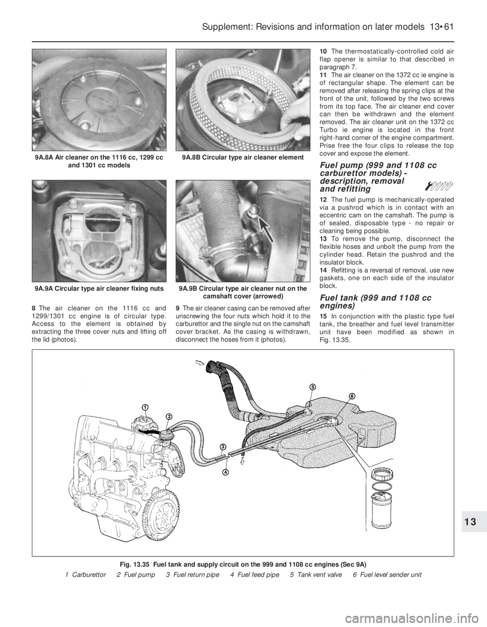
Access to the element is obtained by
extracting the three cover nuts and lifting off
the lid (photos).9The air cleaner casing can be removed after
unscrewing the four nuts which hold it to the
carburettor and the single nut on the camshaft
cover bracket. As the casing is withdrawn,
disconnect the hoses from it (photos).10The thermostatically-controlled cold air
flap opener is similar to that described in
paragraph 7.
11The air cleaner on the 1372 cc ie engine is
of rectangular shape. The element can be
removed after releasing the spring clips at the
front of the unit, followed by the two screws
from its top face. The air cleaner end cover
can then be withdrawn and the element
removed. The air cleaner unit on the 1372 cc
Turbo ie engine is located in the front
right-hand corner of the engine compartment.
Prise free the four clips to release the top
cover and expose the element.
Fuel pump (999 and 1108 cc
carburettor models) -
description, removal
and refitting
Á
12The fuel pump is mechanically-operated
via a pushrod which is in contact with an
eccentric cam on the camshaft. The pump is
of sealed, disposable type - no repair or
cleaning being possible.
13To remove the pump, disconnect the
flexible hoses and unbolt the pump from the
cylinder head. Retain the pushrod and the
insulator block.
14Refitting is a reversal of removal, use new
gaskets, one on each side of the insulator
block.
Fuel tank (999 and 1108 cc
engines)
15In conjunction with the plastic type fuel
tank, the breather and fuel level transmitter
unit have been modified as shown in
Fig. 13.35.
Supplement: Revisions and information on later models 13•61
9A.9A Circular type air cleaner fixing nuts9A.9B Circular type air cleaner nut on the
camshaft cover (arrowed)
9A.8B Circular type air cleaner element9A.8A Air cleaner on the 1116 cc, 1299 cc
and 1301 cc models
Fig. 13.35 Fuel tank and supply circuit on the 999 and 1108 cc engines (Sec 9A)
1 Carburettor 2 Fuel pump 3 Fuel return pipe 4 Fuel feed pipe 5 Tank vent valve 6 Fuel level sender unit
13
Page 187 of 303
PART B:
CARBURETTOR MODELS
Carburettor (Weber 32 TLF) -
description
Warning: Refer to the beginning
of this Section before starting
any work.
1This carburettor is used on the 999 cc
engine and is of the single venturi
downdraught type, with a manually-operated
choke (cold start).
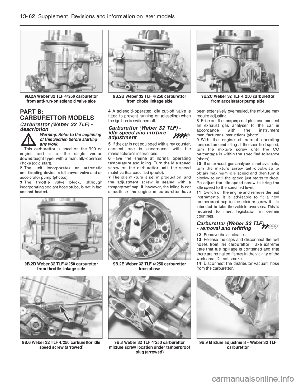
2The unit incorporates an automatic
anti-flooding device, a full power valve and an
accelerator pump (photos).
3The throttle valve block, although
incorporating coolant hose stubs, is not in fact
coolant-heated.4A solenoid-operated idle cut-off valve is
fitted to prevent running-on (dieseling) when
the ignition is switched off.
Carburettor (Weber 32 TLF) -
idle speed and mixture
adjustment
¢
5If the car is not equipped with a rev counter,
connect one in accordance with the
manufacturer’s instructions.
6Have the engine at normal operating
temperature and idling. Turn the idle speed
screw on the carburettor until the speed
matches that specified (photo).
7The idle mixture is set in production, and
the adjustment screw is sealed with a
tamperproof cap. If, however, the idling is not
smooth or the engine or carburettor havebeen extensively overhauled, the mixture may
require adjusting.
8Prise out the tamperproof plug and connect
an exhaust gas analyser to the car in
accordance with the instrument
manufacturer’s instructions (photo).
9With the engine at normal operating
temperature and idling at the specified speed,
turn the mixture screw until the CO
percentage is within the specified tolerance
(photo).
10If an exhaust gas analyser is not available,
turn the mixture screw anti-clockwise to
obtain maximum idle speed and then turn it
clockwise until the speed just starts to drop.
Re-adjust the idle speed screw to bring the
idle speed to the specified level.
11Switch off the engine and remove the test
instruments. It is advisable to fit a new
tamperproof cap to the mixture screw if it is
intended to take the vehicle overseas. This is
required to meet legislation in certain
countries.
Carburettor (Weber 32 TLF)
- removal and refitting ª
12Remove the air cleaner.
13Release the clips and disconnect the fuel
hoses from the carburettor. Take extreme
care that fuel spillage is contained and that
there are no naked flames in the vicinity of the
work area. Do not smoke.
14Disconnect the distributor vacuum hose
from the carburettor.
13•62 Supplement: Revisions and information on later models
9B.9 Mixture adjustment - Weber 32 TLF
carburettor9B.8 Weber 32 TLF 4/250 carburettor
mixture screw location under tamperproof
plug (arrowed)9B.6 Weber 32 TLF 4/250 carburettor idle
speed screw (arrowed)
9B.2E Weber 32 TLF 4/250 carburettor
from above9B.2D Weber 32 TLF 4/250 carburettor
from throttle linkage side
9B.2C Weber 32 TLF 4/250 carburettor
from accelerator pump side9B.2B Weber 32 TLF 4/250 carburettor
from choke linkage side9B.2A Weber 32 TLF 4/250 carburettor
from anti-run-on solenoid valve side
Page 189 of 303
Float level - checking and adjustment
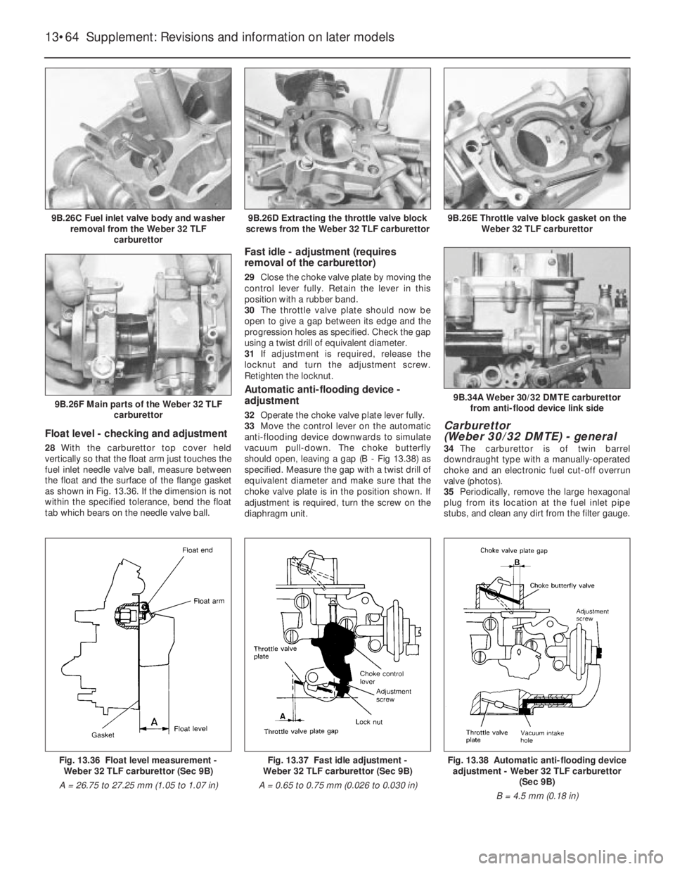
28With the carburettor top cover held
vertically so that the float arm just touches the
fuel inlet needle valve ball, measure between
the float and the surface of the flange gasket
as shown in Fig. 13.36. If the dimension is not
within the specified tolerance, bend the float
tab which bears on the needle valve ball.
Fast idle - adjustment (requires
removal of the carburettor)
29Close the choke valve plate by moving the
control lever fully. Retain the lever in this
position with a rubber band.
30The throttle valve plate should now be
open to give a gap between its edge and the
progression holes as specified. Check the gap
using a twist drill of equivalent diameter.
31If adjustment is required, release the
locknut and turn the adjustment screw.
Retighten the locknut.
Automatic anti-flooding device -
adjustment
32Operate the choke valve plate lever fully.
33Move the control lever on the automatic
anti-flooding device downwards to simulate
vacuum pull-down. The choke butterfly
should open, leaving a gap (B - Fig 13.38) as
specified. Measure the gap with a twist drill of
equivalent diameter and make sure that the
choke valve plate is in the position shown. If
adjustment is required, turn the screw on the
diaphragm unit.
Carburettor
(Weber 30/32 DMTE) - general
34The carburettor is of twin barrel
downdraught type with a manually-operated
choke and an electronic fuel cut-off overrun
valve (photos).
35Periodically, remove the large hexagonal
plug from its location at the fuel inlet pipe
stubs, and clean any dirt from the filter gauge.
13•64 Supplement: Revisions and information on later models
Fig. 13.37 Fast idle adjustment -
Weber 32 TLF carburettor (Sec 9B)
A = 0.65 to 0.75 mm (0.026 to 0.030 in)Fig. 13.38 Automatic anti-flooding device
adjustment - Weber 32 TLF carburettor
(Sec 9B)
B = 4.5 mm (0.18 in)Fig. 13.36 Float level measurement -
Weber 32 TLF carburettor (Sec 9B)
A = 26.75 to 27.25 mm (1.05 to 1.07 in)
9B.26F Main parts of the Weber 32 TLF
carburettor
9B.26E Throttle valve block gasket on the
Weber 32 TLF carburettor9B.26D Extracting the throttle valve block
screws from the Weber 32 TLF carburettor9B.26C Fuel inlet valve body and washer
removal from the Weber 32 TLF
carburettor
9B.34A Weber 30/32 DMTE carburettor
from anti-flood device link side
Page 191 of 303
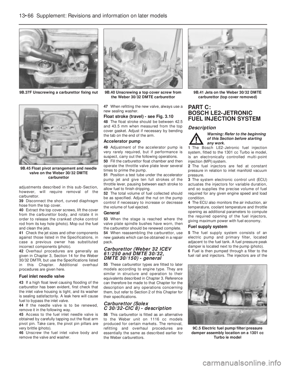
adjustments described in this sub-Section,
however, will require removal of the
carburettor.
39Disconnect the short, curved diaphragm
hose from the top cover.
40Extract the top cover screws, lift the cover
from the carburettor body, and rotate it in
order to release the cranked choke control
rod from its key hole (photo). Mop out the fuel
and clean the jets.
41Check the jet sizes and other components
against those listed in the Specifications, in
case a previous owner has substituted
incorrect components (photo).
42Overhaul procedures are generally as
given in Chapter 3, Section 14 for the Weber
30/32 DMTR, but use the Specifications listed
in this Chapter. Additional overhaul
procedures are given here.
Fuel inlet needle valve
43If a high float level causing flooding of the
carburettor has been evident, first check that
the inlet valve housing is tight, and its washer
is sealing satisfactorily. A leak here will cause
fuel to bypass the inlet valve.
44If the needle valve is to be renewed,
remove it in the following way.
45Access to the fuel inlet needle valve is
obtained by carefully tapping out the float arm
pivot pin. Take care, the pivot pin pillars are
very brittle (photo).
46Unscrew the fuel inlet valve body and
remove the valve and washer.47When refitting the new valve, always use a
new sealing washer.
Float stroke (travel) - see Fig. 3.10
48The float stroke should be between 42.5
and 43.5 mm when measured from the top
cover gasket. Adjust if necessary by bending
the tab on the end of the arm.
Accelerator pump
49Adjustment of the accelerator pump is
very rarely required, but if performance is
suspect, carry out the following operations.
50Fill the carburettor float chamber and then
operate the throttle valve plate lever several
times to prime the pump.
51Position a test tube under the accelerator
pump jet and give ten full strokes of the
throttle lever, pausing between each stroke to
allow fuel to finish dripping.
52The total volume of fuel collected should
be as specified. Adjust the nut on the pump
control if necessary to increase or decrease
the volume of fuel ejected.
General
53When the stage is reached where the
valve plate spindle bushes have worn, then
the carburettor should be renewed complete.
54When reassembling the carburettor, use
new gaskets which can be obtained in a repair
pack.
Carburettor (Weber 32 ICEV
61/250 and DMTE 30/32,
DMTE 30/150) - general
55These carburettor types are fitted to later
models according to engine type. They are
similar in structure and operation to their
equivalents described in Chapter 3. Reference
can therefore be made to that Chapter for the
description and any operations concerning
them, but refer to Section 2 of this Chapter for
their specifications.
Carburettor (Solex
C 30/32-CIC 8) - description
56This carburettor is fitted as an alternative
to the Weber unit on 1116 cc models
produced for certain markets. The removal,
refitting and overhaul procedures are
essentially the same as described earlier for
the Weber carburettors.
PART C:
BOSCH LE2-JETRONIC
FUEL INJECTION SYSTEM
Description
Warning: Refer to the beginning
of this Section before starting
any work.
1The Bosch LE2-Jetronic fuel injection
system, fitted to the 1301 cc Turbo ie model,
is an electronically controlled multi-point
injection (MPi) system.
2The fuel injectors are fed at constant
pressure in relation to inlet manifold vacuum
pressure.
3The system electronic control unit (ECU)
actuates the injectors for variable duration,
and so supplies the precise volume of fuel
required for any given engine speed and load
condition.
4The ECU also monitors the air induction, air
temperature, coolant temperature and throttle
opening as additional parameters to compute
the required opening of the fuel injectors,
giving maximum power with fuel economy.
Fuel supply system
5The fuel supply system consists of an
electric pump and primary filter, located
adjacent to the fuel tank. A fuel pressure peak
damper is located next to the pump (photo).
6Fuel is then pumped through a filter to the
fuel rail and injectors. The injectors are of the
13•66 Supplement: Revisions and information on later models
9C.5 Electric fuel pump/filter/pressure
damper assembly location on a 1301 cc
Turbo ie model
9B.41 Jets on the Weber 30/32 DMTE
carburettor (top cover removed)
9B.45 Float pivot arrangement and needle
valve on the Weber 30/32 DMTE
carburettor
9B.40 Unscrewing a top cover screw from
the Weber 30/32 DMTE carburettor9B.37F Unscrewing a carburettor fixing nut