1982 VOLVO 700 engine oil
[x] Cancel search: engine oilPage 39 of 168
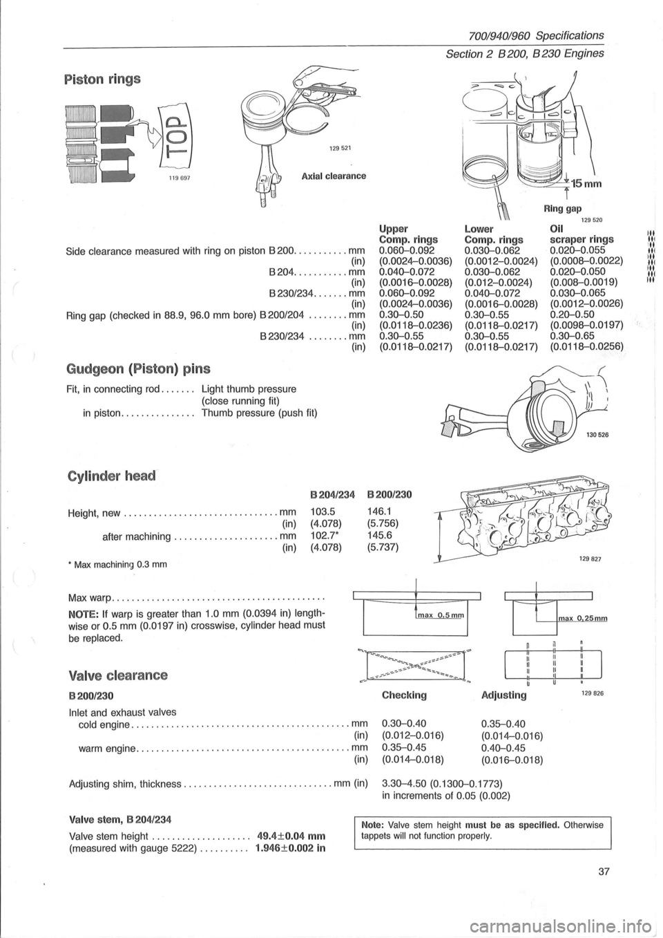
Piston rings
129521
Axial clearance
Side clearance measured with ring on piston 8200 ........... mm
(in)
8204 ........... mm
(in)
8230/234 ....... mm (in)
Ring gap (checked
in 88.9, 96.0 mm bore) 8200/204 ........ mm (in) 8230/234 ........ mm
Gudgeon (Piston) pins
Fit, in connecting rod. . . . . .. Light thumb pressure
(close running fit) (in)
in piston.
. . . . . . . . . . . . .. Thumb pressure (push fit)
Cylinder head-
Height, new ............................... mm
(in)
after machining
..................... mm
(in)
• Max machining 0.3 mm
B204/234
103.5
(4.078)
102.7*
(4.078)
Max warp .......................................... .
NOTE: If warp is greater than 1.0 mm (0.0394 in) length
wise or 0.5 mm (0.0197 in) crosswise, cylinder head must
be replaced.
Valve clearance
B200/230
Inlet and exhaust valves
cold
engine ............................................ mm
(in)
warm engine
........................................... mm
(in)
70019401960 Specifications
Section 2 B 200, B 230 Engines
Upp er Compo rings 0.060-0.092
(0.0024-0.0036)
0.040-0.072 (0.0016-0.0028)
0.060-0.092 (0.0024-0.0036)
0.30-0.50
(0.0118--0.0236)
0.30-0.55
(0.0118--0.0217)
B200/230
146.1
(5.756)
145.6
(5.737)
Checking
0.30-0.40 (0.012-0.Q16)
0.35--0.45 (0.014-0.018)
Lower Compo rings 0.030-0.062 (0.0012-0.0024)
0.030-0.062 (0.012-0.0024)
0.040-0.072 (0.0016-0.0028)
0 .30-0.55
(0.0118--0.0217)
0.30-0.55
(0.0118--0.0217)
Adjusting
0.35--0.40
(0.014-0.016)
0.40-0.45 (0.016-0.018)
Ring gap 129520 Oil scraper rings 0.020-0.055
(0.0008--0.0022)
0.020-0.050 (0.008--0.0019)
0.030-0.065 (0.0012-0.0026)
0.20-0.50 (0.0098--0.0197)
0.30-0.65 (0.0118--0.0256)
max o 25mm
129 826
Adjusting shim, thickness .............................. mm (in) 3.30-4.50 (0.1300-0.1773)
in increments of 0.05 (0.002)
Valve stem, B 204/234
Valve stem height . . . . . . . . . . . . . . . . . . .. 49.4±0.04 mm
(measured with gauge 5222) . . . . . . . . .. 1.946±0.002 in
Note: Valve stem height must be as specified. Otherwise
tappets will not function properly.
37
III III
ill III ill
IN liN
t·
Page 43 of 168
(
70019401960 Specifications
Section
2 B 200, B 230 Engines
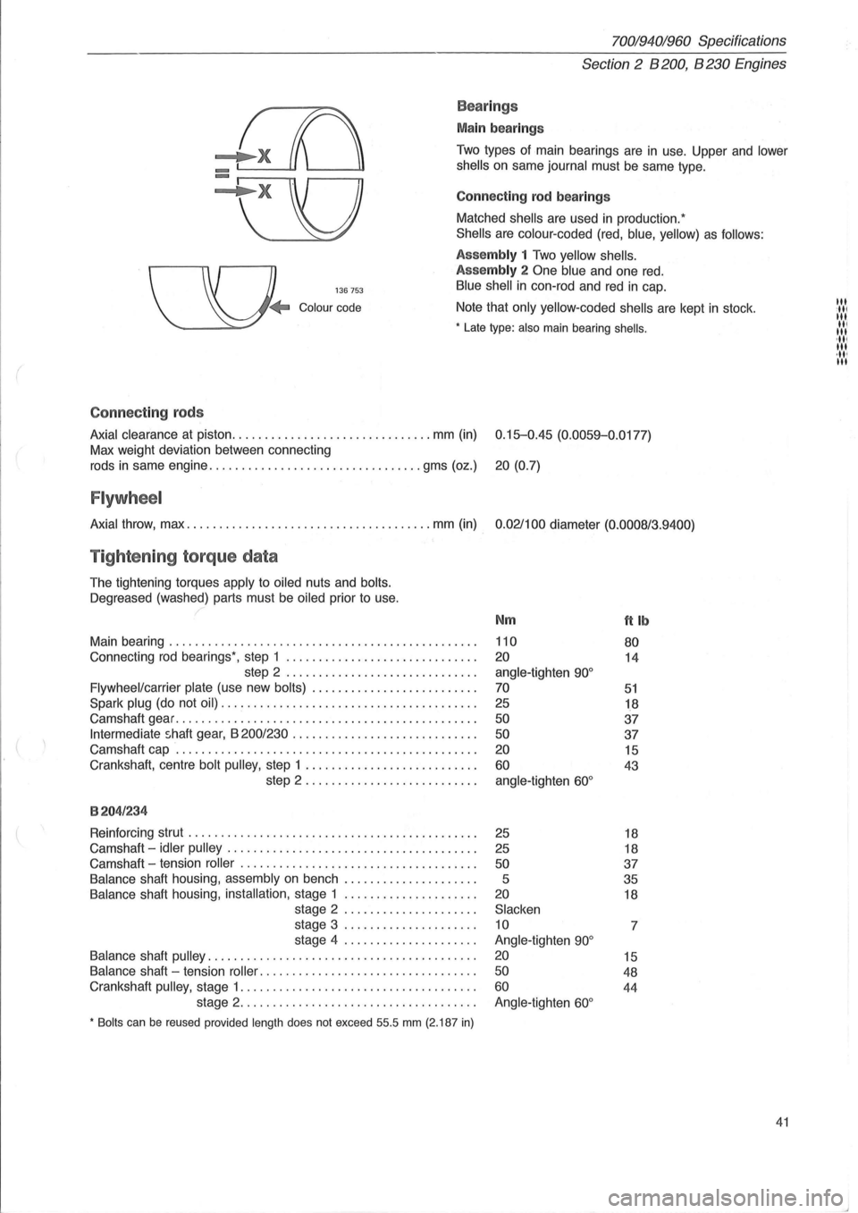
Bea rings
Main bearings
Two types of main bearings are in use. Upper and lower
shells
on same journal must be same type.
Connect
ing rod bearings
Matched
shells are used in production:
Shells are colour -coded (red, blue, yellow) as follows:
136753
Assembly 1 Two yellow shells.
Assembly
2 One blue and one red.
Blue shell in con-rod and red in cap.
Colour code Note that only yellow-coded shells are kept in stock .
• Late type: also main bearing shells .
Connect ing rods
Axial clearance at piston ............................... mm (in) 0.15-0.45 (0.0059-0.0177)
Max weight deviation between connecting
rods
in same engine ................................. gms (oz.) 20 (0.7)
Flywheel
Axial throw, max ...................................... mm (in) 0.021100 diameter (0.0008/3.9400)
Tightening torque data
The tightening torques apply to oiled nuts and bolts.
Oegreased
(washed) parts must be oiled prior to use.
Main bearing
............................................... .
Connecting
rod bearings', step 1 ............................. .
step 2
............................. .
Flywheel/carrier plate (use new bolts) ...................... ... .
Spark plug (do not oil) ....................................... .
Camshaft gear
.............................................. .
Intermediate shaft gear, B 200/230 ............................ .
Camshaft cap
.............................................. .
Crankshaft, centre
bolt pulley, step 1 .......................... .
step 2 .
.. ....................... .
8204/234
Reinforcing strut ............................................ .
Camshaft -
idler pulley ...................................... .
Camshaft -tension
roller .................................... .
Balance shaft housing, assembly on bench .................... .
Balance shaft housing, installation, stage 1 .................... .
stage 2
.................... .
stage 3
.................... .
stage 4
.................... .
Balance shaft pulley ......................................... .
Balance shaft -tension roller .. ............................... .
Crankshaft
pulley, stage 1 .................................... .
stage 2
.................................... .
• Bolts can be reused provided length does not exceed 55.5 mm (2.187 in)
Nm
110
20
angle-tighten 90°
70
25
50
50
20
60
angle-tighten 60°
25
25
50
5
20
Slacken
10
Angle-tighten
90°
20
50
60
Angle-tighten 60°
ftlb
80
14
51
18
37
37
15
43
18
18
37
35
18
7
15
48
44
41
III :11' III II, III 'III III ,11' III
Page 44 of 168
70019401960 Specifications
Section 2 B 200, B 230 Engines
8204/234
Cam carrier (centre fasteners) . . . . . . . . . . . . . . . . . . . . . . . . . . . . . . . . . 20 15
Oil pump. . . . . . . . . . . . . . . . . . . . . . . . . . . . . . . . . . . . . . . . . . . . . . . . . . . . 11 7
Oil pump, inlet ..... , . . . . . . . . . . . . . . . . . . . . . . . . . . . . . . . . . . . . . . . . . 11 8
Oil pump -pulley, step 1 ..................................... 20 15
step 2 .......... . . . . . . . . . . . . . . . . . . . . . . . . . . . angle-tighten 60 °
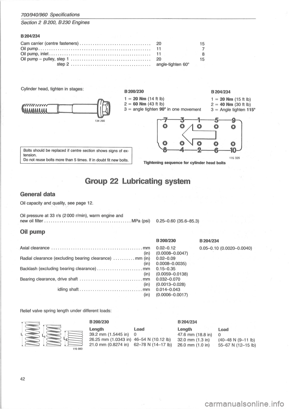
Cylinder head , tighten in stages : 8200/230
1 = 20 Nm (14 ft Ib)
2 = 60 Nm (43 ft Ib)
3 = angle tighten 90° in one movement
8204/234
1 = 20 Nm (15 ft Ib)
2 = 40 Nm (30 ft Ib)
3 = Angle tighten 115°
134 266 ~'--~3---1---5,---w9'~
Bolts should be replaced if centre section shows signs of ex
tension.
o ~O
o O~ 0
-~8,---..... 4-2 6 1
ns 125 Do not reuse bolts more than 5 times . If in doubt fit new bolls . Tightening sequence for cylinder head bolts
Group 22 Lubricating system
General data
Oil capacity and quality, see page 12.
Oil pressure at 33 rls (2000 rim in), warm engine and
new oil
filter ........ ; ............................... MPa (psi) 0.25-0.60 (35.6-85.3)
Oil pump
8200/230
0.02-0. 12
(0.0008-0.0047)
0 .
02-0.09
0.0008-0.0035)
0 .
15-0.35
(0.0059-0.0138)
0 .
032-0.070
(0.0013-0.028)
0 .
014-0.043
(0.0006-0.0017)
8204/234
Axial clearance ................ ... ....................... mm
(in)
Radial clearance (excluding bearing clearance) . ......... mm (in)
(in)
Backlash (excluding bearing clearance) ..................... mm
(in)
Bearing clearance , drive shaft
............................. mm
(in)
idling shaft .................... ......... mm
Relief valve spring length under different loads:
115083
42
8200/230
Length
39.2 mm (1.5445 in)
26.25 mm (1. 0343 in)
21.0 mm (0.8274 in) (in)
Load
o
46-54 N (10.12 Ib)
62-78 N (14-17 Ib)
0.05-0.
10 (0.0020-0.0040)
8204/ 234
Length
47.6 mm (18.8 in)
32.0 mm (1.3 in)
26 .0 mm (1.0 in)
Load
o
(40-48 N (9-11 Ib)
55-67 N (12-15 Ib)
Page 66 of 168
700/940/960 Specifications
Section 2' 8200,8230 Engines
Group 25 Intake and exhaust systems
Turbo engines
'-198~
Engine type .... ; ......... . , ............ .. .............
Charg~ pressure, at full load and ................... r/min
checking
.. ................... kPa (psi)
setting. . . . . . . . . . . . . . . . . . . . .
.. kPa (psi)
Charge air overpressure, switch opens at ....... kPa
(psi)
Charge air pressure, switch closes at ........... kPa (psi)
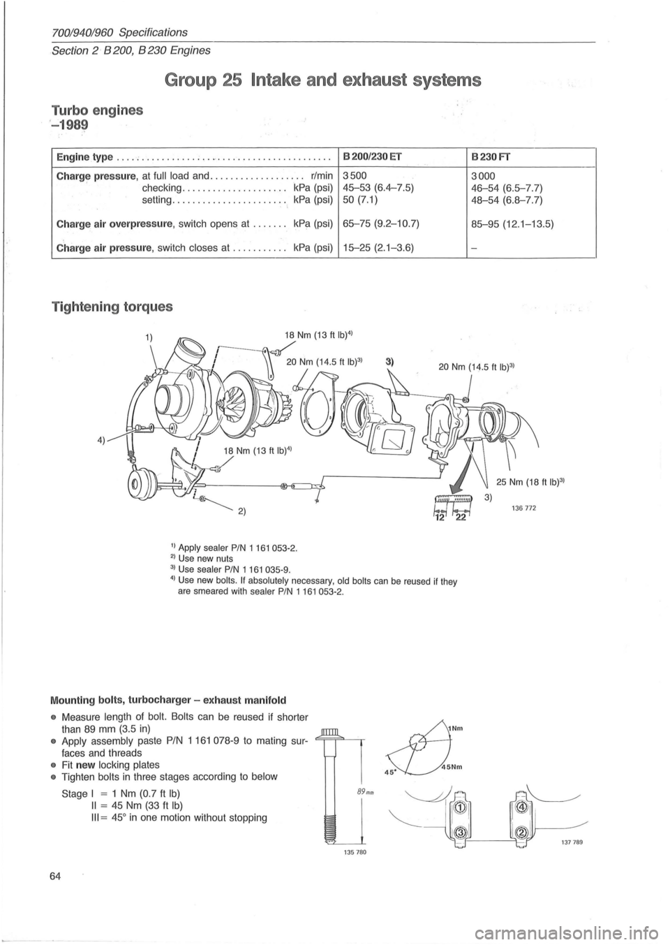
Tightening torques
4) 18 Nm (13 ft IW)
/
1) Apply sealer PIN 1 161 053-2. 2) Use new nuts
3) Use sealer PIN 1161 035-9.
8200/230 ET
3500
45-53 (6.4-7.5)
50 (7.1)
65-75 (9.2-10.7)
15-25 (2. 1-3.6)
3)
4) Use new boils. If absolutely necessary, old boils can be reused if they
are smeared with sealer PIN 1161053-2.
Mounting bolts, turbocharger -exhaust manifold
• Measure length of bolt. Bolts can be reused if shorter
than
89 mm (3.5 in)
• Apply assembly paste PIN 1 161 078-9 to mating sur-<=;==;=""-~
faces and threads
• Fit new locking plates
•
Tighten bolts in three stages according to below
64
Stage I = 1 Nm (0.7 ft Ib)
II = 45 Nm (33 ft Ib)
III = 45° in one motion without stopping
89mm
135780
~Nm
s::L).Nm
8230FT
3000
46-54 (6.5-7.7)
48-54 (6.8-7.7)
85-95 (12 .1-13.5)
-
136772
Page 69 of 168
70019401960 Specifications
Section
2 B 200, B 230 Engines
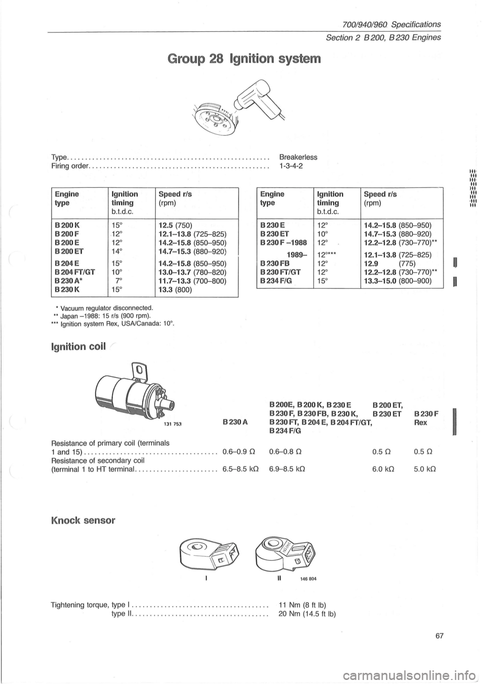
Group 28 Ignition system
Type. . . . . . . . . . . . . . . . . . . . . . . . . . . . . . . . . . . . . . . . . . . . . . . . . . . . . . . . Breakerless
Firing order. . . . . . . . . . . . . . . . . . . . . . . . . . . . . . . . . . . . . . . . . . . . . . . . . . 1-3-4-2
E
ngine Ignition
type timing
b.t.d.c.
B200K 15°
B200F .12°
B200E 12 °
B200ET 14°
B204E 15°
B204FT/GT 10°
B230A* 7°
B230K 15°
, Vacuum regulator disconnected . '* Japan -1988: 15 rls (900 rpm).
Speed rls
(rpm)
12.5
(750)
12.1- 13.8 (725-825)
14.2 -15.8
(850-950)
14.7-15.3 (880-920)
14.2-15.8 (850-950)
13.0-13.7 (780-820)
11.7-13.3 (700-800)
13.3 (800)
''* Ignition system Rex, USNCanada : 10°.
Ignition coil
Engine Ignition
type timing
b.t.d.c.
B230E 12°
B230ET 10°
B230F -1988 12 °
1989-12°***
B230FB 12 °
B230fT/GT 12°
B234F/G 15°
B200E,B200K,B230E
B 230 F, B 230 FB, B 230 K,
Speed rls
(rpm)
14.2-15.8
(850-950)
14.7 -15.3 (880-920)
12.2 -12.8 (730-770)* '
12.1-13.8 (725-825)
12.9 (775)
12.2 -12.8
(730-770)* *
13.3-15.0 (800-900)
B200ET,
B230ET B230F
131 7~1 B230A B 230 FT, B 204 E, B 204 FT/GT, Rex
B234 FIG
Resistance of primary coil (terminals
1 and 15) .................................... . 0.6-0.90 0.6-0.80 0.50 0.50
Resistance of secondary coil
(terminal
1 to HT terminal ...................... . 6.5-8. 5 kO 6 .9-8.5 kO 6 .0 kO 5 .0 kO
Knock sensor
II 146804
Tightening torque, type I . . . . . . . . . . . . . . . . . . . . . . . . . . . . . . . . . . . . . . 11 Nm (8 ft Ib)
type 11......... ............................. 20 Nm (14.5 It Ib)
67
I
I
I
til' ·ut til, til lit ·
t''''' '111 lit
Page 70 of 168
I
I
I
70019401960 Specifications
Section 2 B 200, B 230 Engines
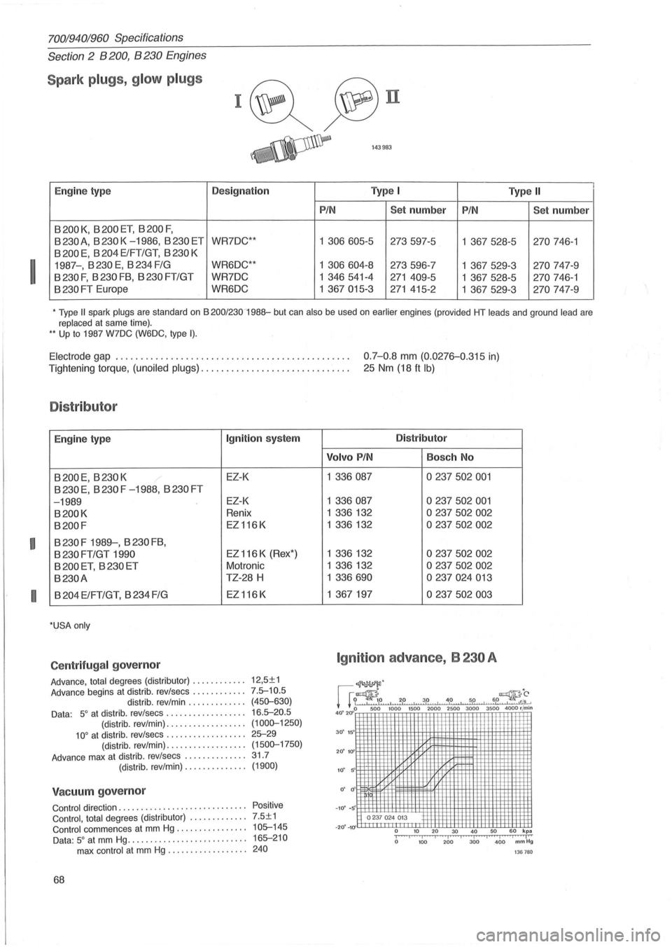
Spark plugs, g low plugs
I~~n
~ 143983
E ngin e type Designation Type I Type II
P
IN Se t number PIN Set number
B 200 K, B 200 ET, B 200 F,
B 230 A, B 230 K -1986, B 230 ET WR7DC " 1 306605-5 273597-5
1 367528-5 270 746-1
B 200 E, B 204 ElFT/GT, B 230 K
1987-, B
230 E, B 234 FIG WR6DC** 1 306604-8 273596-7 1 367529-3 270 747-9
B
230 F, B 230 FB, B 230 FT/GT WR7DC 1 346 541-4 271 409-5
1 367528-5 270 746-1
B 230 FT Europe WR6DC 1
367015-3 271 415-2
1 367529-3 270 747-9
• Type II spark plugs are standard on B 200/230 -1988-but can also be used on earlier engines (provided HT leads and ground lead are replaced at same time) . .. Up to 1987 W7DC (W6DC, type I).
Electrode gap .............................................. . 0.7-0.8 mm (0.0276-0.315 in)
25 Nm (18 ft Ib) Tightening torque, (unoiled plugs) ............................. .
Distributor
E ngine type Ignition system
B200E, B230K EZ-K
B
230 E, B 230 F -1988, B 230 FT
-1989
EZ- K
B200K Renix
B200F EZ 116 K
B
230 F 1989-, B 230 FB,
B 230 FT/GT 1990 EZ 116 K (Rex ')
B 200 ET , B 230 ET Motronic
B230A TZ-28 H
B
204 E/FT/GT, B 234 FIG EZ 116 K
'USA only
Centr ifugal governor
Advance, total degrees (distributor) . . . . . . . . . . .. 12,5± 1
Advance begins at distrib. rev/sees ............ 7.5-10.5
distrib . rev/min. . . . . . . . . . . .. (450-630) Data : 5° at distrib . rev/sees . . . . . . . . . . . . . . . . .. 16 .5-20.5 (distrib. rev/min) . . . . . . . . . . . . . . . . .. (1000-1250) 10° at distrib . rev/sees . . . . . . . . . . . . . . . . .. 25-29 (distrib . rev/min) .................. (1500-1750)
Advance max at distrib. rev/sees .............. 31.7
(distrib. rev/min) . . . . . . . . . . . . .. (1900)
Vacuum governor
Control direction ............... .. ........... . Control, total degrees (distributor) .......... .. . Control commences at mm Hg ............... .
Data : 5° at mm Hg . .. ....................... .
max control at mm Hg ........ .... ..... .
68
Positive
7.5±1 105-145
165-210
240
Distributor
Volvo PIN Bosch No
1
336087 0237502001
1 336087 0237502001
1 336 132 0237502002
1 336132 0237502002
1 336 132 0237502002
1 336 132 0237502002
1 336690 0237024013
1 367197 0237502003
Ignition advance, B 230 A
~.
rrr~,o , 2p , 3,0 , 4 ,0 , 5,0 , 6,0~;;. + l ' 0 500 1000 1500 2000 2500 3000 3500 4000 rl min
40.20"~mm Wmfmm ~mmfffi=mmm
o· Ii'
-10' -ft '0237 0 24 013
10 20 30 iii 100 200 40 50 60 kpa 3bo i 460 j mm iHg
13 6780
i
Page 72 of 168
70019401960 Specifications
Section'-2" B 28 Engine
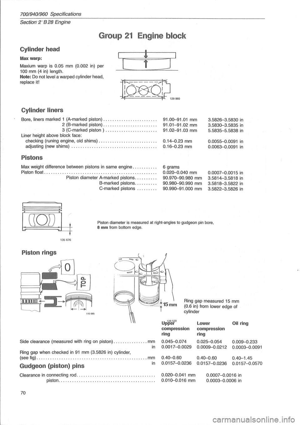
Group 21 Engine block
Cylinder head
Max warp:
Maxium warp is
0.05 mm (0.002 in) per
100 mm (4 in) length.
Note: Do not level a warped cylinder head,
replace it!
Cylinder liners
[
Bore, liners marked 1 (A-marked piston) ....................... .
2 (B-marked piston) ....................... .
3 (C-marked piston) ...................... .
Liner height above
block face:
checking (runing engine,
old shims) ....................... .. .
adjusting (new shims)
..................................... .
Pistons
Max weight difference between pistons in same engine .......... .
Piston
float ................................................. .
Piston diameter A-marked pistons
......... .
B-marked pistons
......... .
C-marked pistons
........ .
]
91.00-91.01 mm
91.01-91.02 mm
91.02-91.03 mm
0.14--0.23 mm
0.16-0.23 mm
6 grams
0.020-0.040 mm
90.970-90.980 mm
90.980-90.990 mm
90.990-91.000 mm
3.5826-3.5830 in
3.5830-3.5835 in
5.5835-5.5838 in
0.0055-0.0091 in
0.0063-0.0091 in
0.0007-0. 0015 in
3.5814-:3.5818 in
3.5818-3.5822 in
3.5822-3.5826 in
((0)) t
'" ~L-f
Piston diameter is measured at right-angles to gudgeon pin bore, S mm from bottom edge.
135676
Piston rings
/,
I 111111111 ~III
'--J 115085
Side clearance (measured with ring on piston) ............... mm
in
Ring gap when checked in 91 mm (3.5826 in) cylinder,
Ring gap measured 15 mm
(0.6 in) from lower edge of
cylinder
U 129520 pper
compression
ring
0.045-0.074
0.0017-0.0029
Lower Oil ring
compression
ring
0.025-0.054 0.009--0.233
0.0009--0.0212 0.0003-0.0091
(see fig) ................................................. mm 0.40-0.60 0.40-0.60 0.40-1.45
in 0.0157-0.0236 0.0157-0.0236 0.0157-0.0570 Gudgeon (piston) pins
Clearance in connecting rod. . . . . . . . . . . . . . . . . . . . . . . . . . . . . . . . . . . 0.020-0.041 mm
piston. . . . . . . . . . . . . . . . . . . . . . . . . . . . . . . . . . . . . . . . . . .
0.010-0.016 mm
70 0.0007-0.0016
in
0.0003-0.0006 in
Page 75 of 168
{
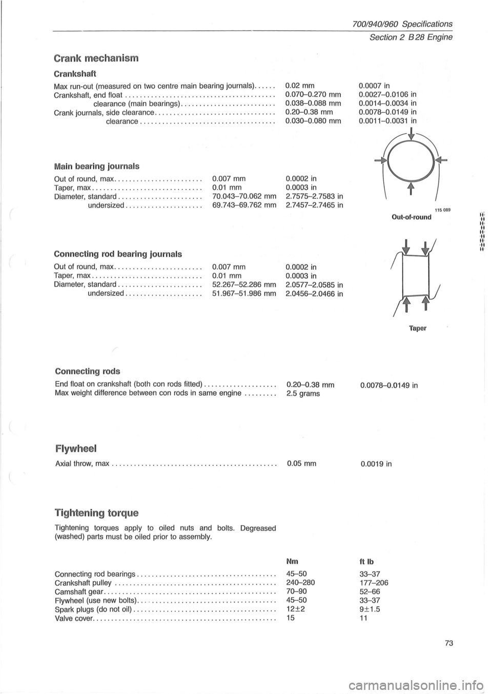
Crank mec ha ni sm
Cr ank sh aft
Max run-out (measured on two centre main bearing journals) ..... .
Crankshaft, end float
........................................ .
clearance (main bearings) ......................... .
Crank
journals, side clearance ...........•.................... .
clearance .................................... .
M ain bea rin g journ als
Out of round, max ....................... .
Taper, max
...... ....................... .
Diameter, standard ...
................... .
undersized
.................... .
Conne cting rod b ea ring journ als
Out of round, max ....................... .
Taper, max
............................. .
Diameter, standard
...................... .
undersized
.................... .
C onnec tin g rods
0 .007 mm
0.01 mm
70.043-70.062 mm
69 .743-69.762 mm
0.007 mm
0.01 mm
52.267-52 .286 mm
51.967-51.986 mm
End
float on crankshaft (both can rods fitted) ................... .
Max weight difference between can rods
in same engine ........ .
Flywh eel
0.02 mm
0 .070-0.270 mm
0.038-0.088 mm
0.20-0.38 mm
0 .030-0.080 mm
0.0002 in
0.0003 in
2.7575-2.7583 in
2 .7457-2.7465 in
0.0002 in
0.0003 in
2.0577-2.0585 in
2.0456-2.0466 in
0.20-0.38 mm
2.5 grams
Axial throw, max . . . . . . . . . . . . . . . . . . . . . . . . . . . . . . . . . . . . . . . . . . . . . 0 .05 mm
T ig hte nin g torq ue
Tightening torques apply to oiled nuts and bolts. Degreased
(washed) parts must be
oiled prior to assembly.
Connecting rod bearings ................. .......... ..... ..... .
Crankshaft
pulley . ........ .......... ........................ .
Camshaft gear
................................. ............. .
Flywheel (use new bolts) ... -................................. .
Spark plugs (do not oil) ...................................... .
Valve cover ......... .................................... .... .
Nm
45-50
240-280
70-90
45-50
12±2
15
70019401960 Specifications
Section 2 B 28 Engine
0 .0007 in
0.0027 -0.0106 in
0.0014-0.0034 in
0.0078-0 .0149 in
0 .0011-0.0031 in
Out-of-round
Taper
0 .0078-0.0149 in
0.0019 in
ttlb
33-37
177 -206
52-66
33-37
9±1.5
11
115089
73
t't'. -II II· II II' ,II II'
,II II'