1982 VOLVO 700 engine oil
[x] Cancel search: engine oilPage 143 of 168
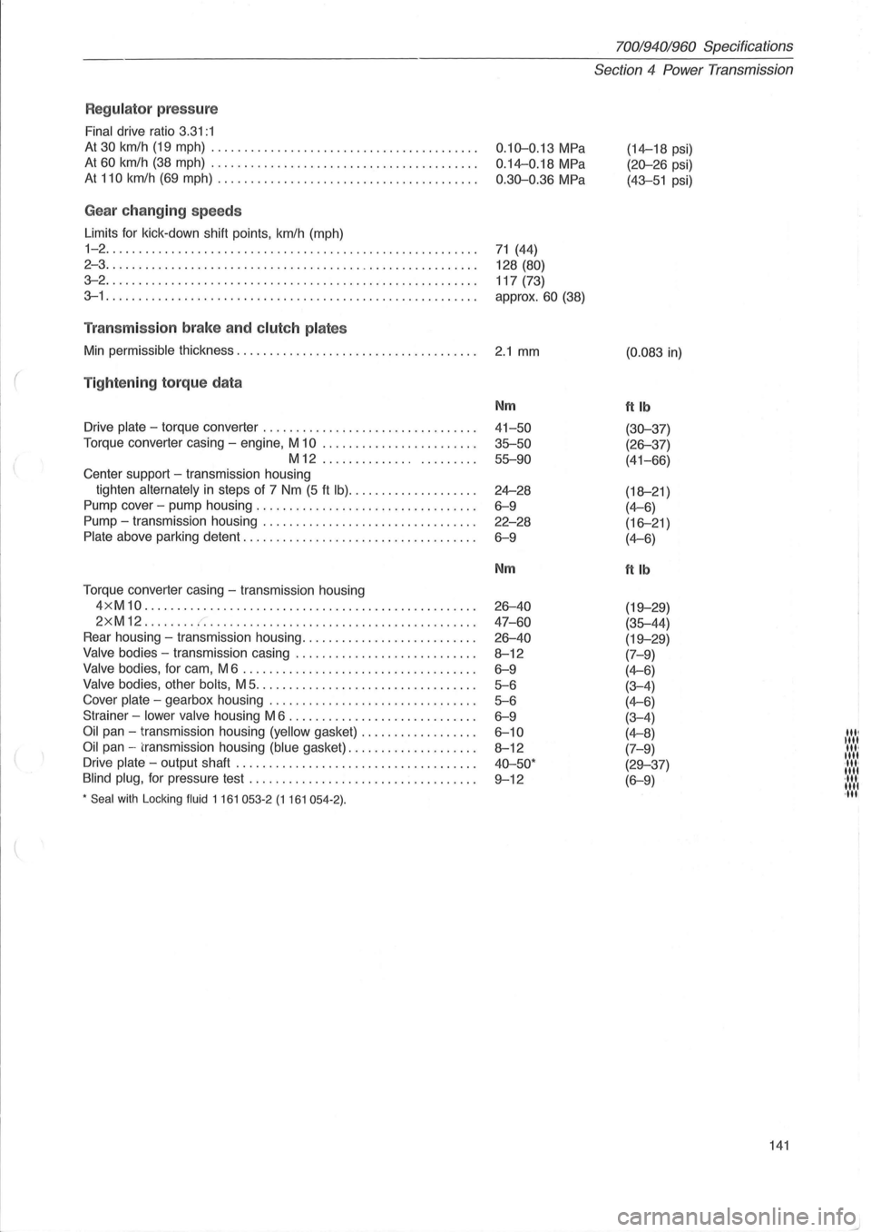
Regulator press ure
Final drive ratio 3.31:1
At 30 km/h (19 mph) ........................................ .
At 60 km/h (38 mph) ....... ................................. .
At 110 km/h (69 mph) ....................................... .
Gea r ch anging speeds
Limits for kick -down shift points , km/h (mph)
1-2 ........................................................ .
2 - 3
......... ............................................... .
3-2 ............................. ........................... .
3-1 ...................................................... .. .
Tran smiss io n brake an d clut ch pla tes
Min permissible thickness .................................. .. .
( Tig ht enin g to rq ue da ta
Drive plate - torque converter ....................... ......... .
Torque converter casing -engine, M
10 ....................... .
M12 ..................... ..
Center support -transmission housing
tighten
alternately in steps of 7 Nm (5 ft Ib) ................... .
Pump cover -pump housing
.................. ............... .
Pump -transmission housing ...
............................. .
Plate above parking detent ............................ .... ... .
Torque converter casing -transmission housing
4 x M
10 .................................................. .
2xM12 ....... . r. ............... ......................... .
Rear housing -transmission housing .......................... .
Valve bodies -transmission casing ........................... .
Valve bodies, for cam, M 6 ................................... .
Valve bodies, other bolis, M 5 ................................. .
Cover
plate - gearbox housing ............................... .
Strainer -
lower valve housing M 6 ......................... ... .
Oil pan - transmission housing (yellow gasket) ................. .
Oil pan -transmission housing (blue gasket) ................... .
Drive
plate - output shaft .... ............................. ... .
Blind plug, for pressure test ....................... .. ......... .
* Seal with Locking fluid 1 161 053-2 (1 161 054-2) .
0.10-0.13 MPa
0.14-0.18 MPa
0.30-0.36 MPa
71 (44)
128
(80)
117 (73)
approx.
60 (38)
2.1 mm
Nm
41-50
35-50 55-90
24-28
6-9
22-28
6-9
Nm
26-40
47 -60
26-40
8-12
6-9
5-6
5-6
6-9
6-10
8-12
40-50·
9-12
70019401960 Specifications
Section 4 Power Transmission
(14-18 psi)
(20-26 psi)
(43-51 psi)
(0.083 in)
ftlb
(30-37)
(26-37)
(41-66)
(18-21 )
(4-6)
(16-21)
(4-6)
ftlb
(19-29)
(35-44)
(19-29)
(7-9)
(4-6)
(3-4)
(4-6)
(3-4)
(4-8)
(7-9)
(29-37)
(6-9)
141
'", "" '", "" ·11"
"" ·11.· 1111 ,11'
Page 145 of 168
(
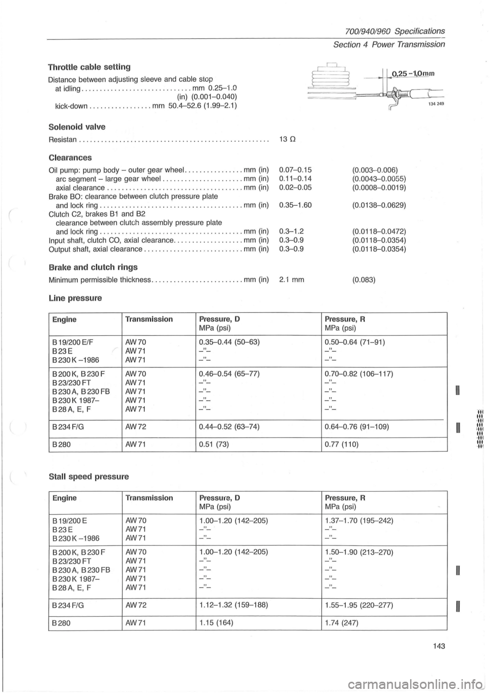
Throttl e cable se tting
Distance between adjusting sleeve and cable stop
at idling .............................. mm 0.25-i.O
(in) (0. 001-0.040)
kick-down ............. .... mm 50.4-52.6 (1.99-2.1)
Sol e n o id va lv e
Resistan . . . . . . . . . . . . . . . . . . . . . . . . . . . . . . . . . . . . . . . . . . . . . . . . . . . . 13 0
C lea ra n ces
Oil pump : pump body -outer gear wheel. ............... mm (in)
arc segment -large gear wheel ...................... mm (in)
axial clearance ................................ ..... mm (in)
Brake BO: clearance between clutch pressure plate
and lock ring ....................................... mm (in)
Clutch C2, brakes B1 and B2
clearance between clutch assembly pressure plate
and lock ring ....................................... mm (in)
Input shaft, clutch CO, axial clearance ........... ... ..... mm (in)
Output shaft, axial clearance ................. .......... mm (in)
B ra ke a nd clutch ring s
0.07-0.15
0 .
11-0.14
0 .
02-0.05
0.35-1.60
0.3--1.2
0 .
3--0.9
0.3--0 .9
Minimum permissible thickness ..................... .... mm (in) 2.1 mm
Line pr ess ure
Engine Tra nsmi ssion Press ure, 0
MPa (psi)
B
19/200 ElF AW70 0.35-0.44
(50--63)
B23E AW71 "
B230K -1986 AW71 "
B200K, B230F AW70 0.46-0.54 (65-77)
B23/230FT AW71 "
B 230 A
, B 230 FB AW71 "
B230K 1987-AW71 "
B28A, E, F AW71 "
B234 FIG AW72 0.44-0
.52 (63--74)
B280
AW71 0.51 (73)
S tall spee d press ure
Engine T
ra n smi ssion Press ure, 0
MPa (psi)
B
19/200 E AW70 1.00--1.20 (142-205)
B23E AW71 "
B230K -1986 AW71 "
B 200 K, B 230 F AW70 1.00--1.20 (142-205)
B23/230 FT AW71 "
B 230 A, B 230 FB AW71 "
B230K 1987-AW71 "
B28A, E, F AW71 "
B234 FIG AW72 1.12
-1.32 (159-188)
B280 AW71 1
.15 (164)
7001940 1960 Specifications
Section
4 Power Transmission
025-10mm
(0.003 -0 .006)
(0.0043--0 .0055)
(0.0008-0.0019)
(0.0138-0.0629)
(0.0118-0.0472)
(0.0118-0.0354)
(0.0118-0 .0354)
(0.083)
Pres sur e, R
MPa (psi)
0.50--0 .64 (71-91)
"
"
0.70--0.82 (106-117)
"
"
"
"
0.64-0.76 (91-109)
0 .
77 (110)
Press ure, R
MPa (psi)
1.37-1.70 (195-242) "
"
1.50--1.90 (213-270)
- -
"
"
"
1 .55-1.95 (220--277)
1 .
74 (247)
-
143
I
I
I
I
Page 147 of 168
(
(
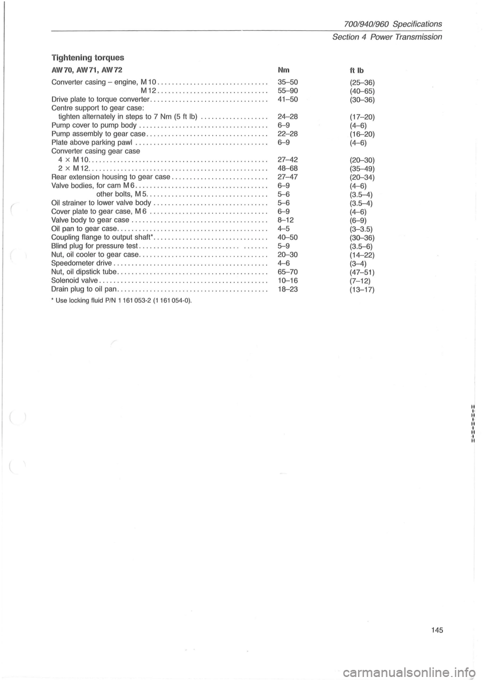
Tightening torques
AW70, AW71, AW72
Converter casing -engine, M 10 ...................... .. ...... .
M12 .................. ......... .. . .
Drive plate
to torque converter ................... ............. .
Centre support to gear case:
tighten alternately
in steps to 7 Nm (5 ft Ib) ............... ... .
Pump cover to pump body .......................... ......... .
Pump assembly to gear case .............. ................... .
Plate above parking pawl ............................. ....... .
Converter casing gear case
4
x M 10 ................................ ................. .
2 x M 12 ..
.............. ................................. .
Rear extension housing to gear case
.......................... .
Valve bodies, for cam M 6 .................................... .
other bolts, M 5 ...
.............................. .
Oil strainer to lower valve body ........... .. ............ ...... .
Cover plate
to gear case, M 6 ................................ .
Valve body to gear case ..................... .......... ..... . .
Oil pan to gear case .......... ........ ..................... .. .
Coupling flange
to output shaW .................... ........... .
Blind plug for pressure test. . . . . . . . . . . . . . . . . . . . . . . . . . . . . ..
... .
Nut, oil cooler to gear case .
.................................. .
Speedometer drive
................... .................. ..... .
Nut, oil dipstick tube
........ ................................. .
Solenoid valve
.................... .. ........................ .
Drain plug
to oil pan ........................................ . .
• Use locking fluid PIN 1161 053-2 (1161 054-0) .
Nm
35-50
55-90
41-50
24-28
6-9
22-28
6-9
27-42
48-68
27-47
6-9
5-6
5-6
6-9
8-12
4-5
40-50
5-9
20-30
4-6
65-70
10-16
18-23
70019401960 Specif ications
Section
4 Power Transmission
ftlb
(25-36)
(40-65)
(30-36)
(17-20)
(4-6)
(16-20)
(4-6)
(20-30)
(35-49)
(20-34)
(4-6)
(3.5-4)
(3.5-4)
(4-6)
(6-9)
(3-3.5)
(30-36)
(3.5-6)
(14-22)
(3-4)
(47-51)
(7-12)
(13-17)
145
II
" II ., II ' . .. • • ..
Page 150 of 168
700/940/960 Specifications
Section
4 Powe r Transmission
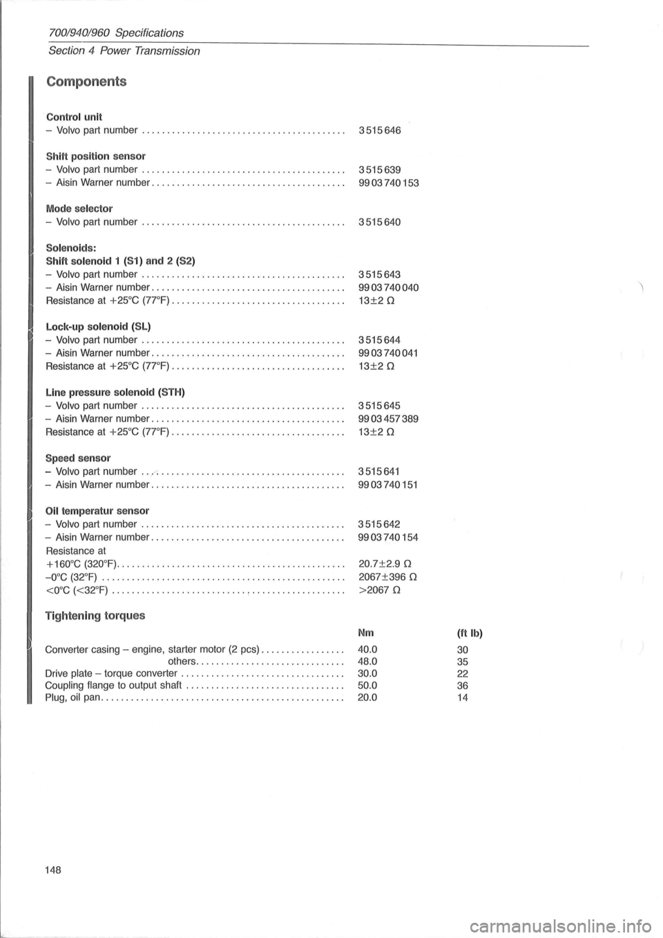
Components
Contro l unit
-Volvo part number . . . . . . . . . . . . . . . . . . . . . . . . . . . . . . . . . . . . . . . . . 3515646
ShiH position sensor
-Volvo part number. . . . . . . . . . . . . . . . . . . . . . . . . . . . . . . . . . . . . . . . . 3515639
- Aisin Warner number. . . . . . . . . . . . . . . . . . . . . . . . . . . . . . . . . . . . . . .
9903740153
Mode se lector
-Volvo part number . . . . . . . . . . . . . . . . . . . . . . . . . . . . . . . . . . . . . . . . . 3515640
Solenoids :
ShiH solenoid
1 (51) and 2 (52)
-Volvo part number. . . . . . . . . . . . . . . . . . . . . . . . . . . . . . . . . . . . . . . . . 3515643
- Aisin Warner number. . . . . . . . . . . . . . . . . . . . . . . . . . . . . . . . . . . . . . .
9903740040
Resistance at +25°C (7rF). . . . . . . . .. ... . . . . . . . . .. . . . . .. . . . . .. 13±20
Lock-up so lenoid (SL)
-Volvo part number. . . . . . . . . . . . . . . . . . . . . . . . . . . . . . . . . . . . . . . . . 3515644
- Aisin Warner number. . . . . . . . . . . . . . . . . . . . . . . . . . . . . . . . . . . . . . .
9903740041
Resistance at +25°C (7rF) ............. " . . . . . . . . . . . . .. . . .. . . 13±20
Line pressur e sole noid (5TH)
-Volvo part number. . . . . . . . . . . . . . . . . . . . . . . . . . . . . . . . . . . . . . . . . 3515645
- Aisin Warner number. . . . . . . . . . . . . . . . . . . . . . . . . . . . . . . . . . . . . . .
9903457389
Resistance at +25°C (7rF). . . . . . . . . . . . . ... . .. ..... . . . . ... .. . . 13±20
Speed sensor
-Volvo part number ... ..-: . . . . . . . . . . . . . . . . . . . . . . . . . . . . . . . . . . . . . 3515641
- Aisin Warner number. . . . . . . . . . . . . . . . . . . . . . . . . . . . . . . . . . . . . . .
9903740151
Oil te mp eratur senso r
-Volvo part number. . . . . . . . . . . . . . . . . . . . . . . . . . . . . . . . . . . . . . . . . 3515642
- Aisin Warner number. . . . . . . . . . . . . . . . . . . . . . . . . . . . . . . . . . . . . . .
9903740154
Resistance at
+160°C (320°F)......... .. .... . ......... ....... .............. 20.7±2.90
-O°C (32°F) .. . . . . . . .. . . . . . . . . . . . . . . .. . . . . . . .. . . .. . . . .. . . . . . . 2067±396 0
Tightening torques
Nm (ft Ib)
Converter casing -engine, starter motor (2 pcs) ................ . 40.0 30 others .............. ............... . 48.0 35
Drive plate -torque converter ................................ . 30.0 22
Coupling flange to output shaft ............................... . 50.0 36
Plug, oil pan ................................................ . 20.0 14
148
Page 153 of 168
(
70019401960 Specifications
Section
4 Power Transmission
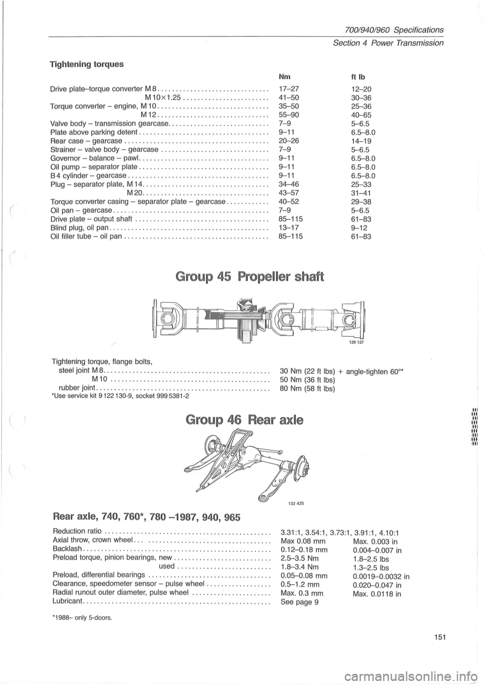
Tig ht enin g to rqu es
Nm ftlb
Drive plate-torque converter M 8 ................ .............. . 17-27 12-20
M10x 1.25 ......... .............. . 41-50 30-36
Torque converter -engine, M 10 .............................. . 35--50 25--36
M12 ........................ ...... . 55--90 40-65
Valve body -transmission gearcase ....................... .... . 7-9 5--6.5
Plate above parking detent ............ ............ ........... . 9--11 6.5--8 .0
Rear case -gearcase .............................. ......... . 20-26 14-19
Strainer - valve body -gearcase ................ ............ . . 7- 9
5--6.5
Governor -balance -pawl .......... ......................... . 9--11 6.5--8.0
Oil pump -separator plate .................. ................ . . 9--11 6.5--8 .0
B 4 cylinder -gearcase ...................................... . 9--11 6.5--8 .0
Plug -separator plate, M 14 .................................. . 34-46 25--33
M20 ....... ................ ...... ..... . 43- 57
31-41
Torque converter casing -separator plate -gearcase ........... . 40-52 29-38
Oil pan -gearcase .......................................... . 7-9 5--6.5
Drive plate -output shaft .................................... . 85--115 61-83
Blind plug, oil pan .................... ................. ...... . 13-17 9--12
Oil filler tube -oil pan ....................................... . 85--115 61-83
Group 45 Propeller shaft
/'
Tightening torque, flange bolts,
steel
joint M 8 ....................... ...... ..............•..
M10 ......................... .. ................ .
rubber joint ...................................... ......... . *Use service kit 9122130-9, socket 9995381 -2
ikd@
1 39 137
30 Nm (22 ft Ibs) + angle-tighten 60°*
50 Nm (36 ft Ibs)
80 Nm (58 ft Ibs)
Group 46 Rear axle
Rear axle , 740 , 760* , 780 -1987, 940 , 965
Reduction ratio ...................................... ....... . 3 .31:1, 3.54:1 , 3.73:1, 3 .91:1, 4 .10 :1 Axial throw, crown wheel ..................................... . Max 0.08 mm Max . 0.003 in Backlash ... ................................................ . 0 .12-0.18 mm 0 .004-0.007 in Preload torque, pinion bearings, new .......................... . 2.5--3.5 Nm 1.8-2.5 Ibs used ...... ... ................ . 1.8-3.4 Nm 1.3-2.5 Ibs
Preload, differential bearings ................................. . 0 .05--0 .08 mm 0.0019-0 .0032 in Clearance , speedometer sensor -pulse wheel .... .. ........... . 0 .5--1.2 mm 0 .020-0.047 in Radial runout outer diameter, pulse wheel ........ : .. : ......... . Max . 0.3 mm Max . 0.0118 in Lubricant ....... . ........................................... .
See page 9
*1988--only 5- doors.
151
III 1 .... 1 III ·111 III ·111 III ·111
Page 163 of 168
(
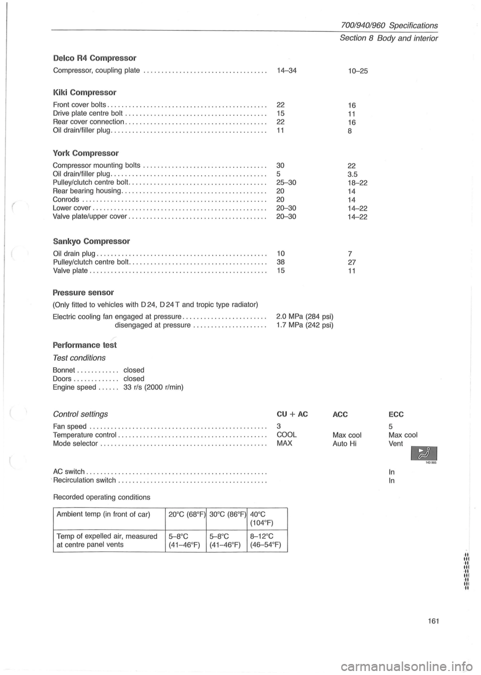
Delco R4 Compressor
Compressor, coupling plate ................................... 14-34
Kiki Compressor
Front cover bolts. . . . . . . . . . . . . . . . . . . . . . . . . . . . . . . . . . . . . . . . . . . . . 22
Drive
plate centre bolt . . . . . . . . . . . . . . . . . . . . . . . . . . . . . . . . . . . . . . . . 15
Rear cover connection. . . . . . . . . . . . . . . . . . . . . . . . . . . . . . . . . . . . . . . .
22
Oil drain/filler plug. . . . . . . . . . . . . . . . . . . . . . . . . . . . . . . . . . . . . . . . . . . . 11
York Compressor
Compressor mounting bolts ........................ .......... .
Oil drain/filler plug ........................................... .
Pulley/clutch centre bolt. ..................................... .
Rear bearing housing
.................................. ...... .
Con rods .
.................................................. .
Lower cover
........................................ .. ...... .
Valve plate/upper cover ...................................... .
Sankyo Compressor
30
5
25-30
20
20
20-30
20-30
Oil drain plug. . . . . . . . . . . . . . . . . . . . . . . . . . . . . . . . . . . . . . . . . . . . . . . . 10
Pulley/clutch
centre bolt. . . . . . . . . . . . . . . . . . . . . . . . . . . . . . . . . . . . . . . 38
Valve plate. . . . . . . . . . . . . . . . . . . . . . . . . . . . . . . . . . . . . . . . . . . . . . . . . . 15
Pressure sensor
(Only fitted to vehicles with D 24, D 24 T and tropic type radiator)
70019401960 Specifications
Section 8 Body and interior
10-25
16
11
16
8
22
3.5
18-22
14
14
14-22
14-22
7
27
11
Electric cooling fan engaged at pressure ....................... .
disengaged at pressure
.................... .
2.0 MPa (284 psi)
1 .7 MPa (242 psi)
Performance test
Test conditions
Bonnet . . . . . . . . . . .. closed
Doors . . . . . . . . . . . .. closed
Engine
speed. . . . .. 33 r/s (2000 r/min)
Control settings
Fan speed ........................... ...................... .
Temperature
control . ................................. ....... .
Mode
selector . ............................................. .
AC switch ............. ..................................... .
.
Recirculation switch ......................................... .
Recorded operating conditions
Ambient temp
(in front of car) 20°C (68°F) 30°C (86°F)
40°C
(104 °
F)
Temp of expelled air, measured 5-8°C 5-8°C 8-12°C
CU + AC
3
COOL
MAX
at centre panel vents
(41-46°F) (41-46 °F) (46-54°F)
ACC
Max cool
Auto Hi
ECC
5
Max cool
Vent
-In
In
143985
161
·11 lit ·11 lit ·11 lit ·11 III II