1982 VOLVO 700 engine oil
[x] Cancel search: engine oilPage 76 of 168
70019401960 Specifications
Section
2 B 28 Engine
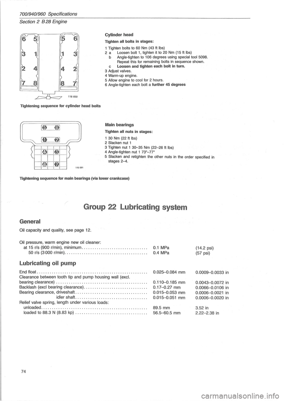
Cylinder head
Tighten all bolts in stages:
1 Tighten
bolts to 60 Nm (43 ft Ibs) 2 a Loosen bolt 1, tighten it to 20 Nm (15 ft Ibs) b Angle-tighten to 106 degrees using special tool 5098. Repeat this for remaining bolts in sequence shown.
118650
Tightening sequence for cylinder head bolts
L~~::~:~' ~I ~: I I I I
i61I~-
c Loosen and tighten each bolt in turn.
3 Adjust valves.
4
Warm-up engine.
5 Allow engine to cool for 2 hours.
6 Angle-tighten each bolt a further 45 degrees
Main bearings
Tighten all nuts in stages:
1
30 Nm (22 ft Ibs) 2 Slacken nut 1 3 Tighten nut 1 30-35 Nm (22-26 ft Ibs) 4 Angle-tighten nut 1 73°_77 °
1111-
i@1lf11 -
5 Slacken and retighten the other nuts in the order specified in stages 2-4.
---,---,---,---,-115091
Tightening sequence for main bearings (via lower crankcase)
Group 22 Lubricating system
General
Oil capacity and quality, see page 12.
Oil pressure, warm engine new oil cleaner:
at 15 rls (900 r/min), minimum .............................. .
50 rls (3000 r/min) .......... ....... ......... ............ .
Lubricating oil pump
End float ................................................... .
Clearance between tooth tip and pump housing wall (excl.
bearing clearance) .......................................... .
Backlash (excl bearing clearance) ................ ............. .
Bearing
clearance, driveshaft ................................. .
idler shaft. ................................ .
Relief valve spring, length under various loads:
unloaded
................................................. .
loaded to 88.3 N (8.83 kp) ............ ... .... .............. .
74
0.1 MPa
0.4 MPa
0 .
025-0.084 mm
0.110-0.185 mm
0 .17-0.27 mm
0.015-0.053 mm
0.015-0.051 mm
89.5 mm
56.5-60.5 mm
(14.2 psi)
(57 psi)
0.0009-0.0033 in
0.0043-0.0072 in
0.0066-0.0106 in
0 .0006-0.0021 in
0.0006-0.0020 in
3 .52 in
2.22-2.38 in
Page 86 of 168
70019401960 Specifications
Section
2 B 28 Engine
Group 28 Igni t ion system
Type. . . . . . . . . . . . . . . . . . . . . . . . . . . . . . . . . . . . . . . . . . . . . . . . . . . . . . . . Breakerless
Firing order. . . . . . . . . . . . . . . . . . . . . . . . . . . . . . . . . . . . . . . . . . . . . . . . . . 1-6 -3-5-2-4
E ngin e-
Ignition timing Spee d rls
type b.t.d.c .
(rpm)
8 28A*
10° 11.7 -13.3 (70D-800)
8 28 E* 10° 11.7 -13.3 (70D-800)
828F* 23° 41.7 (2500)
* Vacuum regulator disconnected.
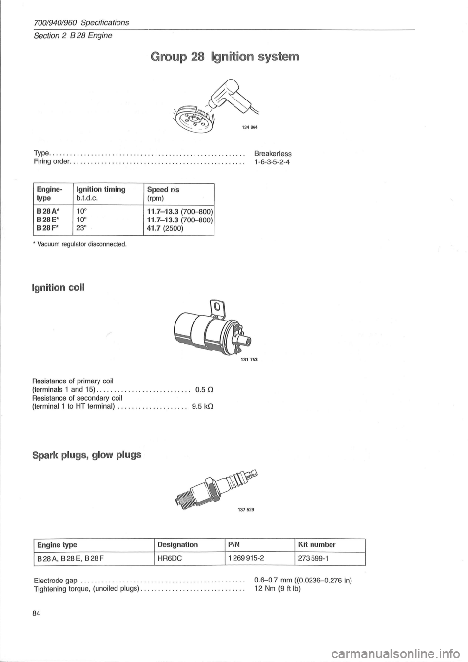
Ig niti on coil
/
Resistance of primary coil
(terminals
1 and 15). . . . . . . . . . . . . . . . . . . . . . . . . .. 0.5 0
Resistance of secondary coil
(terminal
1 to HT terminal) . . . . . . . . . . . . . . . . . . .. 9.5 kO
Spark plugs , glo w p lugs
E ngin e type D
es ign ation
B28A, B28E, B28F HR6DC
1317S3
PIN
1269915-2 Kit
number
273599-1
Electrode gap .............................................. .
Tightening torque,
(unoiled plugs) ............................. .
0.6-0.7 mm ((0.0236-0.276 in)
12 Nm (9 ft Ib)
84
Page 87 of 168
70019401960 Specifications
Section
2 B 28 Engine
Distributor
Eng ine type Ignit ion system Distributor
Volvo P IN Bosch No
B28A, B28E TSZ-4 1269191 0237402013
B28F TSZ-4 1269380 0237402017
B28A, E B28F
Bosch number ............... ............................... . 0237402013 0237402017
Volv o PIN ................................................... . 1
269 191 1 269380
Direction of rotat ion ............................ ... .......... . Clockwise
Clockwise
Resistance of impulse sender coil, [2 .........•................. 540-660
540-660
Air gap, rotor -stator , min ............. ...................... . 0.3 mm 0.3 mm
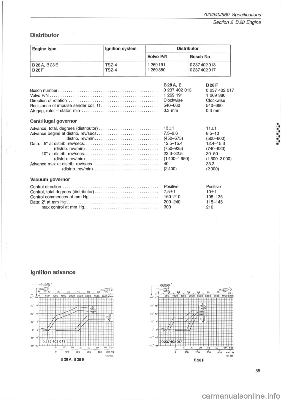
Centrifugal governor
Advance, total, degrees (distributor) ........ ................... .
Advance
begi ns at distrib. rev/sees ............................ .
distrib. rev/min
............................. .
Data:
5 ° at distr ib. rev/sees .............................. _ ... .
'III 13±1
11±1 '" III 7.fr-9.6 8.fr-10 ttl
(450-575)
(500-600) :':':': 12.fr-15.4 12.4-15.3 I'NI
(distrib. rev/min) ................................. . (750-925)
(740-920)
10° at distrib. rev/sees .................................. . 23.3-32.5 30-50
(distrib. rev/min)
................................. . (1400-1950)
(1800-3000)
Advance max at distrib . rev/sees ... .......................... . 40 33 .3
(distrib. rev/min)
............ ................. . (2400)
(2000)
Vacuum governor
Control direction ............................................ . Positive
Positive
Contro l, total
degrees (distributor) ............................. . 7,5±1 10±1
Control
commences at mm Hg ............................... . 160-210 10fr-135
Data: 2° at mm Hg ......................................... . . 200-240 11 fr-145
max control at mm Hg .................................. . 300 210
Ignition advance
60-~O , I
I I
I I I I ,. I
I I
I , .tls 0 500 1000 1500 2000 2500 3000 3500 4000 r min
~ !=ttl-It ~~ 30' 15'
.,r~'
1 G~ 2,0. 3.0 , 4,0 , 5,0 I 6,0~~, 40~ 2Cf~ 50~ l~OO 1500 2000 2500 3000 3500 4000 rjmin
20' 10 + ~ IT , 1{,llrD ,I=±' -~ --+;r -IT ~I -' I=l=l-~ I 1-
f:=:t 17/ 1-,+-1 ~ -+
ffi rtt~ . -I-t--
Mo237 402 013 +r
0 ' cf'
- 10 ' -s
0' if
-10' -s 0237402017 -20' -10
0 10 20 30 40 50 60 kpa I I
I I I I I I I I I 0 100 200 300 400 mmHg o 10 20 30 40 50 60 kpa iii i I Iii a 100 200 JOD 400 mm Hg 135969 135356 B28A, B28E B28F
85
Page 89 of 168
(
70019401960 Specifications
Section
2 B 280 Engine
Group 21 Engine block
Cylinder head
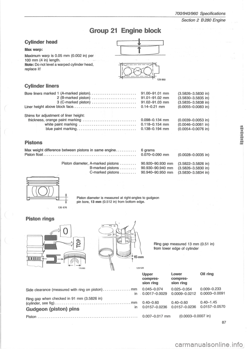
Max warp:
Maximum warp is 0.05 mm (0.002 in) per
100 mm (4 in) length.
I
[
Note: Do not level a warped cylinder head,
replace it!
n~Ql;J 129860
Cylinder liners
Bore liners marked 1 (A-marked piston) ........................ .
2 (B-marked piston) ....................... .
3 (C-marked piston) ....................... .
Liner height above
block face ................................. .
Shims for adjustment of liner height:
thickness, orange paint marking
............................ .
white paint marking
.............................. .
blue paint marking ............................... .
Pistons
Max weight difference between pistons in same engine .......... .
Piston
float ..................................... ............ .
Piston diameter, A-marked pistons
........ .
B-marked pistons .
....... .
C-marked pistons
........ .
91.00-91.01 mm
91.01-91.02 mm
91.02-91.03 mm
0.14-0.21 mm
0 .098-0.134 mm
0.118-0.154 mm
0.138-0.194 mm
6 grams
0.070-0.090 mm
90.920-90.930 mm
90.930-90.940 mm
90 .940-90.950 mm
(3.5826-3 .5830 in)
(3.5830-3.5835 in)
(3.5835-3.5838 in)
(0.0055-0.0083 in)
(0.0039-0.0053 in)
(0. 0046-0.0061 in)
(0.0054-0.0076 in)
(0.0028-0 .0035 in)
(3.5822-3.5826 in)
(3.5826-3.5830 in)
(3.5830-3.5834 in)
((0)) t
~ ~~ Piston diameter is measured at right-angles to gudgeon pin bore, 13 mm (0.512 in) from bottom edge.
135676
Piston rings
Side clearance (measured with ring on piston) .. ............ . mm
Ring gap measured 13 mm (0.51 in)
from
lower edge of cylinder
Upp er Lower Oil ring
com pres-compres-
sion ring sion ring
0.045-0.
074
0.025-0.054 0.009-0.233
in
Ring gap when checked in 91 mm (3.5826 in)
. 0.0017-0.0029
0.0009-0.0212 0.0003-0.0091
(cylinder,
see fig) ..................................... .... mm
Gudgeon (piston ) pins in
0.40-0.60 0.40-0.60 0.40-1.45
0.0157-0.0236 0.0157-0.0236 0.0157-0.0570
Piston. . . . . . . . . . . . . . . . . . . . . . . . . . . . . . . . . . . . . . . . . . . . . . . . . . . . . . 0.007-0.017 mm (0.0003-0.0007 in)
87
"' lit ill lit ·,11 tit ill, til Itil
Page 92 of 168
70019401960 Specifications
Section
2 B 280 Engine
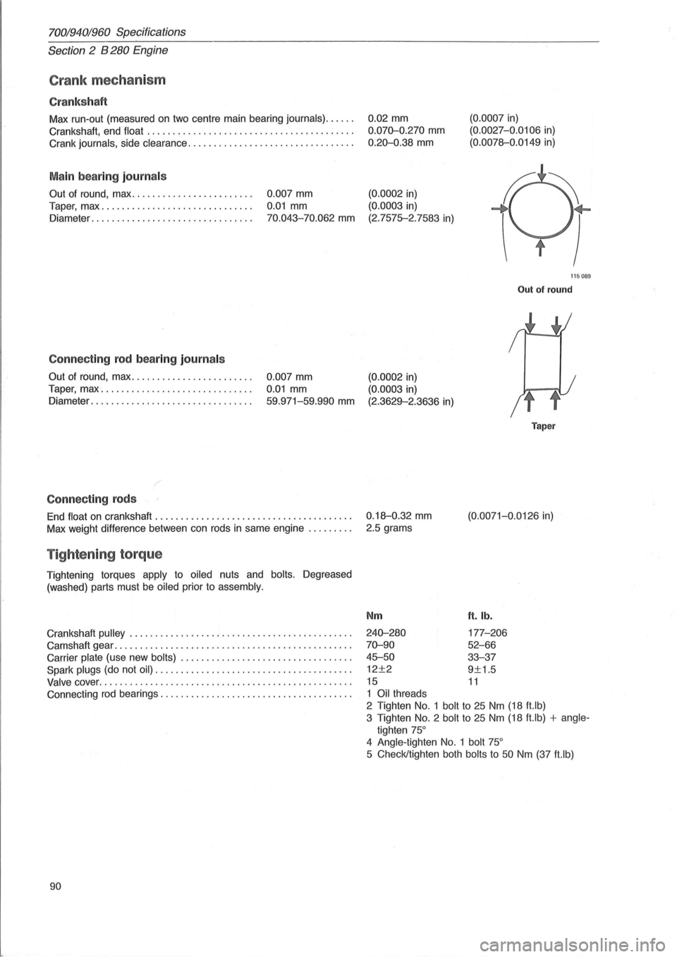
Crank mechanism
Cranks haft
Max run-out (measured on two centre main bearing journals) ..... .
Crankshaft, end
float ........................................ .
Crank
journals, side clearance ................................ .
Main bearing journal s
Out of round, max. ; ..................... .
Taper, max
............................. .
Diameter
............................... .
Connecting rod bearing journal s
Out of round, max ....................... .
Taper,
max " ............................. .
Diameter
............................ ... .
Connecting rods
0.007 mm
0.01 mm
70.043-70.062 mm
0.007 mm
0.01 mm
59.971-59.990 mm
End float on crankshaft ...................................... .
Max weight difference between can rods
in same engine ........ .
Tightening torque
Tightening torques apply to oiled nuts and bolts. Degreased
(washed) parts must
be oiled prior to assembly.
Crankshaft pulley ........................ ................... .
Camshaft gear
.............................................. .
Carrier
plate (use new bolts) ................................. .
Spark
plugs (do not oil) .. .................................... .
Valve cover ........................................... ...... .
Connecting
rod bearings ..................................... .
90 0.02
mm
0.070-0.270 mm
0.20-0.38 mm
(0.0002 in)
(0.0003
in)
(2.7575-2.7583
in)
(0.0007 in)
(0. 0027-0.0106 in)
(0.0078--0.0149
in)
115089
Out of round
(0.0002 in)
(0.0003 in)
(2.3629--2.3636 in)
0.18--0.32
mm
2.5 grams
Nm
240-280
70-90
45-50
12±2
15
1 Oil threads
Taper
(0.0071-0.0126 in)
ft. lb.
177-206
52-66
33-37
9±1.5
11
2 Tighten No.1 bolt to 25 Nm (18 ft.lb)
3 Tighten
No.2 bolt to 25 Nm (18 ft.lb) + angle
tighten 75°
4 Angle -tighten No. 1 bolt 75°
5 Check/tighten both bolts to 50 Nm (37 ft.lb)
Page 94 of 168
70019401960 Specifications
Section 2 B 280 Engine
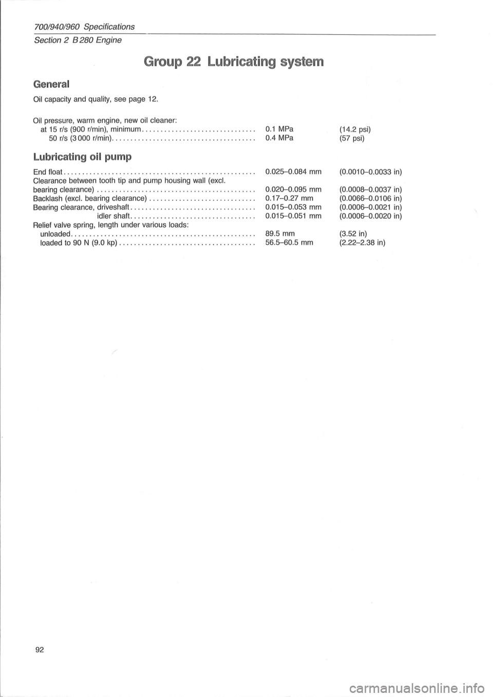
Group 22 Lubricating system
General
Oil capacity and quality, see page 12.
Oil pressure, warm engine , new oil cleaner:
at 15 rls (900 r/min), minimum. . . . . . . . . . . . . . . . . . . . . . . . . . . . . . . 0.1 MPa
50 rls (3000 r/min). . . . . . . . . . . . . . . . . . . . . . . . . . . . . . . . . . . . . . . 0.4 MPa
Lubricating oil pump
End float ...... ........................ ..................... .
Clearance between tooth tip and pump housing wall (excl.
bearing clearance) .
......................................... .
Backlash (excl. bearing clearance) ............................ .
Bearing clearance , driveshaft ....
............................. .
idler shaft ................................. .
Relief valve spring, length under various loads:
unloaded
..................... ................. ........... .
loaded to 90 N (9.0 kp) .................................... .
92
0.025-0.084 mm
0.020-0.095 mm
0.17 -0.27 mm
0.015-0.053 mm
0.015-0.051 mm
89.5 mm
56.5-60.5 mm
(14.2 psi)
(57 psi)
(0.0010-0 .0033 in)
(0.0008-0 .0037 in)
(0.0066-0 .0106 in)
(0.0006-0 .0021 in)
(0.0006-0.0020 in)
(3.52 in)
(2.22-2.38 in)
Page 101 of 168
(
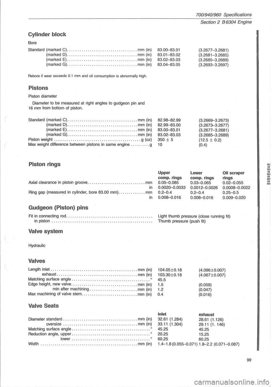
Cylinder block
Bore
Standard (marked C)
........................... ....... mm (in)
(marked
D) ........... ....................... mm (in)
(marked
E) .................................. mm (in)
(marked
G) ................... . .............. mm (in)
Rebore if wear exceeds 0.1 mm and oil consumption is abnormally high.
Pistons
Piston diameter
Diameter to be measured at right
angles to gudgeon pin and
16 mm from bottom of piston.
Standard (marked C)
.................................. mm (in)
(marked
D): ................................ . mm (in)
(marked
E) .. , ........................ ....... mm (in)
(marked
G) ............ ...................... mm (in)
Piston weight
.......................................... g (oz)
Max weight difference between pistons in same engine
......... g
Piston rings
Axial clearance in piston groove ............................ mm
in
Ring gap (measured in cylinder, bore 83.00 mm) ............. mm ? in
Gudgeon (P iston ) pins
Fit in connecting rod ......................................... .
in piston
................................................ .
Valve system
Hydraulic
Valves
Length inlet ...... .................................... mm (in)
exhaust
.............. ......................... mm (in)
Matching surface
angle .................................. .... 0
Edge height, new valve ................................ mm (in)
min after machining .
...................... mm (in)
Max machining of
valve stem ................ ........... mm (in)
Valve Seats
Diameter standard .................................... mm (in)
oversize
.... ................................ mm (in)
Matching surface
angle .......................... ............ 0
Reduction angle, upper ...................................... 0
lower ................. ....... .............. 0
Width ...................................... ... ...... mm (in)
70019401960 Specifications
Section 2 B 6304 Engine
83.00-83.01
83.01-83 .02
83.02-83.03
83.04-83.05
82.98--82.99
82.99--83.00
83.00-83.01
83.02 -83.03
350
± 5
10
(3.2677-3 .2681 )
(3.2681-3.2685)
(3.2685-3 .2689)
(3.2693-3.2697)
(3.2669--3.26 7
3)
(3.2673-3.2677)
(3.2677-3.
2681 )
(3.2685-3.2689)
(12.5 ±
0.2)
(0.4)
Upper
camp. rings
0.05-0.085
0.0020-0.0033
0.2-0.4
0.008--0.016
Lower
camp. rings
0.03-0.065
0.0012-0.0026
0.2-0.4
0.008--0.016
Oil scraper
ring s
0.02-0.055
0.0008 -0.0022
0.25-0.5
0.009--0 .020
Light thumb pressure (close running fit)
Thumb pressure (push fit)
104.05±0.18
103.30±0.18
45.5
1.5
1.2
0 .4 (4
.
096±0.007)
(4.067±0. 007)
(0.059)
(0.047)
(0.016)
inl et exhaust
32.61 (1.284) 28.61 (1.126)
33.11
(1.304) 29 .11 (1.146)
45.25 45.25
20.25 15.25
60.25 60.25
1.4-1.8 (0.055-0.071) 1.8--2.2 (0.071-0.087)
99
Itl
It
Itl
.... 1 '11 Itl ... Itl
Page 102 of 168
70019401960 Specifications
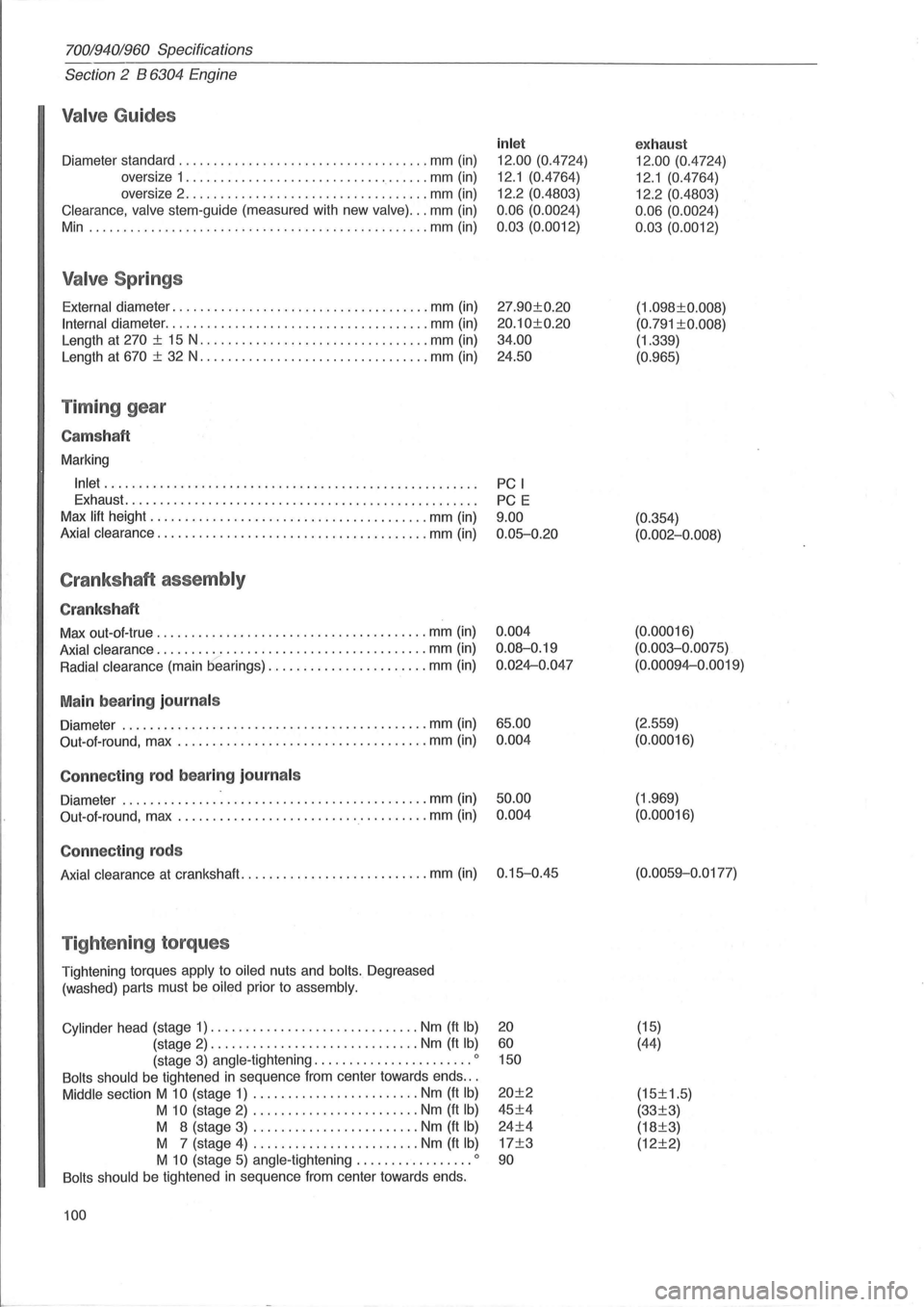
Section 2 B 6304 Engine
Valve Guides
Diameter standard .................................... mm (in)
oversize 1
................................... mm (in)
oversize 2
...................... ............. mm (in)
Clearance, valve stem-guide (measured with new valve) ... mm (in)
Min .
................................................ mm (in)
Valve Springs
External diameter ..................................... mm (in)
Internal diameter ...................................... mm (in)
Length at
270 ± 15 N ................................. mm (in)
Length at
670 ± 32 N ................................. mm (in)
Timing gear
Cams haft
Marking
Inlet ..................................................... .
Exhaust
.................................................. .
Max
lift height ................... ..................... mm (in)
Axial clearance ....................................... mm (in)
Crankshaft assembly
Crankshaft
Max out-ol-true ...................................... . mm (in)
Axial clearance ....................................... mm (in)
Radial clearance (main bearings) ....................... mm (in)
Main bearing journals
Diameter ............................................ mm (in)
Out-ol-round, max
.................................... mm (in)
Connecting rod bearing journ als
Diameter ................................... ......... mm (in)
Out-aI-round, max
.................................... mm (in)
Connecting rods
Axial clearance at crankshaft ........................... mm (in)
Tightening torques
Tightening torques apply to oiled nuts and bolts. Degreased
(washed) parts must
be oiled prior to assembly.
Cylinder
head (stage 1) .............................. Nm (ft Ib)
(stage 2) .............................. Nm (ft Ib)
(stage 3) angle -tightening ....................... 0
Bolts should be tightened in sequence Irom center towards ends .. .
Middle section M 10 (stage 1) ........................ Nm (ft Ib)
M 10 (stage 2) ........................ Nm (ft Ib)
M 8 (stage 3) ........................ Nm (It Ib)
M 7 (stage 4) ........................ Nm (It Ib)
M 10 (stage 5) angle -tightening ................. 0
Bolts should be tightened in sequence Irom center towards ends.
100
inlet
12.00 (0.4724)
12.1 (0.4764)
12.2 (0.4803)
0.06 (0.0024)
0.03 (0.0012)
27.90±0.20
20.10±0.20
34.00
24.50
PC I
PC E
9.00 0.05-0.20
0.004
0.08-0.19
0.024-0.047
65.00 0.004
50.00 0.004
0.15-0.45
20
60 150
20±2
45±4
24±4
17±3
90
exhaust
12.00 (0.4724)
12.1 (0.4764)
12.2 (0.4803)
0.06 (0.0024)
0.03 (0.0012)
(1.098±0.008)
(0.791 ±0.008)
(1.339)
(0.965)
(0.354)
(0.002-0.008)
(0. 00016)
(0.003-0.0075)
(0.00094-0.0019)
(2.559)
(0.00016)
(1.969)
(0.00016)
(0.0059-0 .0177)
(15)
(44)
(15±1.5)
(33±3)
(18±3)
(12±2)